Page 1807 of 2395

RHA273D
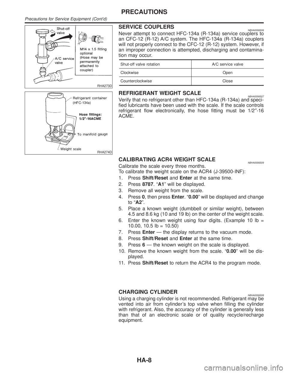
SERVICE COUPLERSNBHA0006S06Never attempt to connect HFC-134a (R-134a) service couplers to
an CFC-12 (R-12) A/C system. The HFC-134a (R-134a) couplers
will not properly connect to the CFC-12 (R-12) system. However, if
an improper connection is attempted, discharging and contamina-
tion may occur.
Shut-off valve rotation A/C service valve
Clockwise Open
Counterclockwise Close
RHA274D
REFRIGERANT WEIGHT SCALENBHA0006S07Verify that no refrigerant other than HFC-134a (R-134a) and speci-
fied lubricants have been used with the scale. If the scale controls
refrigerant flow electronically, the hose fitting must be 1/2²-16
ACME.
CALIBRATING ACR4 WEIGHT SCALENBHA0006S09Calibrate the scale every three months.
To calibrate the weight scale on the ACR4 (J-39500-INF):
1. PressShift/ResetandEnterat the same time.
2. Press8787.ªA1º will be displayed.
3. Remove all weight from the scale.
4. Press0, then pressEnter.ª0.00º will be displayed and change
to ªA2º.
5. Place a known weight (dumbbell or similar weight), between
4.5 and 8.6 kg (10 and 19 lb) on the center of the weight scale.
6. Enter the known weight using four digits. (Example 10 lb =
10.00, 10.5 lb = 10.50)
7. PressEnterÐ the display returns to the vacuum mode.
8. PressShift/ResetandEnterat the same time.
9. Press6Ð the known weight on the scale is displayed.
10. Remove the known weight from the scale. ª0.00º will be dis-
played.
11. PressShift/Resetto return the ACR4 to the program mode.
CHARGING CYLINDERNBHA0006S08Using a charging cylinder is not recommended. Refrigerant may be
vented into air from cylinder's top valve when filling the cylinder
with refrigerant. Also, the accuracy of the cylinder is generally less
than that of an electronic scale or of quality recycle/recharge
equipment.
PRECAUTIONS
Precautions for Service Equipment (Cont'd)
HA-8
Page 1808 of 2395
Wiring Diagrams and Trouble DiagnosesNBHA0007When you read wiring diagrams, refer to the following:
IGI-11, ªHOW TO READ WIRING DIAGRAMSº
IEL-10, ªWiring Diagram Ð POWER к for power distribution
circuit
When you perform trouble diagnoses, refer to the following:
IGI-34, ªHOW TO FOLLOW TROUBLE DIAGNOSESº
IGI-24, ªHOW TO PERFORM EFFICIENT DIAGNOSIS FOR
AN ELECTRICAL INCIDENTºGI
MA
EM
LC
EC
FE
AT
TF
PD
AX
SU
BR
ST
RS
BT
SC
EL
IDX
PRECAUTIONS
Wiring Diagrams and Trouble Diagnoses
HA-9
Page 1810 of 2395

HFC-134a (R-134a) Service Tools and
Equipment
=NBHA0009Never mix HFC-134a refrigerant and/or its specified lubricant with CFC-12 (R-12) refrigerant and/or its lubri-
cant.
Separate and non-interchangeable service equipment must be used for handling each type of refrigerant/
lubricant.
Refrigerant container fittings, service hose fittings and service equipment fittings (equipment which handles
refrigerant and/or lubricant) are different between CFC-12 (R-12) and HFC-134a (R-134a). This is to avoid
mixed use of the refrigerants/lubricant.
Adapters that convert one size fitting to another must never be used: refrigerant/lubricant contamination will
occur and compressor failure will result.
Tool number
(Kent-Moore No.)
Tool nameDescription
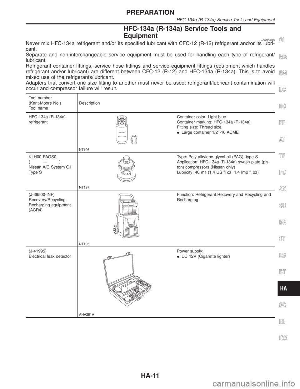
HFC-134a (R-134a)
refrigerant
NT196
Container color: Light blue
Container marking: HFC-134a (R-134a)
Fitting size: Thread size
ILarge container 1/2²-16 ACME
KLH00-PAGS0
(Ð)
Nissan A/C System Oil
Type S
NT197
Type: Poly alkylene glycol oil (PAG), type S
Application: HFC-134a (R-134a) swash plate (pis-
ton) compressors (Nissan only)
Lubricity: 40 m(1.4 US fl oz, 1.4 Imp fl oz)
(J-39500-INF)
Recovery/Recycling
Recharging equipment
(ACR4)
NT195
Function: Refrigerant Recovery and Recycling and
Recharging
(J-41995)
Electrical leak detector
AHA281A
Power supply:
IDC 12V (Cigarette lighter)
GI
MA
EM
LC
EC
FE
AT
TF
PD
AX
SU
BR
ST
RS
BT
SC
EL
IDX
PREPARATION
HFC-134a (R-134a) Service Tools and Equipment
HA-11
Page 1819 of 2395

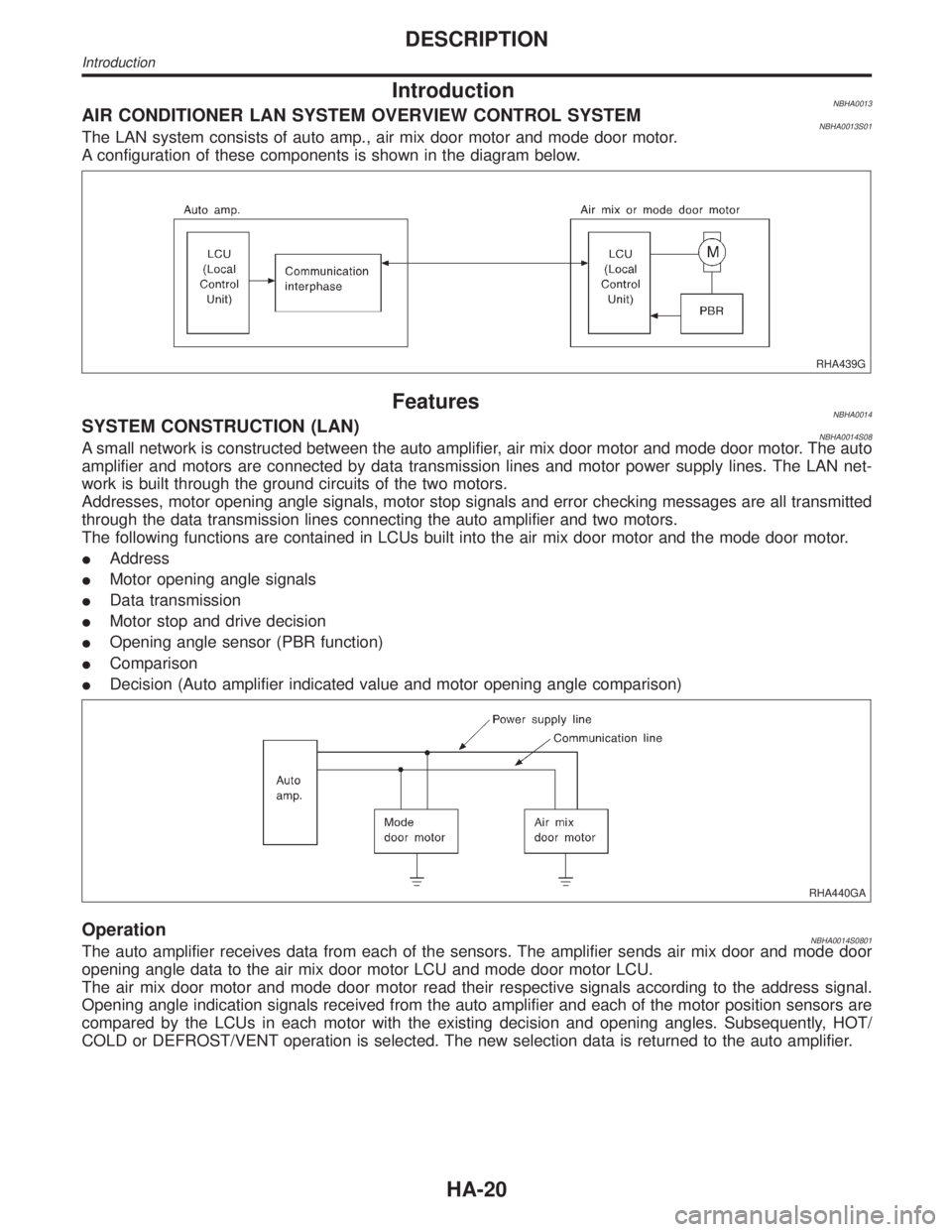
IntroductionNBHA0013AIR CONDITIONER LAN SYSTEM OVERVIEW CONTROL SYSTEMNBHA0013S01The LAN system consists of auto amp., air mix door motor and mode door motor.
A configuration of these components is shown in the diagram below.
RHA439G
FeaturesNBHA0014SYSTEM CONSTRUCTION (LAN)NBHA0014S08A small network is constructed between the auto amplifier, air mix door motor and mode door motor. The auto
amplifier and motors are connected by data transmission lines and motor power supply lines. The LAN net-
work is built through the ground circuits of the two motors.
Addresses, motor opening angle signals, motor stop signals and error checking messages are all transmitted
through the data transmission lines connecting the auto amplifier and two motors.
The following functions are contained in LCUs built into the air mix door motor and the mode door motor.
IAddress
IMotor opening angle signals
IData transmission
IMotor stop and drive decision
IOpening angle sensor (PBR function)
IComparison
IDecision (Auto amplifier indicated value and motor opening angle comparison)
RHA440GA
OperationNBHA0014S0801The auto amplifier receives data from each of the sensors. The amplifier sends air mix door and mode door
opening angle data to the air mix door motor LCU and mode door motor LCU.
The air mix door motor and mode door motor read their respective signals according to the address signal.
Opening angle indication signals received from the auto amplifier and each of the motor position sensors are
compared by the LCUs in each motor with the existing decision and opening angles. Subsequently, HOT/
COLD or DEFROST/VENT operation is selected. The new selection data is returned to the auto amplifier.
DESCRIPTION
Introduction
HA-20
Page 1820 of 2395

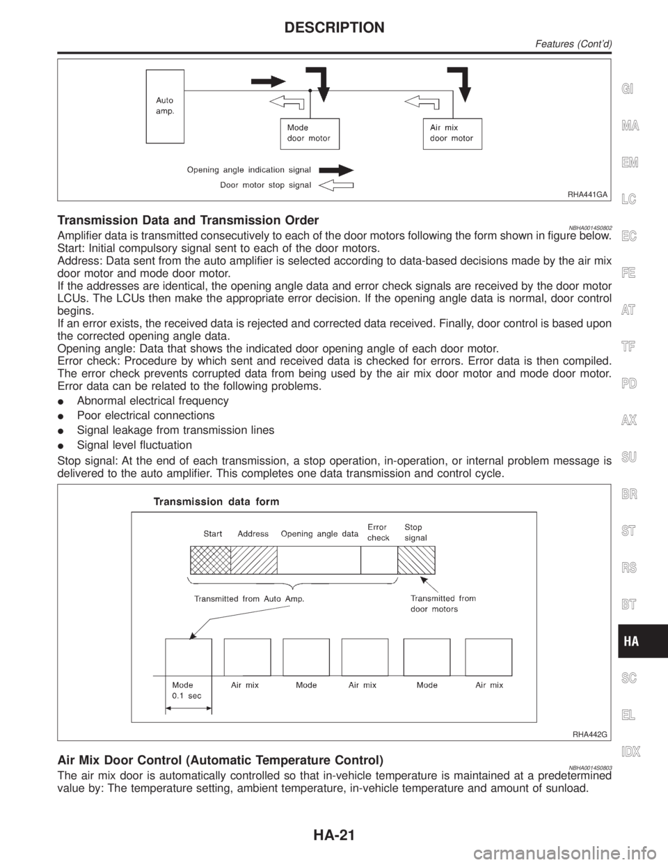
RHA441GA
Transmission Data and Transmission OrderNBHA0014S0802Amplifier data is transmitted consecutively to each of the door motors following the form shown in figure below.
Start: Initial compulsory signal sent to each of the door motors.
Address: Data sent from the auto amplifier is selected according to data-based decisions made by the air mix
door motor and mode door motor.
If the addresses are identical, the opening angle data and error check signals are received by the door motor
LCUs. The LCUs then make the appropriate error decision. If the opening angle data is normal, door control
begins.
If an error exists, the received data is rejected and corrected data received. Finally, door control is based upon
the corrected opening angle data.
Opening angle: Data that shows the indicated door opening angle of each door motor.
Error check: Procedure by which sent and received data is checked for errors. Error data is then compiled.
The error check prevents corrupted data from being used by the air mix door motor and mode door motor.
Error data can be related to the following problems.
IAbnormal electrical frequency
IPoor electrical connections
ISignal leakage from transmission lines
ISignal level fluctuation
Stop signal: At the end of each transmission, a stop operation, in-operation, or internal problem message is
delivered to the auto amplifier. This completes one data transmission and control cycle.
RHA442G
Air Mix Door Control (Automatic Temperature Control)NBHA0014S0803The air mix door is automatically controlled so that in-vehicle temperature is maintained at a predetermined
value by: The temperature setting, ambient temperature, in-vehicle temperature and amount of sunload.
GI
MA
EM
LC
EC
FE
AT
TF
PD
AX
SU
BR
ST
RS
BT
SC
EL
IDX
DESCRIPTION
Features (Cont'd)
HA-21
Page 1823 of 2395

RHA328HA
DISPLAY SCREENNBHA0016S01Displays the operational status of the system.
AUTO SWITCHNBHA0016S02The compressor, intake doors, air mix door, outlet doors, and blower speed are automatically controlled so
that the in-vehicle temperature will reach, and be maintained at the set temperature selected by the operator.
ECON SWITCHNBHA0016S03By pressing the ECON switch, the display should indicate ECON and the compressor always turns OFF. With
the compressor OFF, the system will not remove heat (cool) or de-humidify. The system will maintain the in-
vehicle temperature at the set temperature when the set temperature is above the ambient (outside) tempera-
ture. The system will set the intake doors to the outside air position.
TEMPERATURE SWITCH (POTENTIO TEMPERATURE CONTROL) WITHOUT NAVIGATION
SYSTEM
NBHA0016S04Increases or decreases the set temperature.
OFF SWITCHNBHA0016S05The compressor and blower are OFF, the intake doors are set to the outside air position, and the air outlet
doors are set to the foot (80% foot and 20% defrost) position.
FAN SWITCHNBHA0016S06Manually controls the blower speed. Four speeds are available for manual control (as shown on the display
screen):
low
, medium low, medium high, high
RECIRCULATION (REC) SWITCHNBHA0016S07OFF position: Outside air is drawn into the passenger compartment.
ON position: Interior air is recirculated inside the vehicle.
DEFROSTER (DEF) SWITCHNBHA0016S08Positions the air outlet doors to the defrost position. Also positions the intake doors to the outside air position.
MODE SWITCHNBHA0016S09Controls the air discharge outlets.
TEMPERATURE DIAL (POTENTIO TEMPERATURE CONTROL) WITH NAVIGATION SYSTEMNBHA0016S10Increases or decreases the set temperature.
AMB (AMBIENT) SWITCH (WITH NAVIGATION SYSTEM)NBHA0016S11Shows the ambient (outside) air temperature on the display screen for 5 seconds.
DESCRIPTION
Control Operation (Cont'd)
HA-24
Page 1866 of 2395
RHA865H
RHA330HA
3. Check Discharge AirNBHA0019S02031. Press MODE switch four times and D/F button.
2. Each position indicator should change shape.
RHA654F
3. Confirm that discharge air comes out according to the air dis-
tribution table at left.
Refer to ªDischarge Air Flowº (HA-25).
NOTE:
Confirm that the compressor clutch is engaged (visual inspection)
and intake door position is at FRESH when the DEF
is
selected.
Intake door position is checked in the next step.
If NG, go to trouble diagnosis procedure for mode door motor
(HA-75).
If OK, continue with next check.
GI
MA
EM
LC
EC
FE
AT
TF
PD
AX
SU
BR
ST
RS
BT
SC
EL
IDX
TROUBLE DIAGNOSES
Operational Check (Cont'd)
HA-67
Page 1876 of 2395
SYSTEM DESCRIPTION=NBHA0052Component PartsNBHA0052S01Mode door control system components are:
1) Auto amp.
2) Mode door motor (LCU)
3) In-vehicle sensor
4) Ambient sensor
5) Sunload sensor
6) Intake sensor
System OperationNBHA0052S02The auto amplifier receives data from each of the sensors. The amplifier sends air mix door and mode door
opening angle data to the air mix door motor LCU and mode door motor LCU.
The air mix door motor and mode door motor read their respective signals according to the address signal.
Opening angle indication signals received from the auto amplifier and each of the motor position sensors are
compared by the LCUs in each motor with the existing decision and opening angles. Subsequently, HOT/
COLD or DEFROST/VENT operation is selected. The new selection data is returned to the auto amplifier.
RHA870H
GI
MA
EM
LC
EC
FE
AT
TF
PD
AX
SU
BR
ST
RS
BT
SC
EL
IDX
TROUBLE DIAGNOSES
Mode Door Motor (Cont'd)
HA-77