Page 2052 of 2395

SPD209A
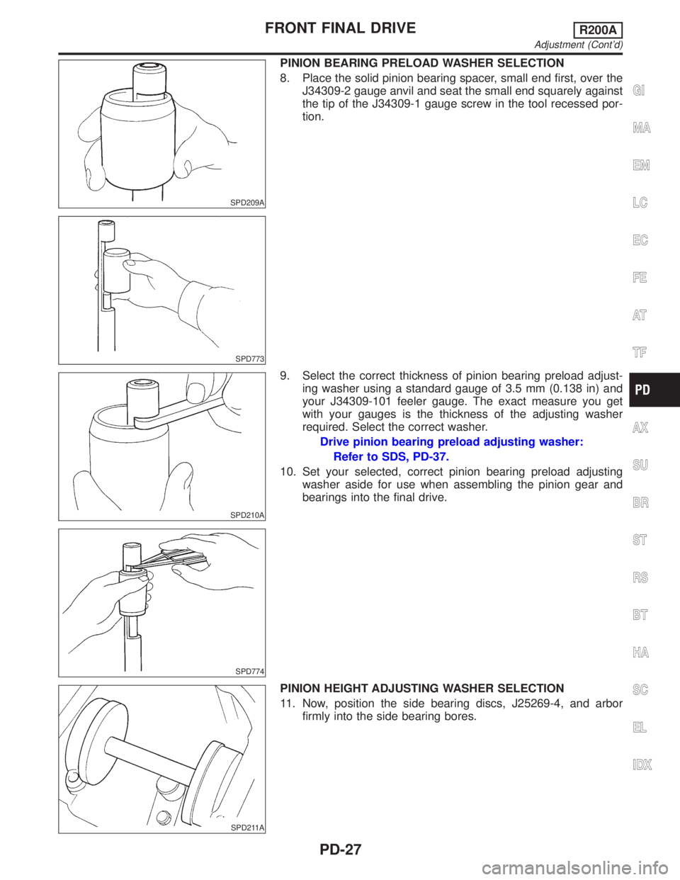
PINION BEARING PRELOAD WASHER SELECTION
8. Place the solid pinion bearing spacer, small end first, over the
J34309-2 gauge anvil and seat the small end squarely against
the tip of the J34309-1 gauge screw in the tool recessed por-
tion.
SPD773
SPD210A
SPD774
9. Select the correct thickness of pinion bearing preload adjust-
ing washer using a standard gauge of 3.5 mm (0.138 in) and
your J34309-101 feeler gauge. The exact measure you get
with your gauges is the thickness of the adjusting washer
required. Select the correct washer.
Drive pinion bearing preload adjusting washer:
Refer to SDS, PD-37.
10. Set your selected, correct pinion bearing preload adjusting
washer aside for use when assembling the pinion gear and
bearings into the final drive.
SPD211A
PINION HEIGHT ADJUSTING WASHER SELECTION
11. Now, position the side bearing discs, J25269-4, and arbor
firmly into the side bearing bores.
GI
MA
EM
LC
EC
FE
AT
TF
AX
SU
BR
ST
RS
BT
HA
SC
EL
IDX
FRONT FINAL DRIVER200A
Adjustment (Cont'd)
PD-27
Page 2053 of 2395
SPD212A
12. Install the side bearing caps and tighten the cap bolts.
Specification:
88 - 98 N´m (9 - 10 kg-m, 65 - 72 ft-lb)
SPD204A
13. Select the correct standard pinion height adjusting washer
thickness by using a standard gauge of 3.0 mm (0.118 in) and
your J34309-101 feeler gauge. Measure the gap between the
J34309-11 ªR200Aº pinion height adapter and the arbor.
SPD775
14. Write down your exact total measurement.
SPD542
15. Correct the pinion height washer size by referring to the ªpin-
ion head numberº.
There are two numbers painted on the pinion gear. The first
one refers to the pinion and ring gear as a matched set and
should be the same as the number on the ring gear. The sec-
ond number is the ªpinion head height numberº, and it refers
to the ideal pinion height from standard for quietest operation.
Use the following chart to determine the correct pinion height
washer. Refer to SDS, PD-37.
FRONT FINAL DRIVER200A
Adjustment (Cont'd)
PD-28
Page 2054 of 2395

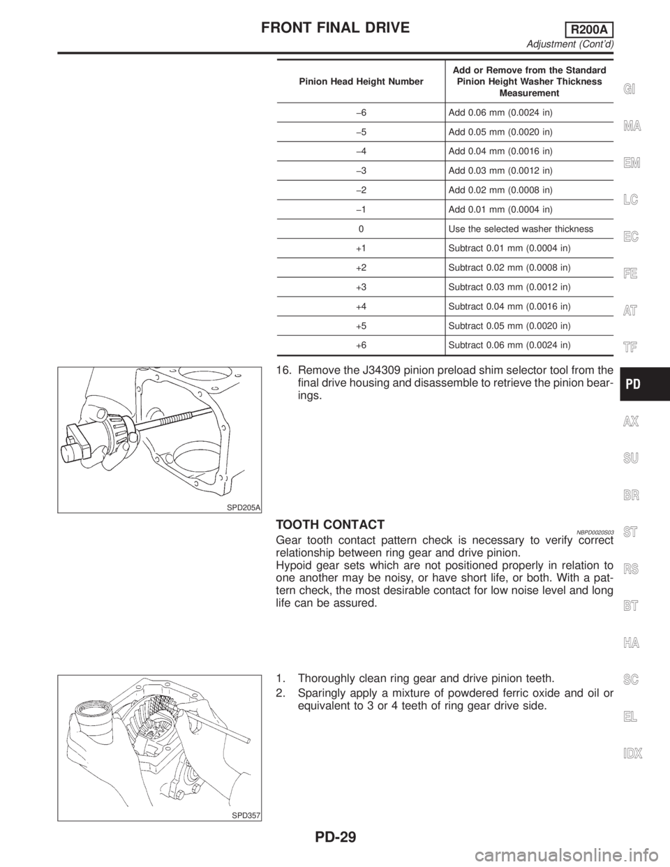
Pinion Head Height NumberAdd or Remove from the Standard
Pinion Height Washer Thickness
Measurement
þ6 Add 0.06 mm (0.0024 in)
þ5 Add 0.05 mm (0.0020 in)
þ4 Add 0.04 mm (0.0016 in)
þ3 Add 0.03 mm (0.0012 in)
þ2 Add 0.02 mm (0.0008 in)
þ1 Add 0.01 mm (0.0004 in)
0 Use the selected washer thickness
+1 Subtract 0.01 mm (0.0004 in)
+2 Subtract 0.02 mm (0.0008 in)
+3 Subtract 0.03 mm (0.0012 in)
+4 Subtract 0.04 mm (0.0016 in)
+5 Subtract 0.05 mm (0.0020 in)
+6 Subtract 0.06 mm (0.0024 in)
SPD205A
16. Remove the J34309 pinion preload shim selector tool from the
final drive housing and disassemble to retrieve the pinion bear-
ings.
TOOTH CONTACTNBPD0020S03Gear tooth contact pattern check is necessary to verify correct
relationship between ring gear and drive pinion.
Hypoid gear sets which are not positioned properly in relation to
one another may be noisy, or have short life, or both. With a pat-
tern check, the most desirable contact for low noise level and long
life can be assured.
SPD357
1. Thoroughly clean ring gear and drive pinion teeth.
2. Sparingly apply a mixture of powdered ferric oxide and oil or
equivalent to 3 or 4 teeth of ring gear drive side.
GI
MA
EM
LC
EC
FE
AT
TF
AX
SU
BR
ST
RS
BT
HA
SC
EL
IDX
FRONT FINAL DRIVER200A
Adjustment (Cont'd)
PD-29
Page 2056 of 2395
SPD655
2. Install extension tube retainer, rear axle bearing and rear axle
shaft bearing collar on differential side shaft.
SPD552
DIFFERENTIAL CASENBPD0021S021. Install side gears, pinion mate gears and thrust washers into
differential case.
SPD258
2. Fit pinion mate shaft to differential case so that it meets lock
pin holes.
3. Adjust backlash between side gear and pinion mate gear by
selecting side gear thrust washer.
Refer to SDS, PD-36.
Backlash between side gear and pinion mate gear
(Clearance between side gear thrust washer and differ-
ential case):
Less than 0.15 mm (0.0059 in)
SPD030
4. Install pinion mate shaft lock pin with a punch.
Make sure lock pin is flush with case.
SPD322
5. Apply gear oil to gear tooth surfaces and thrust surfaces and
check to see they turn properly.
GI
MA
EM
LC
EC
FE
AT
TF
AX
SU
BR
ST
RS
BT
HA
SC
EL
IDX
FRONT FINAL DRIVER200A
Assembly (Cont'd)
PD-31
Page 2057 of 2395
SPD554
6. Install differential case assembly on ring gear.
7. Apply locking agent [Locktite (stud lock) or equivalent] to ring
gear bolts, and install them.
Tighten bolts in a criss-cross pattern, lightly tapping bolt head
with a hammer.
PD353
8. Press-fit side bearing inner cones on differential case with Tool.
Tool number:
A KV38100300 (J25523)
B ST33061000 (J8107-2)
SPD679
FINAL DRIVE HOUSINGNBPD0021S031. Press-fit front and rear bearing outer races with Tools.
Tool number:
A ST30611000 (J25742-1)
B ST30621000 (J25742-5)
C ST30613000 (J25742-3)
SPD377
2. Select drive pinion height adjusting washer and pinion bearing
adjusting washer. Refer to ªPINION GEAR HEIGHT AND PIN-
ION BEARING PRELOADº, PD-25.
3. Install drive pinion height adjusting washer in drive pinion, and
press-fit pinion rear bearing inner cone in it, using press and
Tool.
Tool number:
ST30901000 (J26010-01)
FRONT FINAL DRIVER200A
Assembly (Cont'd)
PD-32
Page 2059 of 2395
SPD664
9. Turn drive pinion in both directions several revolutions, and
measure pinion bearing preload.
Tool number: ST3127S000 (J25765-A)
Pinion bearing preload:
1.1 - 1.4 N´m (11 - 14 kg-cm, 9.5 - 12.2 in-lb)
When pinion bearing preload is outside the specifications,
replace pinion bearing adjusting washer and spacer with a
different thickness.
SPD527
10. Select side bearing adjusting washer.
Refer to ªSIDE BEARING PRELOADº, PD-24.
11. Install differential case assembly with side bearing outer races
into final drive housing.
SPD558
12. Insert left and right side bearing adjusting washers in place
between side bearings and final drive housing.
SPD559
13. Drive in side bearing spacer with Tool.
Tool number: KV38100600 (J25267)
SPD526
14. Align mark on bearing cap with that on final drive housing and
install bearing cap on final drive housing.
FRONT FINAL DRIVER200A
Assembly (Cont'd)
PD-34
Page 2064 of 2395

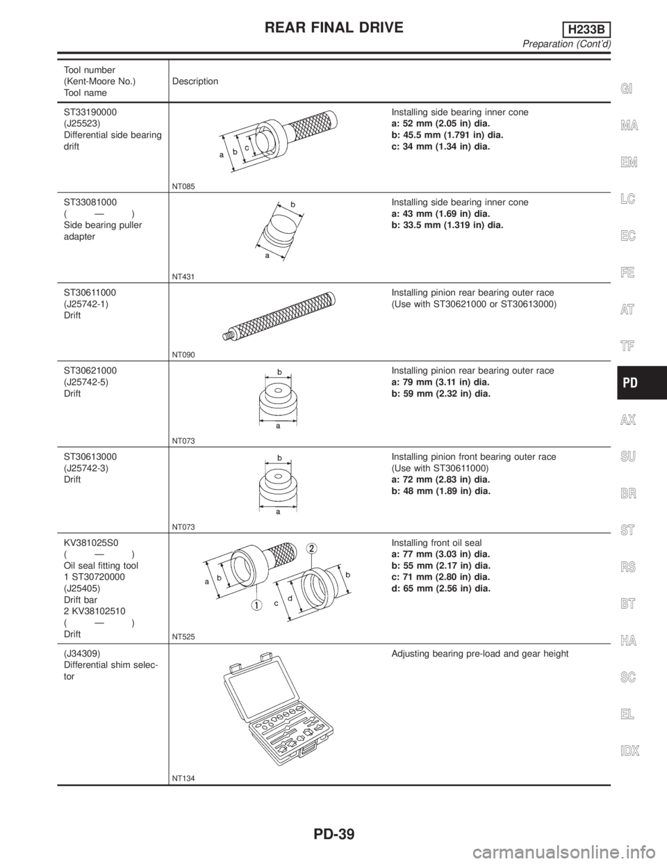
Tool number
(Kent-Moore No.)
Tool nameDescription
ST33190000
(J25523)
Differential side bearing
drift
NT085
Installing side bearing inner cone
a: 52 mm (2.05 in) dia.
b: 45.5 mm (1.791 in) dia.
c: 34 mm (1.34 in) dia.
ST33081000
(Ð)
Side bearing puller
adapter
NT431
Installing side bearing inner cone
a: 43 mm (1.69 in) dia.
b: 33.5 mm (1.319 in) dia.
ST30611000
(J25742-1)
Drift
NT090
Installing pinion rear bearing outer race
(Use with ST30621000 or ST30613000)
ST30621000
(J25742-5)
Drift
NT073
Installing pinion rear bearing outer race
a: 79 mm (3.11 in) dia.
b: 59 mm (2.32 in) dia.
ST30613000
(J25742-3)
Drift
NT073
Installing pinion front bearing outer race
(Use with ST30611000)
a: 72 mm (2.83 in) dia.
b: 48 mm (1.89 in) dia.
KV381025S0
(Ð)
Oil seal fitting tool
1 ST30720000
(J25405)
Drift bar
2 KV38102510
(Ð)
Drift
NT525
Installing front oil seal
a: 77 mm (3.03 in) dia.
b: 55 mm (2.17 in) dia.
c: 71 mm (2.80 in) dia.
d: 65 mm (2.56 in) dia.
(J34309)
Differential shim selec-
tor
NT134
Adjusting bearing pre-load and gear height
GI
MA
EM
LC
EC
FE
AT
TF
AX
SU
BR
ST
RS
BT
HA
SC
EL
IDX
REAR FINAL DRIVEH233B
Preparation (Cont'd)
PD-39
Page 2065 of 2395
Tool number
(Kent-Moore No.)
Tool nameDescription
(J25269-18)
Side bearing discs
(2 Req'd)
NT135
Selecting pinion height adjusting washer
KV381052S0
(Ð)
Rear axle shaft dummy
1 KV38105210
(Ð)
Torque wrench side
2 KV38105220
(Ð)
Vice side
NT142
Checking differential torque on limited slip differen-
tial
KV38100500
(J25273)
Gear carrier front oil
seal drift
NT115
Installing front oil seal
a: 85 mm (3.35 in) dia.
b: 60 mm (2.36 in) dia.
Noise, Vibration and Harshness (NVH)
Troubleshooting
NBPD0051Refer to ªNVH TROUBLESHOOTING CHARTº, PD-3.
SPD479A
On-vehicle Service
FRONT OIL SEAL REPLACEMENTNBPD00301. Remove propeller shaft.
2. Loosen drive pinion nut.
Tool number: KV38108300 (J44195)
SPD737
3. Remove companion flange.
REAR FINAL DRIVEH233B
Preparation (Cont'd)
PD-40