2001 INFINITI QX4 steering wheel
[x] Cancel search: steering wheelPage 1999 of 2395

NBMA0003
General maintenance includes those items which should be checked during the normal day-to-day operation
of the vehicle. They are essential if the vehicle is to continue operating properly. The owners can perform
checks and inspections themselves or they can have their INFINITI dealers do them.
OUTSIDE THE VEHICLE
The maintenance items listed here should be performed from time to time, unless otherwise specified.
ItemReference page
TiresCheck the pressure with a gauge periodically when at a service station,
including the spare, and adjust to the specified pressure if necessary. Check
carefully for damage, cuts or excessive wear.Ð
Wheel nutsWhen checking the tires, make sure no nuts are missing, and check for any
loose nuts. Tighten if necessary.Ð
Tire rotationTires should be rotated every 12,000 km (7,500 miles). MA-24
Wheel alignment and
balanceIf the vehicle pulls to either side while driving on a straight and level road, or
if you detect uneven or abnormal tire wear, there may be a need for wheel
alignment. If the steering wheel or seat vibrates at normal highway speeds,
wheel balancing may be needed.MA-24, SU-6, ªFront
Wheel Alignmentº
Windshield wiper
bladesCheck for cracks or wear if they do not wipe properly. Ð
Doors and engine
hoodCheck that all doors and the engine hood operate smoothly as well as the
trunk lid and back hatch. Also make sure that all latches lock securely. Lubri-
cate if necessary. Make sure that the secondary latch keeps the hood from
opening when the primary latch is released.
When driving in areas using road salt or other corrosive materials, check
lubrication frequently.MA-27
INSIDE THE VEHICLE
The maintenance items listed here should be checked on a regular basis, such as when performing periodic maintenance, cleaning the
vehicle, etc.
ItemReference page
LampsMake sure that the headlamps, stop lamps, tail lamps, turn signal lamps, and
other lamps are all operating properly and installed securely. Also check
headlamp aim.Ð
Warning lamps and
buzzers/chimesMake sure that all warning lamps and buzzers/chimes are operating properly. Ð
Windshield wiper
and washerCheck that the wipers and washer operate properly and that the wipers do
not streak.Ð
Windshield defrosterCheck that the air comes out of the defroster outlets properly and in sufficient
quantity when operating the heater or air conditioning.Ð
Steering wheelCheck that it has the specified play. Be sure to check for changes in the
steering condition, such as excessive play, hard steering or strange noises.
Free play: Less than 35 mm (1.38 in)Ð
SeatsCheck seat position controls such as seat adjusters, seatback recliner, etc. to
make sure they operate smoothly and that all latches lock securely in every
position. Check that the head restrains move up and down smoothly and that
the locks (if equipped) hold securely in all latched positions. Check that the
latches lock securely for folding-down rear seatbacks.Ð
Seat beltsCheck that all parts of the seat belt system (e.g. buckles, anchors, adjusters
and retractors) operate properly and smoothly and are installed securely.
Check the belt webbing for cuts, fraying, wear or damage.MA-28, RS-7, ªSeat Belt
Inspectionº
BrakesCheck that the brake does not pull the vehicle to one side when applied. Ð
GENERAL MAINTENANCE
MA-4
Page 2001 of 2395
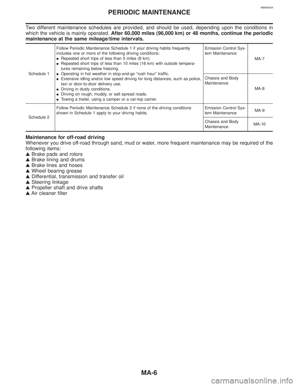
NBMA0004
Two different maintenance schedules are provided, and should be used, depending upon the conditions in
which the vehicle is mainly operated.After 60,000 miles (96,000 km) or 48 months, continue the periodic
maintenance at the same mileage/time intervals.
Schedule 1Follow Periodic Maintenance Schedule 1 if your driving habits frequently
includes one or more of the following driving conditions:
IRepeated short trips of less than 5 miles (8 km).
IRepeated short trips of less than 10 miles (16 km) with outside tempera-
tures remaining below freezing.
IOperating in hot weather in stop-and-go ªrush hourº traffic.
IExtensive idling and/or low speed driving for long distances, such as police,
taxi or door-to-door delivery use.
IDriving in dusty conditions.
IDriving on rough, muddy, or salt spread roads.
ITowing a trailer, using a camper or a car-top carrier.Emission Control Sys-
tem Maintenance
MA-7
Chassis and Body
Maintenance
MA-8
Schedule 2Follow Periodic Maintenance Schedule 2 if none of the driving conditions
shown in Schedule 1 apply to your driving habits.Emission Control Sys-
tem MaintenanceMA-9
Chassis and Body
MaintenanceMA-10
Maintenance for off-road driving
Whenever you drive off-road through sand, mud or water, more frequent maintenance may be required of the
following items:
GBrake pads and rotors
GBrake lining and drums
GBrake lines and hoses
GWheel bearing grease
GDifferential, transmission and transfer oil
GSteering linkage
GPropeller shaft and drive shafts
GAir cleaner filter
PERIODIC MAINTENANCE
MA-6
Page 2003 of 2395
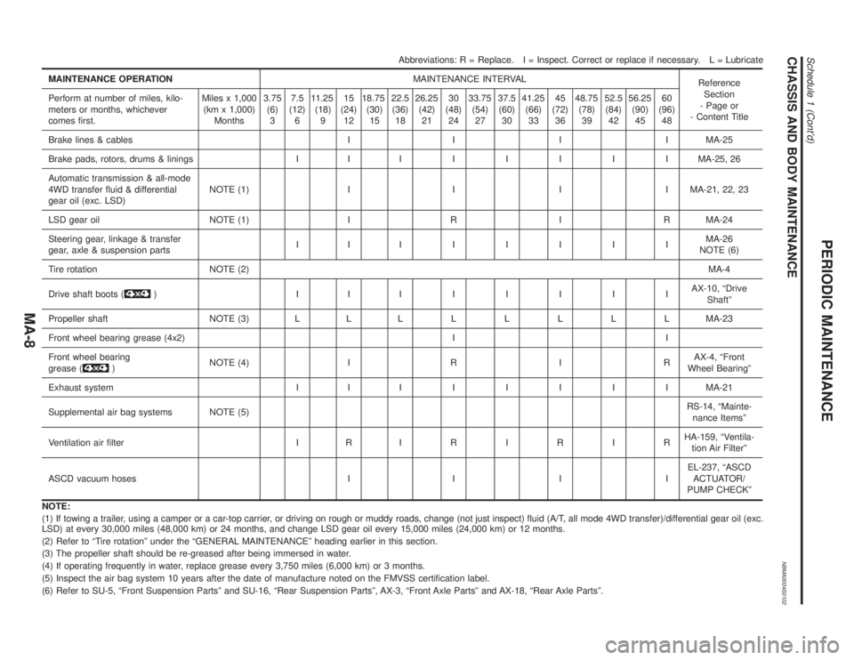
CHASSIS AND BODY MAINTENANCENBMA0004S0102
Abbreviations: R = Replace. I = Inspect. Correct or replace if necessary. L = Lubricate
MAINTENANCE OPERATIONMAINTENANCE INTERVAL
Reference
Section
- Page or
- Content Title Perform at number of miles, kilo-
meters or months, whichever
comes first.Miles x 1,000
(km x 1,000)
Months3.75
(6)
37.5
(12)
611.25
(18)
915
(24)
1218.75
(30)
1522.5
(36)
1826.25
(42)
2130
(48)
2433.75
(54)
2737.5
(60)
3041.25
(66)
3345
(72)
3648.75
(78)
3952.5
(84)
4256.25
(90)
4560
(96)
48
Brake lines & cables I I I I MA-25
Brake pads, rotors, drums & linings I IIIIIIIMA-25, 26
Automatic transmission & all-mode
4WD transfer fluid & differential
gear oil (exc. LSD)NOTE (1) I I I I MA-21, 22, 23
LSD gear oil NOTE (1) I R I R MA-24
Steering gear, linkage & transfer
gear, axle & suspension partsIIIIIIIIMA-26
NOTE (6)
Tire rotation NOTE (2)MA-4
Drive shaft boots (
) IIIIIIIIAX-10, ªDrive
Shaftº
Propeller shaft NOTE (3) L LLLLLLLMA-23
Front wheel bearing grease (4x2) I I
Front wheel bearing
grease (
)NOTE (4) I R I RAX-4, ªFront
Wheel Bearingº
Exhaust system I IIIIIIIMA-21
Supplemental air bag systems NOTE (5)RS-14, ªMainte-
nance Itemsº
Ventilation air filter I RIRIRIRHA-159, ªVentila-
tion Air Filterº
ASCD vacuum hoses I I I IEL-237, ªASCD
ACTUATOR/
PUMP CHECKº
NOTE:
(1) If towing a trailer, using a camper or a car-top carrier, or driving on rough or muddy roads, change (not just inspect) fluid (A/T, all mode 4WD transfer)/differential gear oil (exc.
LSD) at every 30,000 miles (48,000 km) or 24 months, and change LSD gear oil every 15,000 miles (24,000 km) or 12 months.
(2) Refer to ªTire rotationº under the ªGENERAL MAINTENANCEº heading earlier in this section.
(3) The propeller shaft should be re-greased after being immersed in water.
(4) If operating frequently in water, replace grease every 3,750 miles (6,000 km) or 3 months.
(5) Inspect the air bag system 10 years after the date of manufacture noted on the FMVSS certification label.
(6) Refer to SU-5, ªFront Suspension Partsº and SU-16, ªRear Suspension Partsº, AX-3, ªFront Axle Partsº and AX-18, ªRear Axle Partsº.
PERIODIC MAINTENANCE
Schedule 1 (Cont'd)
MA-8
Page 2005 of 2395
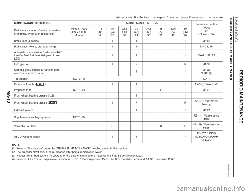
CHASSIS AND BODY MAINTENANCENBMA0004S0202
Abbreviations: R = Replace. I = Inspect. Correct or replace if necessary. L = Lubricate
MAINTENANCE OPERATIONMAINTENANCE INTERVAL
Reference Section
- Page
or
- Content Title Perform at number of miles, kilometers
or months, whichever comes first.Miles x 1,000
(km x 1,000)
Months7.5
(12)
615
(24)
1222.5
(36)
1830
(48)
2437.5
(60)
3045
(72)
3652.5
(84)
4260
(96)
48
Brake lines & cablesIIIIMA-25
Brake pads, rotors, drums & liningsIIIIMA-25, 26
Automatic transmission & all-mode 4WD
transfer fluid & differential gear oil (exc.
LSD)IIIIMA-21, 22, 23
LSD gear oilIRIRMA-24
Steering gear, linkage & transfer gear,
axle & suspension partsIIMA-26
NOTE (4)
Tire rotation NOTE (1)MA-4
Drive shaft boots (
) IIIIAX-10, ªDrive shaftº
Propeller shaft NOTE (2)LLLLMA-23
Front wheel bearing grease (4x2) I I
Front wheel bearing grease (
) IRIRAX-4, ªFront Wheel
Bearingº
Exhaust systemI I MA-21
Supplemental air bag systems NOTE (3)RS-14, ªMaintenance
Itemº
Ventilation air filterRRRRHA-159, ªVentilation Air
Filterº
ASCD vacuum hosesIIIIEL-237, ªASCD
ACTUATOR/PUMP
CHECKº
NOTE:
(1) Refer to ªTire rotationº under the ªGENERAL MAINTENANCEº heading earlier in this section.
(2) The propeller shaft should be re-greased after being immersed in water.
(3) Inspect the air bag system 10 years after the date of manufacture noted on the FMVSS certification label.
(4) Refer to SU-5, ªFront Suspension Partsº and SU-16, ªRear Suspension Partsº, AX-3, ªFront Axle Partsº and AX-18, ªRear Axle Partsº.
PERIODIC MAINTENANCE
Schedule 2 (Cont'd)
MA-10
Page 2021 of 2395
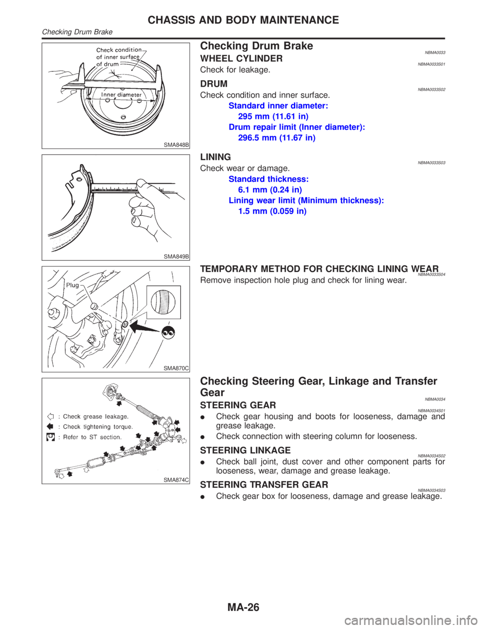
SMA848B
Checking Drum BrakeNBMA0033WHEEL CYLINDERNBMA0033S01Check for leakage.
DRUMNBMA0033S02Check condition and inner surface.
Standard inner diameter:
295 mm (11.61 in)
Drum repair limit (Inner diameter):
296.5 mm (11.67 in)
SMA849B
LININGNBMA0033S03Check wear or damage.
Standard thickness:
6.1 mm (0.24 in)
Lining wear limit (Minimum thickness):
1.5 mm (0.059 in)
SMA870C
TEMPORARY METHOD FOR CHECKING LINING WEARNBMA0033S04Remove inspection hole plug and check for lining wear.
SMA874C
Checking Steering Gear, Linkage and Transfer
Gear
NBMA0034STEERING GEARNBMA0034S01ICheck gear housing and boots for looseness, damage and
grease leakage.
ICheck connection with steering column for looseness.
STEERING LINKAGENBMA0034S02ICheck ball joint, dust cover and other component parts for
looseness, wear, damage and grease leakage.
STEERING TRANSFER GEARNBMA0034S03ICheck gear box for looseness, damage and grease leakage.
CHASSIS AND BODY MAINTENANCE
Checking Drum Brake
MA-26
Page 2024 of 2395
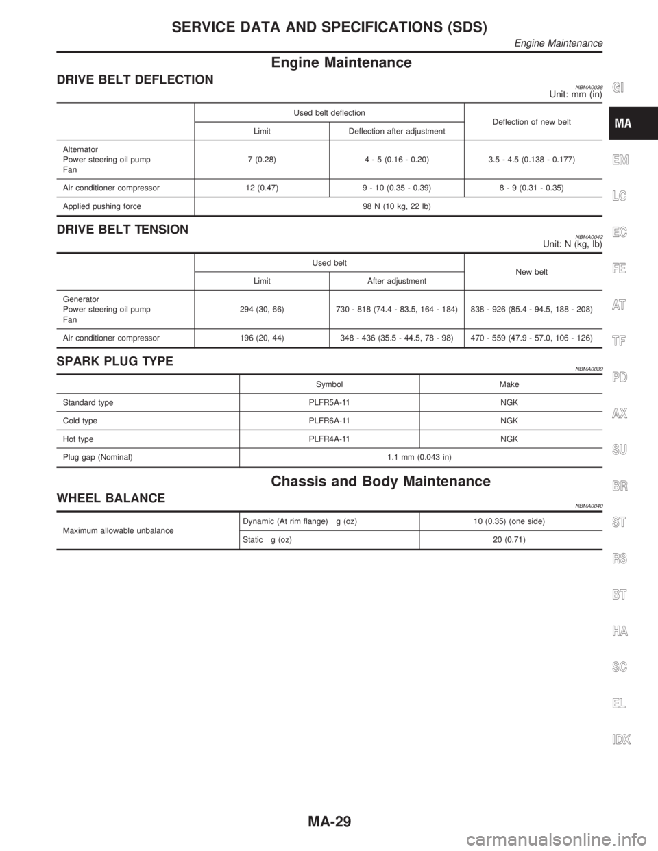
Engine Maintenance
DRIVE BELT DEFLECTIONNBMA0038Unit: mm (in)
Used belt deflection
Deflection of new belt
Limit Deflection after adjustment
Alternator
Power steering oil pump
Fan7 (0.28)4 - 5 (0.16 - 0.20) 3.5 - 4.5 (0.138 - 0.177)
Air conditioner compressor 12 (0.47) 9 - 10 (0.35 - 0.39)8 - 9 (0.31 - 0.35)
Applied pushing force 98 N (10 kg, 22 lb)
DRIVE BELT TENSIONNBMA0042Unit: N (kg, lb)
Used belt
New belt
Limit After adjustment
Generator
Power steering oil pump
Fan294 (30, 66) 730 - 818 (74.4 - 83.5, 164 - 184) 838 - 926 (85.4 - 94.5, 188 - 208)
Air conditioner compressor 196 (20, 44) 348 - 436 (35.5 - 44.5, 78 - 98) 470 - 559 (47.9 - 57.0, 106 - 126)
SPARK PLUG TYPENBMA0039
Symbol Make
Standard type PLFR5A-11 NGK
Cold type PLFR6A-11 NGK
Hot type PLFR4A-11 NGK
Plug gap (Nominal) 1.1 mm (0.043 in)
Chassis and Body Maintenance
WHEEL BALANCENBMA0040
Maximum allowable unbalanceDynamic (At rim flange) g (oz) 10 (0.35) (one side)
Static g (oz) 20 (0.71)
GI
EM
LC
EC
FE
AT
TF
PD
AX
SU
BR
ST
RS
BT
HA
SC
EL
IDX
SERVICE DATA AND SPECIFICATIONS (SDS)
Engine Maintenance
MA-29
Page 2028 of 2395
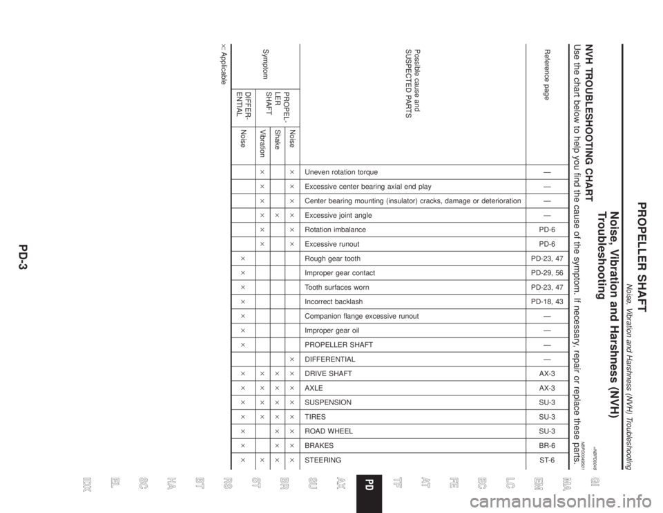
Noise, Vibration and Harshness (NVH)
Troubleshooting
=NBPD0049NVH TROUBLESHOOTING CHARTNBPD0049S01Use the chart below to help you find the cause of the symptom. If necessary, repair or replace these parts.
Reference pageÐ
Ð
Ð
Ð
PD-6
PD-6
PD-23, 47
PD-29, 56
PD-23, 47
PD-18, 43
Ð
Ð
Ð
Ð
AX-3
AX-3
SU-3
SU-3
SU-3
BR-6
ST-6
Possible cause and
SUSPECTED PARTS
Uneven rotation torque
Excessive center bearing axial end play
Center bearing mounting (insulator) cracks, damage or deterioration
Excessive joint angle
Rotation imbalance
Excessive runout
Rough gear tooth
Improper gear contact
Tooth surfaces worn
Incorrect backlash
Companion flange excessive runout
Improper gear oil
PROPELLER SHAFT
DIFFERENTIAL
DRIVE SHAFT
AXLE
SUSPENSION
TIRES
ROAD WHEEL
BRAKES
STEERING
SymptomPROPEL-
LER
SHAFTNoise´´´´´´ ´´´´´´´´
Shake´ ´´´´´´´
Vibration´´´´´´ ´´´´ ´
DIFFER-
ENTIALNoise´´´´´´´ ´´´´´´´
´: Applicable
GI
MA
EM
LC
EC
FE
AT
TF
AX
SU
BR
ST
RS
BT
HA
SC
EL
IDX
PROPELLER SHAFT
Noise, Vibration and Harshness (NVH) Troubleshooting
PD-3
Page 2099 of 2395
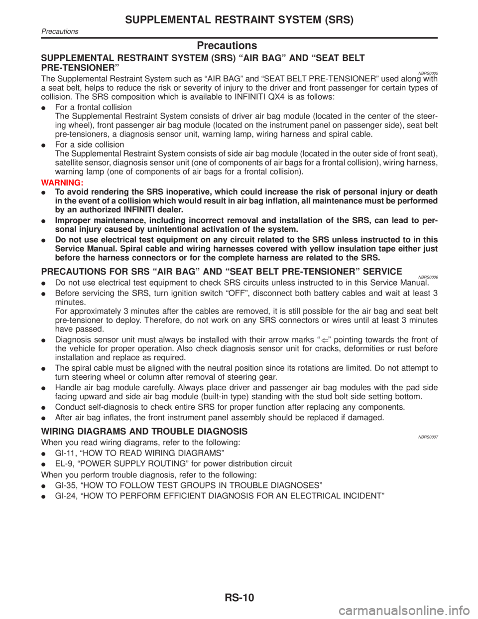
Precautions
SUPPLEMENTAL RESTRAINT SYSTEM (SRS) ªAIR BAGº AND ªSEAT BELT
PRE-TENSIONERº
NBRS0005The Supplemental Restraint System such as ªAIR BAGº and ªSEAT BELT PRE-TENSIONERº used along with
a seat belt, helps to reduce the risk or severity of injury to the driver and front passenger for certain types of
collision. The SRS composition which is available to INFINITI QX4 is as follows:
IFor a frontal collision
The Supplemental Restraint System consists of driver air bag module (located in the center of the steer-
ing wheel), front passenger air bag module (located on the instrument panel on passenger side), seat belt
pre-tensioners, a diagnosis sensor unit, warning lamp, wiring harness and spiral cable.
IFor a side collision
The Supplemental Restraint System consists of side air bag module (located in the outer side of front seat),
satellite sensor, diagnosis sensor unit (one of components of air bags for a frontal collision), wiring harness,
warning lamp (one of components of air bags for a frontal collision).
WARNING:
ITo avoid rendering the SRS inoperative, which could increase the risk of personal injury or death
in the event of a collision which would result in air bag inflation, all maintenance must be performed
by an authorized INFINITI dealer.
IImproper maintenance, including incorrect removal and installation of the SRS, can lead to per-
sonal injury caused by unintentional activation of the system.
IDo not use electrical test equipment on any circuit related to the SRS unless instructed to in this
Service Manual. Spiral cable and wiring harnesses covered with yellow insulation tape either just
before the harness connectors or for the complete harness are related to the SRS.
PRECAUTIONS FOR SRS ªAIR BAGº AND ªSEAT BELT PRE-TENSIONERº SERVICENBRS0006IDo not use electrical test equipment to check SRS circuits unless instructed to in this Service Manual.
IBefore servicing the SRS, turn ignition switch ªOFFº, disconnect both battery cables and wait at least 3
minutes.
For approximately 3 minutes after the cables are removed, it is still possible for the air bag and seat belt
pre-tensioner to deploy. Therefore, do not work on any SRS connectors or wires until at least 3 minutes
have passed.
IDiagnosis sensor unit must always be installed with their arrow marks ªgº pointing towards the front of
the vehicle for proper operation. Also check diagnosis sensor unit for cracks, deformities or rust before
installation and replace as required.
IThe spiral cable must be aligned with the neutral position since its rotations are limited. Do not attempt to
turn steering wheel or column after removal of steering gear.
IHandle air bag module carefully. Always place driver and passenger air bag modules with the pad side
facing upward and side air bag module (built-in type) standing with the stud bolt side setting bottom.
IConduct self-diagnosis to check entire SRS for proper function after replacing any components.
IAfter air bag inflates, the front instrument panel assembly should be replaced if damaged.
WIRING DIAGRAMS AND TROUBLE DIAGNOSISNBRS0007When you read wiring diagrams, refer to the following:
IGI-11, ªHOW TO READ WIRING DIAGRAMSº
IEL-9, ªPOWER SUPPLY ROUTINGº for power distribution circuit
When you perform trouble diagnosis, refer to the following:
IGI-35, ªHOW TO FOLLOW TEST GROUPS IN TROUBLE DIAGNOSESº
IGI-24, ªHOW TO PERFORM EFFICIENT DIAGNOSIS FOR AN ELECTRICAL INCIDENTº
SUPPLEMENTAL RESTRAINT SYSTEM (SRS)
Precautions
RS-10