Page 2194 of 2395
Disassembly and AssemblyNBST0018
SST845C
1. Combination switch
2. Lock nut
3. Jacket tube assembly4. Tilt lever
5. Tilt spring
6. Steering column shaft assembly7. Band
8. Jacket tube bracket insulator
assembly
9. Hole cover
SST490C
IWhen disassembling and assembling, unlock steering lock
with key.
IInstall lock nut on steering column shaft and tighten the nut to
specification.
: 25 - 34 N´m (2.5 - 3.5 kg-m, 18 - 25 ft-lb)
SST742A
ISteering lock
a) Break self-shear type screws with a drill or other appropriate
tool.
b) Install new self-shear type screws and then cut off self-shear
type screw heads.
GI
MA
EM
LC
EC
FE
AT
TF
PD
AX
SU
BR
RS
BT
HA
SC
EL
IDX
STEERING WHEEL AND STEERING COLUMN
Disassembly and Assembly
ST-13
Page 2195 of 2395
SST606C
SST607C
InspectionNBST0019IWhen steering wheel does not turn smoothly, check the steer-
ing column as follows and replace damaged parts.
a) Check column bearings for damage and unevenness. Lubri-
cate with recommended multi-purpose grease or replace steer-
ing column as an assembly, if necessary.
b) Check steering column lower shaft for deformation and break-
age. Replace if necessary.
IWhen the vehicle comes into a light collision, check length ªL
1º,
ªL
2º and ªL3º.
Steering column length ªL
1º:
716.7 - 718.7 mm (28.22 - 28.30 in)
Steering column lower shaft length ªL
2º:
178 - 180 mm (7.01 - 7.09 in)
Steering column upper joint length ªL
3º:
430.7 - 432.7 mm (16.96 - 17.04 in)
If out of the specifications, replace steering column upper joint
or steering column as an assembly.
SST582BE
TILT MECHANISMNBST0019S01After installing steering column, check tilt mechanism operation.
STEERING WHEEL AND STEERING COLUMN
Inspection
ST-14
Page 2196 of 2395
RemovalNBST0021
SST846C
1. Power steering gear assembly
2. Steering column lower joint3. Transfer gear assembly 4. Steering column upper joint
SST609C
1. Set wheels in the straight-ahead position.
2. Straight-forward position is indicated by a protrusion on the
power steering gear rear cover cap and matching mark on the
rear housing.
SST610C
3. Remove steering column upper and lower joint from transfer
gear.
4. Remove transfer gear assembly.
GI
MA
EM
LC
EC
FE
AT
TF
PD
AX
SU
BR
RS
BT
HA
SC
EL
IDX
STEERING TRANSFER GEAR
Removal
ST-15
Page 2197 of 2395
SST847C
InstallationNBST00221. Set wheels in the straight-ahead position.
2. Install transfer gear assembly.
3. Install column lower joint while aligning groove with protrusions
on the steering gear rear cover cap.
4. Tighten bolt while aligning groove on steering gear. Before
tightening bolt, ensure it is inserted correctly.
SST848C
5. When attaching steering column upper and lower joint to trans-
fer gear, it must be positioned as shown in figure at left.
SST707CA
InspectionNBST0024Do not disassemble steering transfer gear assembly.
ICheck that steering transfer gear assembly operates smoothly.
Also check for grease leakage, deformation and damage.
Replace steering transfer gear assembly if necessary.
ICheck rotating torque at input shaft in 360É and in both direc-
tions.
Rotating torque:
0.25 - 0.69 N´m (2.5 - 7.0 kg-cm, 2.2 - 6.1 in-lb)
If rotating torque is out of specification, replace steering trans-
fer gear assembly.
STEERING TRANSFER GEAR
Installation
ST-16
Page 2199 of 2395

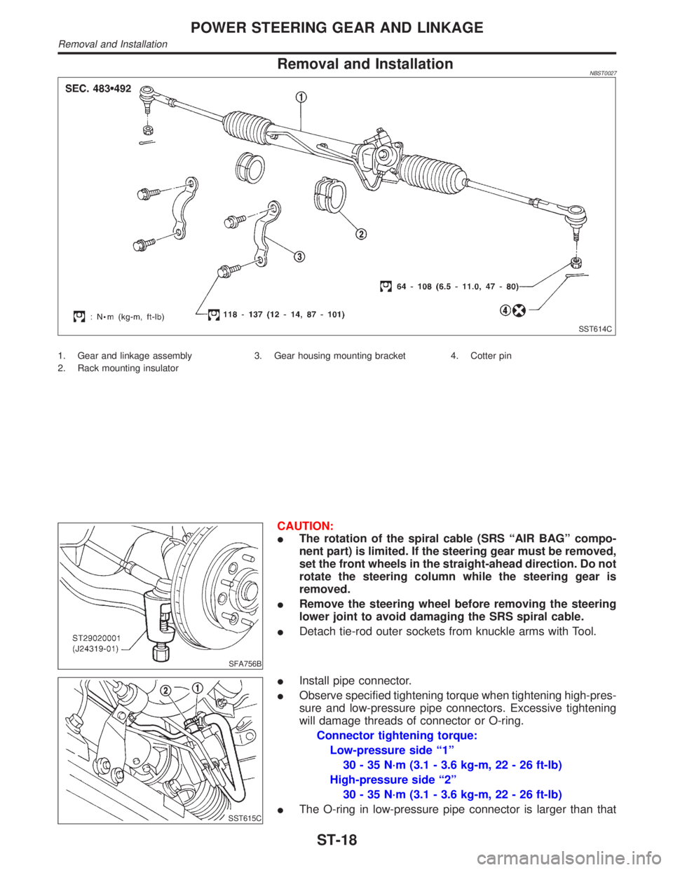
Removal and InstallationNBST0027
SST614C
1. Gear and linkage assembly
2. Rack mounting insulator3. Gear housing mounting bracket 4. Cotter pin
SFA756B
CAUTION:
IThe rotation of the spiral cable (SRS ªAIR BAGº compo-
nent part) is limited. If the steering gear must be removed,
set the front wheels in the straight-ahead direction. Do not
rotate the steering column while the steering gear is
removed.
IRemove the steering wheel before removing the steering
lower joint to avoid damaging the SRS spiral cable.
IDetach tie-rod outer sockets from knuckle arms with Tool.
SST615C
IInstall pipe connector.
IObserve specified tightening torque when tightening high-pres-
sure and low-pressure pipe connectors. Excessive tightening
will damage threads of connector or O-ring.
Connector tightening torque:
Low-pressure side ª1º
30 - 35 N´m (3.1 - 3.6 kg-m, 22 - 26 ft-lb)
High-pressure side ª2º
30 - 35 N´m (3.1 - 3.6 kg-m, 22 - 26 ft-lb)
IThe O-ring in low-pressure pipe connector is larger than that
POWER STEERING GEAR AND LINKAGE
Removal and Installation
ST-18
Page 2200 of 2395

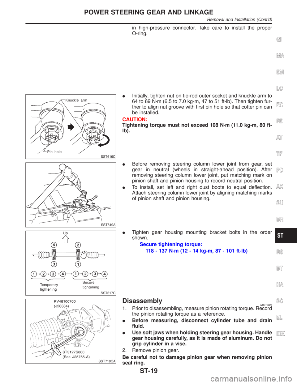
in high-pressure connector. Take care to install the proper
O-ring.
SST616C
IInitially, tighten nut on tie-rod outer socket and knuckle arm to
64 to 69 N´m (6.5 to 7.0 kg-m, 47 to 51 ft-lb). Then tighten fur-
ther to align nut groove with first pin hole so that cotter pin can
be installed.
CAUTION:
Tightening torque must not exceed 108 N´m (11.0 kg-m, 80 ft-
lb).
SST819A
IBefore removing steering column lower joint from gear, set
gear in neutral (wheels in straight-ahead position). After
removing steering column lower joint, put matching mark on
pinion shaft and pinion housing to record neutral position.
ITo install, set left and right dust boots to equal deflection.
Attach steering column lower joint by aligning matching marks
of pinion shaft and pinion housing.
SST617C
ITighten gear housing mounting bracket bolts in the order
shown.
Secure tightening torque:
118 - 137 N´m (12 - 14 kg-m, 87 - 101 ft-lb)
SST718CA
DisassemblyNBST00281. Prior to disassembling, measure pinion rotating torque. Record
the pinion rotating torque as a reference.
IBefore measuring, disconnect cylinder tube and drain
fluid.
IUse soft jaws when holding steering gear housing. Handle
gear housing carefully, as it is made of aluminum. Do not
grip cylinder in a vise.
2. Remove pinion gear.
Be careful not to damage pinion gear when removing pinion
seal ring.
GI
MA
EM
LC
EC
FE
AT
TF
PD
AX
SU
BR
RS
BT
HA
SC
EL
IDX
POWER STEERING GEAR AND LINKAGE
Removal and Installation (Cont'd)
ST-19
Page 2213 of 2395
General SpecificationsNBST0037
Applied modelAll
Steering modelPower steering
Steering gear typePR32K
Steering overall gear ratio 17.2
Turns of steering wheel
(Lock to lock)3.09
Steering column type Collapsible, tilt
Steering WheelNBST0038Unit: mm (in)
Steering wheel axial play0 (0)
Steering wheel play35 (1.38) or less
Movement of gear housing±2(±0.08) or less
Steering ColumnNBST0039Unit: mm (in)
Steering column length ªL1º 716.7 - 718.7 (28.22 - 28.30)
Steering column lower shaft length ªL
2º 178 - 180 (7.01 - 7.09)
Steering column upper joint length ªL
3º 430.7 - 432.7 (16.96 - 17.04)
SST739C
Steering Transfer GearNBST0041
Rotating torque0.25 - 0.69 N´m (2.5 - 7.0 kg-cm, 2.2 - 6.1 in-lb)
SERVICE DATA AND SPECIFICATIONS (SDS)
General Specifications
ST-32
Page 2214 of 2395

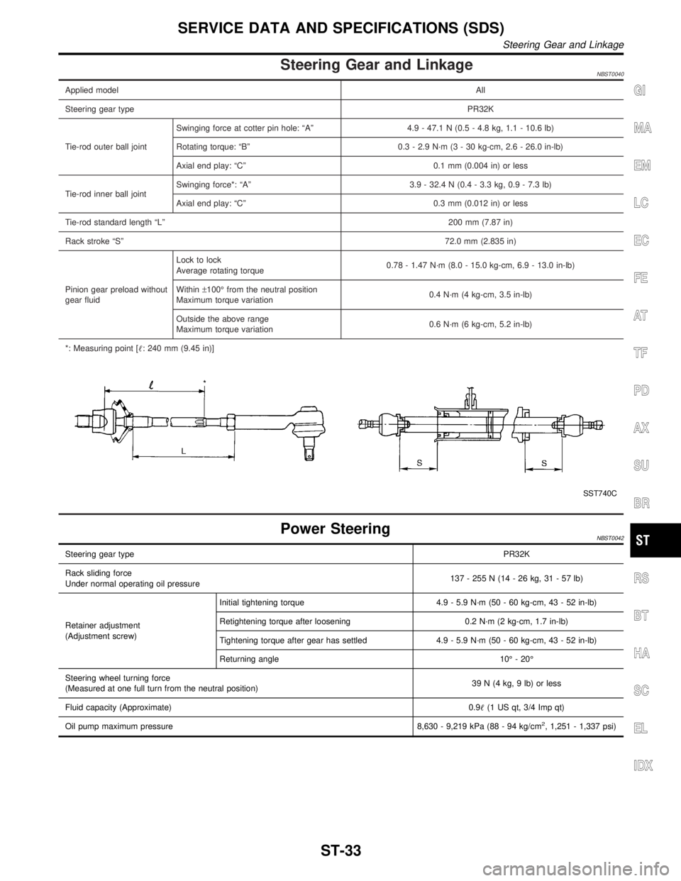
Steering Gear and LinkageNBST0040
Applied modelAll
Steering gear typePR32K
Tie-rod outer ball jointSwinging force at cotter pin hole: ªAº 4.9 - 47.1 N (0.5 - 4.8 kg, 1.1 - 10.6 lb)
Rotating torque: ªBº 0.3 - 2.9 N´m (3 - 30 kg-cm, 2.6 - 26.0 in-lb)
Axial end play: ªCº 0.1 mm (0.004 in) or less
Tie-rod inner ball jointSwinging force*: ªAº 3.9 - 32.4 N (0.4 - 3.3 kg, 0.9 - 7.3 lb)
Axial end play: ªCº 0.3 mm (0.012 in) or less
Tie-rod standard length ªLº200 mm (7.87 in)
Rack stroke ªSº72.0 mm (2.835 in)
Pinion gear preload without
gear fluidLock to lock
Average rotating torque0.78 - 1.47 N´m (8.0 - 15.0 kg-cm, 6.9 - 13.0 in-lb)
Within±100É from the neutral position
Maximum torque variation0.4 N´m (4 kg-cm, 3.5 in-lb)
Outside the above range
Maximum torque variation0.6 N´m (6 kg-cm, 5.2 in-lb)
*: Measuring point [: 240 mm (9.45 in)]
SST740C
Power SteeringNBST0042
Steering gear typePR32K
Rack sliding force
Under normal operating oil pressure137 - 255 N (14 - 26 kg, 31 - 57 lb)
Retainer adjustment
(Adjustment screw)Initial tightening torque 4.9 - 5.9 N´m (50 - 60 kg-cm, 43 - 52 in-lb)
Retightening torque after loosening 0.2 N´m (2 kg-cm, 1.7 in-lb)
Tightening torque after gear has settled 4.9 - 5.9 N´m (50 - 60 kg-cm, 43 - 52 in-lb)
Returning angle 10É - 20É
Steering wheel turning force
(Measured at one full turn from the neutral position)39 N (4 kg, 9 lb) or less
Fluid capacity (Approximate)0.9(1 US qt, 3/4 Imp qt)
Oil pump maximum pressure 8,630 - 9,219 kPa (88 - 94 kg/cm
2, 1,251 - 1,337 psi)
GI
MA
EM
LC
EC
FE
AT
TF
PD
AX
SU
BR
RS
BT
HA
SC
EL
IDX
SERVICE DATA AND SPECIFICATIONS (SDS)
Steering Gear and Linkage
ST-33