Page 2176 of 2395
DIAGNOSTIC PROCEDURE 1NBSC0020S03Check ªLº Terminal CircuitNBSC0020S0301
1 CHECK ªLº TERMINAL CONNECTION
Check to see if ªLº terminal is clean and tight.
OK or NG
OK©GO TO 2.
NG©Repair ªLº terminal connection. Confirm repair by performing complete Battery/Starting/
Charging system test.
2 CHECK ªLº TERMINAL CIRCUIT
1. Disconnect E106 connector from alternator.
2. Apply ground to E106 connector terminal 1 with the ignition switch in the ON position.
SEL424X
OK or NG
OK©Replace the alternator. Confirm repair by performing complete Battery/Starting/Charging
system test.
NG©Check the following.
I10A fuse [No. 8, located in fuse block (J/B)]
ICHARGE lamp
IHarness for open or short between combination meter and fuse
IHarness for open or short between combination meter and alternator
GI
MA
EM
LC
EC
FE
AT
TF
PD
AX
SU
BR
ST
RS
BT
HA
EL
IDX
CHARGING SYSTEM
Trouble Diagnoses with Battery/Starting/Charging System Tester (Cont'd)
SC-25
Page 2238 of 2395

Supplemental Restraint System (SRS) ªAIR
BAGº and ªSEAT BELT PRE-TENSIONERº
NBTF0001The Supplemental Restraint System such as ªAIR BAGº and ªSEAT BELT PRE-TENSIONERº used along with
a seat belt, helps to reduce the risk or severity of injury to the driver and front passenger for certain types of
collision. The SRS system composition which is available to INFINITI QX4 is as follows:
IFor a frontal collision
The Supplemental Restraint System consists of driver air bag module (located in the center of the steer-
ing wheel), front passenger air bag module (located on the instrument panel on passenger side), seat belt
pre-tensioners, a diagnosis sensor unit, warning lamp, wiring harness and spiral cable.
IFor a side collision
The Supplemental Restraint System consists of side air bag module (located in the outer side of front seat),
satellite sensor, diagnosis sensor unit (one of components of air bags for a frontal collision), wiring harness,
warning lamp (one of components of air bags for a frontal collision).
Information necessary to service the system safely is included in theRSsection of this Service Manual.
WARNING:
ITo avoid rendering the SRS inoperative, which could increase the risk of personal injury or death
in the event of a collision which would result in air bag inflation, all maintenance must be performed
by an authorized INFINITI dealer.
IImproper maintenance, including incorrect removal and installation of the SRS, can lead to per-
sonal injury caused by unintentional activation of the system. For removal of Spiral Cable and Air
Bag Module, see the RS section.
IDo not use electrical test equipment on any circuit related to the SRS unless instructed to in this
Service Manual. Spiral cable and wiring harnesses covered with yellow insulation tape either just
before the harness connectors or for the complete harness are related to the SRS.
SEF289H
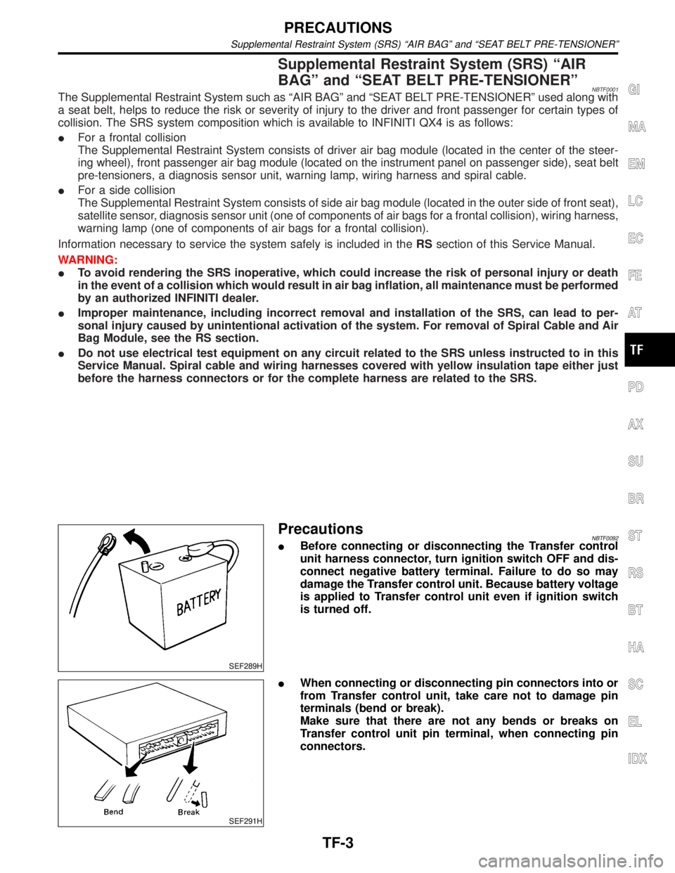
PrecautionsNBTF0092IBefore connecting or disconnecting the Transfer control
unit harness connector, turn ignition switch OFF and dis-
connect negative battery terminal. Failure to do so may
damage the Transfer control unit. Because battery voltage
is applied to Transfer control unit even if ignition switch
is turned off.
SEF291H
IWhen connecting or disconnecting pin connectors into or
from Transfer control unit, take care not to damage pin
terminals (bend or break).
Make sure that there are not any bends or breaks on
Transfer control unit pin terminal, when connecting pin
connectors.
GI
MA
EM
LC
EC
FE
AT
PD
AX
SU
BR
ST
RS
BT
HA
SC
EL
IDX
PRECAUTIONS
Supplemental Restraint System (SRS) ªAIR BAGº and ªSEAT BELT PRE-TENSIONERº
TF-3
Page 2299 of 2395

Diagnostic ProcedureNBTF0020
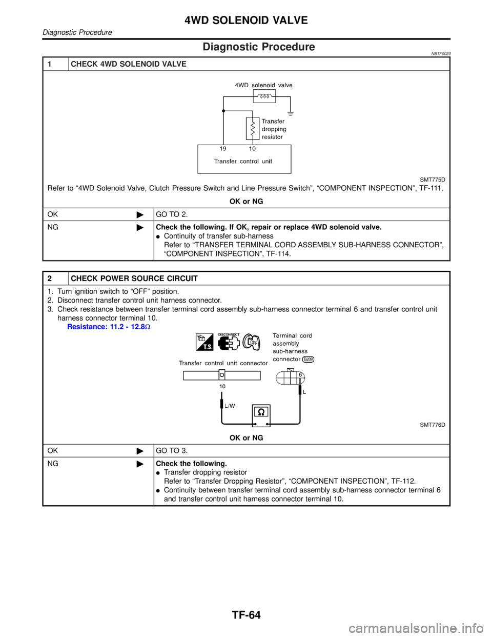
1 CHECK 4WD SOLENOID VALVE
SMT775D
Refer to ª4WD Solenoid Valve, Clutch Pressure Switch and Line Pressure Switchº, ªCOMPONENT INSPECTIONº, TF-111.
OK or NG
OK©GO TO 2.
NG©Check the following. If OK, repair or replace 4WD solenoid valve.
IContinuity of transfer sub-harness
Refer to ªTRANSFER TERMINAL CORD ASSEMBLY SUB-HARNESS CONNECTORº,
ªCOMPONENT INSPECTIONº, TF-114.
2 CHECK POWER SOURCE CIRCUIT
1. Turn ignition switch to ªOFFº position.
2. Disconnect transfer control unit harness connector.
3. Check resistance between transfer terminal cord assembly sub-harness connector terminal 6 and transfer control unit
harness connector terminal 10.
Resistance: 11.2 - 12.8W
SMT776D
OK or NG
OK©GO TO 3.
NG©Check the following.
ITransfer dropping resistor
Refer to ªTransfer Dropping Resistorº, ªCOMPONENT INSPECTIONº, TF-112.
IContinuity between transfer terminal cord assembly sub-harness connector terminal 6
and transfer control unit harness connector terminal 10.
4WD SOLENOID VALVE
Diagnostic Procedure
TF-64
Page 2300 of 2395

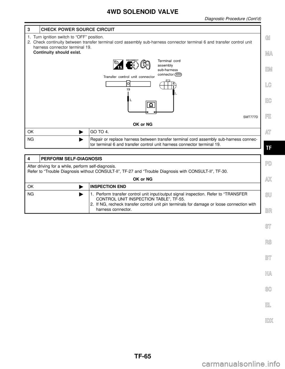
3 CHECK POWER SOURCE CIRCUIT
1. Turn ignition switch to ªOFFº position.
2. Check continuity between transfer terminal cord assembly sub-harness connector terminal 6 and transfer control unit
harness connector terminal 19.
Continuity should exist.
SMT777D
OK or NG
OK©GO TO 4.
NG©Repair or replace harness between transfer terminal cord assembly sub-harness connec-
tor terminal 6 and transfer control unit harness connector terminal 19.
4 PERFORM SELF-DIAGNOSIS
After driving for a while, perform self-diagnosis.
Refer to ªTrouble Diagnosis without CONSULT-IIº, TF-27 and ªTrouble Diagnosis with CONSULT-IIº, TF-30.
OK or NG
OK©INSPECTION END
NG©1. Perform transfer control unit input/output signal inspection. Refer to ªTRANSFER
CONTROL UNIT INSPECTION TABLEº, TF-55.
2. If NG, recheck transfer control unit pin terminals for damage or loose connection with
harness connector.
GI
MA
EM
LC
EC
FE
AT
PD
AX
SU
BR
ST
RS
BT
HA
SC
EL
IDX
4WD SOLENOID VALVE
Diagnostic Procedure (Cont'd)
TF-65
Page 2303 of 2395
3 CHECK 4WD SHIFT SWITCH POWER SOURCE
1. Disconnect 4WD shift switch harness connector.
2. Turn ignition switch to ªONº position.
3. Check voltage between 4WD shift switch harness connector terminal 1 and body ground.
Voltage: Battery voltage
SMT852D
OK or NG
OK©GO TO 4.
NG©Check the following.
INo. 18 fuse (10A)
IContinuity between ignition switch and 4WD shift switch
2-4WD SHIFT SOLENOID VALVE AND 4WD SHIFT SWITCH
Diagnostic Procedure (Cont'd)
TF-68
Page 2304 of 2395

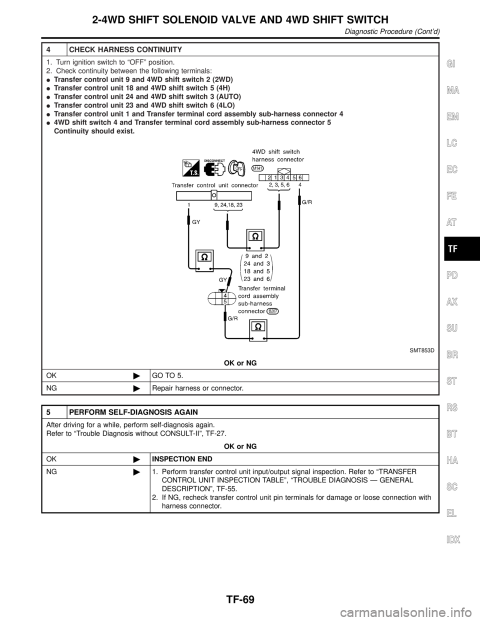
4 CHECK HARNESS CONTINUITY
1. Turn ignition switch to ªOFFº position.
2. Check continuity between the following terminals:
ITransfer control unit 9 and 4WD shift switch 2 (2WD)
ITransfer control unit 18 and 4WD shift switch 5 (4H)
ITransfer control unit 24 and 4WD shift switch 3 (AUTO)
ITransfer control unit 23 and 4WD shift switch 6 (4LO)
ITransfer control unit 1 and Transfer terminal cord assembly sub-harness connector 4
I4WD shift switch 4 and Transfer terminal cord assembly sub-harness connector 5
Continuity should exist.
SMT853D
OK or NG
OK©GO TO 5.
NG©Repair harness or connector.
5 PERFORM SELF-DIAGNOSIS AGAIN
After driving for a while, perform self-diagnosis again.
Refer to ªTrouble Diagnosis without CONSULT-IIº, TF-27.
OK or NG
OK©INSPECTION END
NG©1. Perform transfer control unit input/output signal inspection. Refer to ªTRANSFER
CONTROL UNIT INSPECTION TABLEº, ªTROUBLE DIAGNOSIS Ð GENERAL
DESCRIPTIONº, TF-55.
2. If NG, recheck transfer control unit pin terminals for damage or loose connection with
harness connector.
GI
MA
EM
LC
EC
FE
AT
PD
AX
SU
BR
ST
RS
BT
HA
SC
EL
IDX
2-4WD SHIFT SOLENOID VALVE AND 4WD SHIFT SWITCH
Diagnostic Procedure (Cont'd)
TF-69
Page 2306 of 2395
4 CHECK TRANSFER MOTOR RELAY POWER SOURCE
1. Disconnect transfer motor relay harness connector.
2. Turn ignition switch to ªONº position.
3. Check voltage between transfer motor relay harness connector terminals 1, 3 and body ground.
Voltage: Battery voltage
SMT854DA
OK or NG
OK©GO TO 5.
NG©Check the following.
INo. 55 fuse (20A)
INo. 18 fuse (10A)
IHarness continuity between fuse and transfer motor relay
GI
MA
EM
LC
EC
FE
AT
PD
AX
SU
BR
ST
RS
BT
HA
SC
EL
IDX
TRANSFER MOTOR AND TRANSFER MOTOR RELAY
Diagnostic Procedure (Cont'd)
TF-71
Page 2307 of 2395
5 CHECK HARNESS CONTINUITY
1. Turn ignition switch to ªOFFº position.
2. Check continuity between the following terminals.
ITransfer control unit 41 and Transfer motor 14
ITransfer control unit 41 and Transfer motor relay 2
ITransfer control unit 14 and Transfer motor relay 4
ITransfer motor 15 and body ground
Continuity should exist.
SMT855DA
OK or NG
OK©GO TO 6.
NG©Repair or replace harness or connector.
6 PERFORM SELF-DIAGNOSIS AGAIN
After driving for a while, perform self-diagnosis again.
Refer to ªTrouble Diagnosis without CONSULT-IIº, TF-27 and ªTrouble Diagnosis with CONSULT-IIº, TF-30.
OK or NG
OK©INSPECTION END
NG©1. Perform transfer control unit input/output signal inspection. Refer to ªTRANSFER
CONTROL UNIT INSPECTION TABLEº, ªTROUBLE DIAGNOSIS Ð GENERAL
DESCRIPTIONº, TF-55.
2. If NG, recheck transfer control unit pin terminals for damage or loose connection with
harness connector.
TRANSFER MOTOR AND TRANSFER MOTOR RELAY
Diagnostic Procedure (Cont'd)
TF-72