Page 2131 of 2395
![INFINITI QX4 2001 Factory Service Manual Diagnostic item ExplanationRepair order
ªRecheck SRS at each replace-
ment.º
PRE-TEN FRONT LH
[OPEN/VB-SHORT]IThe circuit for front LH pre-tensioner is open or shorted to
some power supply circuit.1 INFINITI QX4 2001 Factory Service Manual Diagnostic item ExplanationRepair order
ªRecheck SRS at each replace-
ment.º
PRE-TEN FRONT LH
[OPEN/VB-SHORT]IThe circuit for front LH pre-tensioner is open or shorted to
some power supply circuit.1](/manual-img/42/57027/w960_57027-2130.png)
Diagnostic item ExplanationRepair order
ªRecheck SRS at each replace-
ment.º
PRE-TEN FRONT LH
[OPEN/VB-SHORT]IThe circuit for front LH pre-tensioner is open or shorted to
some power supply circuit.1. Visually check the wiring harness
connections.
2. Replace the harness if it has visible
damage.
3. Replace front LH seat belt.
(Before disposing, it must be deacti-
vated.)
4. Replace the diagnosis sensor unit.
5. Replace the related harness. PRE-TEN FRONT LH
[GND-SHORT]IThe circuit for front LH pre-tensioner is shorted to ground.
PRE-TEN FRONT RH
[OPEN/VB-SHORT]IThe circuit for front RH pre-tensioner is open or shorted to
some power supply circuit.1. Visually check the wiring harness
connections.
2. Replace the harness if it has visible
damage.
3. Replace front RH seat belt.
(Before disposing, it must be deacti-
vated.)
4. Replace the diagnosis sensor unit.
5. Replace the related harness. PRE-TEN FRONT RH
[GND-SHORT]IThe circuit for front RH pre-tensioner is shorted to ground.
CONTROL UNITIDiagnosis sensor unit is malfunctioning. 1. Visually check the wiring harness
connection.
2. Replace the diagnosis sensor unit.
* Follow the procedures in numerical order when repairing malfunctioning parts. Confirm whether malfunction is eliminated
using the air bag warning lamp or CONSULT-II each time repair is finished. If malfunction is still observed, proceed to the next
step. When malfunction is eliminated, further repair work is not required.
SRS844
DIAGNOSTIC PROCEDURE 3NBRS0045S02Final checking after repairing SRS by using CONSULT-II Ð
Diagnosis mode
1. After repairing SRS, connect both battery cables.
2. Connect CONSULT-II to Data link connector.
3. Turn ignition switch from ªOFFº to ªONº.
SRS695
4. Touch ªSTARTº.
SUPPLEMENTAL RESTRAINT SYSTEM (SRS)
Trouble Diagnoses with CONSULT-II (Cont'd)
RS-42
Page 2135 of 2395

SRS704
9. Diagnostic code is displayed on ªTROUBLE DIAG RECORDº.
10. Touch ªPRINTº.
11. Compare diagnostic codes to ªIntermittent Malfunction Diag-
nostic Code Chartº, page RS-46.
12. Touch ªBACKº key of CONSULT-II until ªSELECT SYSTEMº
appears.
13. Turn ignition switch ªOFFº, then turn off and disconnect
CONSULT-II, and disconnect both battery cables.
14. Repair the system as outlined by the ªRepair orderº in ªInter-
mittent Malfunction Diagnostic Code Chartº, that corresponds
to the self-diagnostic result. For replacement procedure of
component parts, refer to RS-15.
15. Go to DIAGNOSTIC PROCEDURE 3, page RS-42, for final
checking.
Intermittent Malfunction Diagnostic Code Chart (ªSELF-
DIAG [PAST]º or ªTROUBLE DIAG RECORDº)
NBRS0045S0401
Diagnostic item Explanation Repair order
NO DTC IS
DETECTED.When malfunction is
indicated by the ªAIR
BAGº warning lamp in
User modeILow battery voltage (Less than 9V)IGo to DIAGNOSTIC PROCEDURE
3 (RS-42) after charging battery.
INo malfunction is detected.IGo to DIAGNOSTIC PROCEDURE
3 (RS-42).
AIRBAG MODULE
[OPEN]IDriver's air bag module circuit is open. (including the spiral
cable)1. Visually check the wiring harness
connection.
2. Replace the harness if it has visible
damage.
3. If the harness check result is OK,
replace driver's air bag module
(Before disposal of it, it must be
deployed.), diagnosis sensor unit
and spiral cable. AIRBAG MODULE
[VB-SHORT]IDriver's air bag module circuit is shorted to some power sup-
ply circuit. (including the spiral cable)
AIRBAG MODULE
[GND-SHORT]IDriver's air bag module circuit is shorted to ground. (including
the spiral cable)
AIRBAG MODULE
[SHORT]IDriver's air bag module circuits are shorted to each other.
ASSIST A/B MODULE
[VB-SHORT]IFront passenger air bag module circuit is shorted to some
power supply circuit.1. Visually check the wiring harness
connection.
2. Replace the harness if it has visible
damage.
3. If the harness check result is OK,
replace front air bag module
(Before disposal of it, it must be
deployed.), and diagnosis sensor
unit. ASSIST A/B MODULE
[OPEN]IFront passenger air bag module circuit is open.
ASSIST A/B MODULE
[GND-SHORT]IFront passenger air bag module circuit is shorted to ground.
ASSIST A/B MODULE
[SHORT]IFront passenger air bag module circuits are shorted to each
other.
SUPPLEMENTAL RESTRAINT SYSTEM (SRS)
Trouble Diagnoses with CONSULT-II (Cont'd)
RS-46
Page 2137 of 2395

Diagnostic item Explanation Repair order
CONTROL UNITIDiagnosis sensor unit is malfunctioning. 1. Visually check the wiring harness
connection.
2. Replace the harness if it has visible
damage.
3. If the harness check is OK, replace
the diagnosis sensor unit.
* Follow the procedures in numerical order when repairing malfunctioning parts, then make the final system check.
SRS800
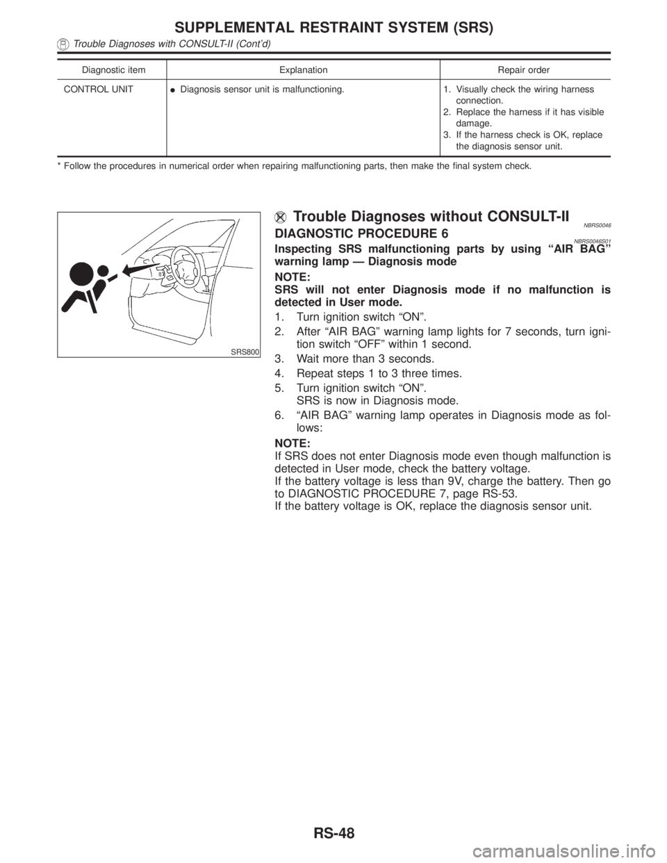
Trouble Diagnoses without CONSULT-IINBRS0046DIAGNOSTIC PROCEDURE 6NBRS0046S01Inspecting SRS malfunctioning parts by using ªAIR BAGº
warning lamp Ð Diagnosis mode
NOTE:
SRS will not enter Diagnosis mode if no malfunction is
detected in User mode.
1. Turn ignition switch ªONº.
2. After ªAIR BAGº warning lamp lights for 7 seconds, turn igni-
tion switch ªOFFº within 1 second.
3. Wait more than 3 seconds.
4. Repeat steps 1 to 3 three times.
5. Turn ignition switch ªONº.
SRS is now in Diagnosis mode.
6. ªAIR BAGº warning lamp operates in Diagnosis mode as fol-
lows:
NOTE:
If SRS does not enter Diagnosis mode even though malfunction is
detected in User mode, check the battery voltage.
If the battery voltage is less than 9V, charge the battery. Then go
to DIAGNOSTIC PROCEDURE 7, page RS-53.
If the battery voltage is OK, replace the diagnosis sensor unit.
SUPPLEMENTAL RESTRAINT SYSTEM (SRS)
Trouble Diagnoses with CONSULT-II (Cont'd)
RS-48
Page 2142 of 2395

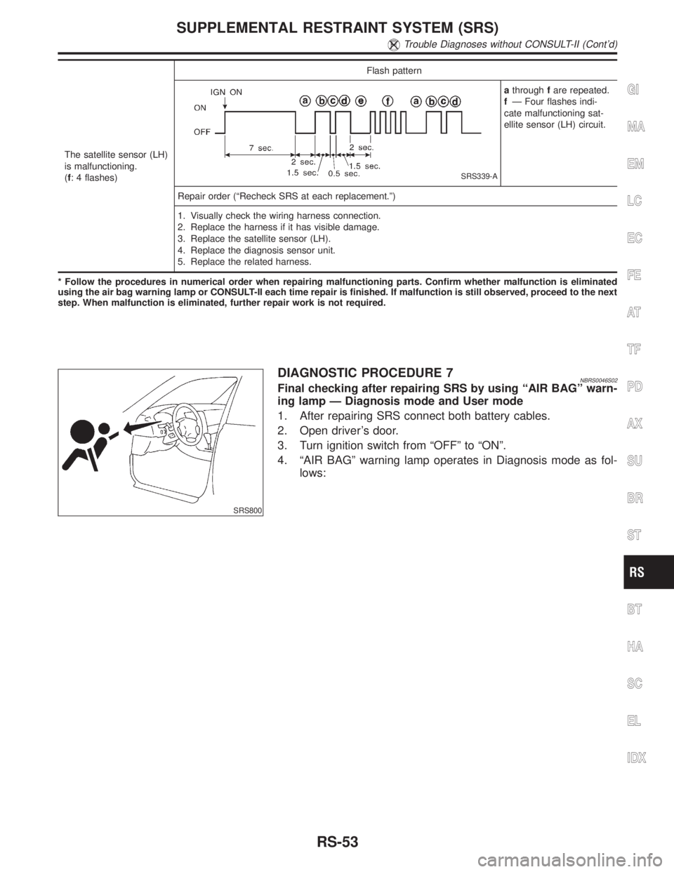
The satellite sensor (LH)
is malfunctioning.
(f: 4 flashes)Flash pattern
SRS339-A
athroughfare repeated.
fÐ Four flashes indi-
cate malfunctioning sat-
ellite sensor (LH) circuit.
Repair order (ªRecheck SRS at each replacement.º)
1. Visually check the wiring harness connection.
2. Replace the harness if it has visible damage.
3. Replace the satellite sensor (LH).
4. Replace the diagnosis sensor unit.
5. Replace the related harness.
* Follow the procedures in numerical order when repairing malfunctioning parts. Confirm whether malfunction is eliminated
using the air bag warning lamp or CONSULT-II each time repair is finished. If malfunction is still observed, proceed to the next
step. When malfunction is eliminated, further repair work is not required.
SRS800
DIAGNOSTIC PROCEDURE 7NBRS0046S02Final checking after repairing SRS by using ªAIR BAGº warn-
ing lamp Ð Diagnosis mode and User mode
1. After repairing SRS connect both battery cables.
2. Open driver's door.
3. Turn ignition switch from ªOFFº to ªONº.
4. ªAIR BAGº warning lamp operates in Diagnosis mode as fol-
lows:
GI
MA
EM
LC
EC
FE
AT
TF
PD
AX
SU
BR
ST
BT
HA
SC
EL
IDX
SUPPLEMENTAL RESTRAINT SYSTEM (SRS)
Trouble Diagnoses without CONSULT-II (Cont'd)
RS-53
Page 2145 of 2395
Trouble Diagnoses: ªAIR BAGº Warning Lamp
Does Not Turn Off
=NBRS0047DIAGNOSTIC PROCEDURE 9NBRS0047S01
1 SEE THE DEPLOYMENT OF AIR BAG MODULE
Is air bag module deployed?
YesorNo
Ye s©Refer to COLLISION DIAGNOSIS (RS-59).
No©GO TO 2.
2 CHECK AIR BAG FUSE
Is SRS ªAir Bagº fuse OK?
SRS577
OK or NG
OK©GO TO 4.
NG©GO TO 3.
3 CHECK AIR BAG FUSE AGAIN
Replace ªAIR BAGº fuse and turn ignition switch ON.
Is ªAIR BAGº fuse blown again?
Ye s©Repair main harness and/or replace air bag harness.
No©INSPECTION END
SUPPLEMENTAL RESTRAINT SYSTEM (SRS)
Trouble Diagnoses: ªAIR BAGº Warning Lamp Does Not Turn Off
RS-56
Page 2147 of 2395
Trouble Diagnoses: ªAIR BAGº Warning Lamp
Does Not Turn On
=NBRS0048DIAGNOSTIC PROCEDURE 10NBRS0048S01
1 CHECK ªMETERº FUSE
Is meter fuse OK?
SRS852
OK or NG
OK©GO TO 3.
NG©GO TO 2.
2 CHECK ªMETERº FUSE AGAIN
Replace meter fuse and turn ignition switch ON.
Is meter fuse blown again?
Ye s©Repair main harness.
No©INSPECTION END
3 CHECK ªAIR BAGº WARNING LAMP LED
Is ªAIR BAGº warning lamp LED OK?
OK or NG
OK©GO TO 4.
NG©Replace ªAIR BAGº warning lamp LED.
4 CHECK HARNESS CONNECTION BETWEEN DIAGNOSIS SENSOR UNIT AND ªAIR BAGº WARNING
LAMP
Disconnect diagnosis sensor unit connector and turn ignition switch ªONº.
IDoes ªAIR BAGº warning lamp turn on?
YesorNo
Ye s©Replace diagnosis sensor unit.
No©Check the ground circuit of ªAIR BAGº warning lamp.
SUPPLEMENTAL RESTRAINT SYSTEM (SRS)
Trouble Diagnoses: ªAIR BAGº Warning Lamp Does Not Turn On
RS-58
Page 2166 of 2395
DIAGNOSTIC PROCEDURE 1NBSC0019S03Check ªBº Terminal CircuitNBSC0019S0301
1 CHECK POWER SUPPLY FOR STARTER MOTOR ªBº TERMINAL
1. Remove the fuel pump fuse.
2. Crank or start the engine (where possible) until the fuel pressure is released.
3. Turn the ignition OFF.
4. Check that the starter motor terminal 1 connection is clean and tight.
5. Check voltage between starter motor terminal 1 and ground using a digital circuit tester.
SEL412X
OK or NG
OK©GO TO 2.
NG©Check harness between the battery and the starter motor for open circuit.
2 CHECK BATTERY CABLE CONNECTION QUALITY (VOLTAGE DROP TEST)
1. Check voltage between starter motor terminal 1 and battery positive terminal using a digital circuit tester.
SEL413X
OK or NG
OK©GO TO 3.
NG©Check harness between the battery and the starter motor for poor continuity.
GI
MA
EM
LC
EC
FE
AT
TF
PD
AX
SU
BR
ST
RS
BT
HA
EL
IDX
STARTING SYSTEM
Trouble Diagnoses with Battery/Starting/Charging System Tester (Cont'd)
SC-15
Page 2168 of 2395

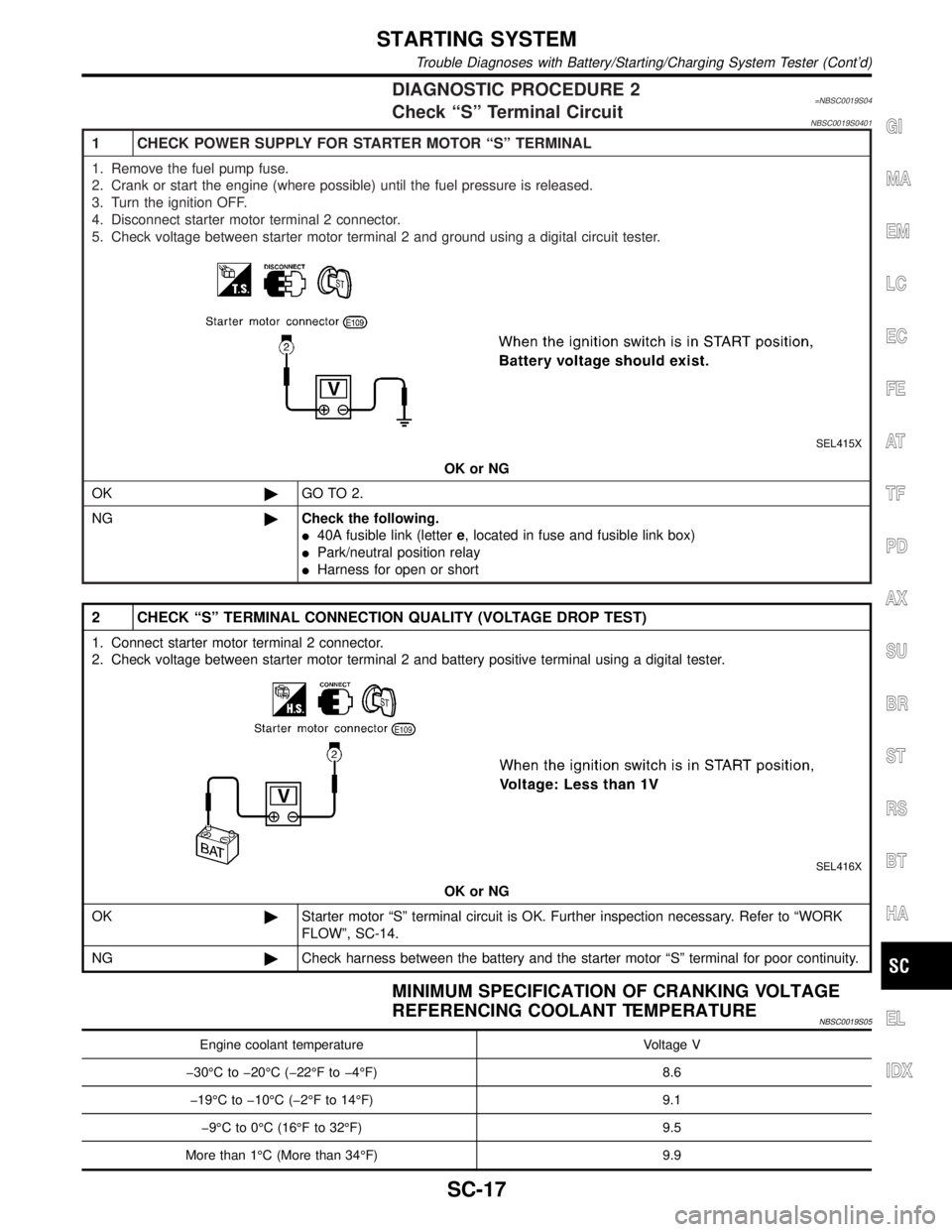
DIAGNOSTIC PROCEDURE 2=NBSC0019S04Check ªSº Terminal CircuitNBSC0019S0401
1 CHECK POWER SUPPLY FOR STARTER MOTOR ªSº TERMINAL
1. Remove the fuel pump fuse.
2. Crank or start the engine (where possible) until the fuel pressure is released.
3. Turn the ignition OFF.
4. Disconnect starter motor terminal 2 connector.
5. Check voltage between starter motor terminal 2 and ground using a digital circuit tester.
SEL415X
OK or NG
OK©GO TO 2.
NG©Check the following.
I40A fusible link (lettere, located in fuse and fusible link box)
IPark/neutral position relay
IHarness for open or short
2 CHECK ªSº TERMINAL CONNECTION QUALITY (VOLTAGE DROP TEST)
1. Connect starter motor terminal 2 connector.
2. Check voltage between starter motor terminal 2 and battery positive terminal using a digital tester.
SEL416X
OK or NG
OK©Starter motor ªSº terminal circuit is OK. Further inspection necessary. Refer to ªWORK
FLOWº, SC-14.
NG©Check harness between the battery and the starter motor ªSº terminal for poor continuity.
MINIMUM SPECIFICATION OF CRANKING VOLTAGE
REFERENCING COOLANT TEMPERATURE
NBSC0019S05
Engine coolant temperature Voltage V
þ30ÉC to þ20ÉC (þ22ÉF to þ4ÉF) 8.6
þ19ÉC to þ10ÉC (þ2ÉF to 14ÉF) 9.1
þ9ÉC to 0ÉC (16ÉF to 32ÉF) 9.5
More than 1ÉC (More than 34ÉF) 9.9
GI
MA
EM
LC
EC
FE
AT
TF
PD
AX
SU
BR
ST
RS
BT
HA
EL
IDX
STARTING SYSTEM
Trouble Diagnoses with Battery/Starting/Charging System Tester (Cont'd)
SC-17