2001 INFINITI QX4 suspension
[x] Cancel search: suspensionPage 1988 of 2395
Radiator
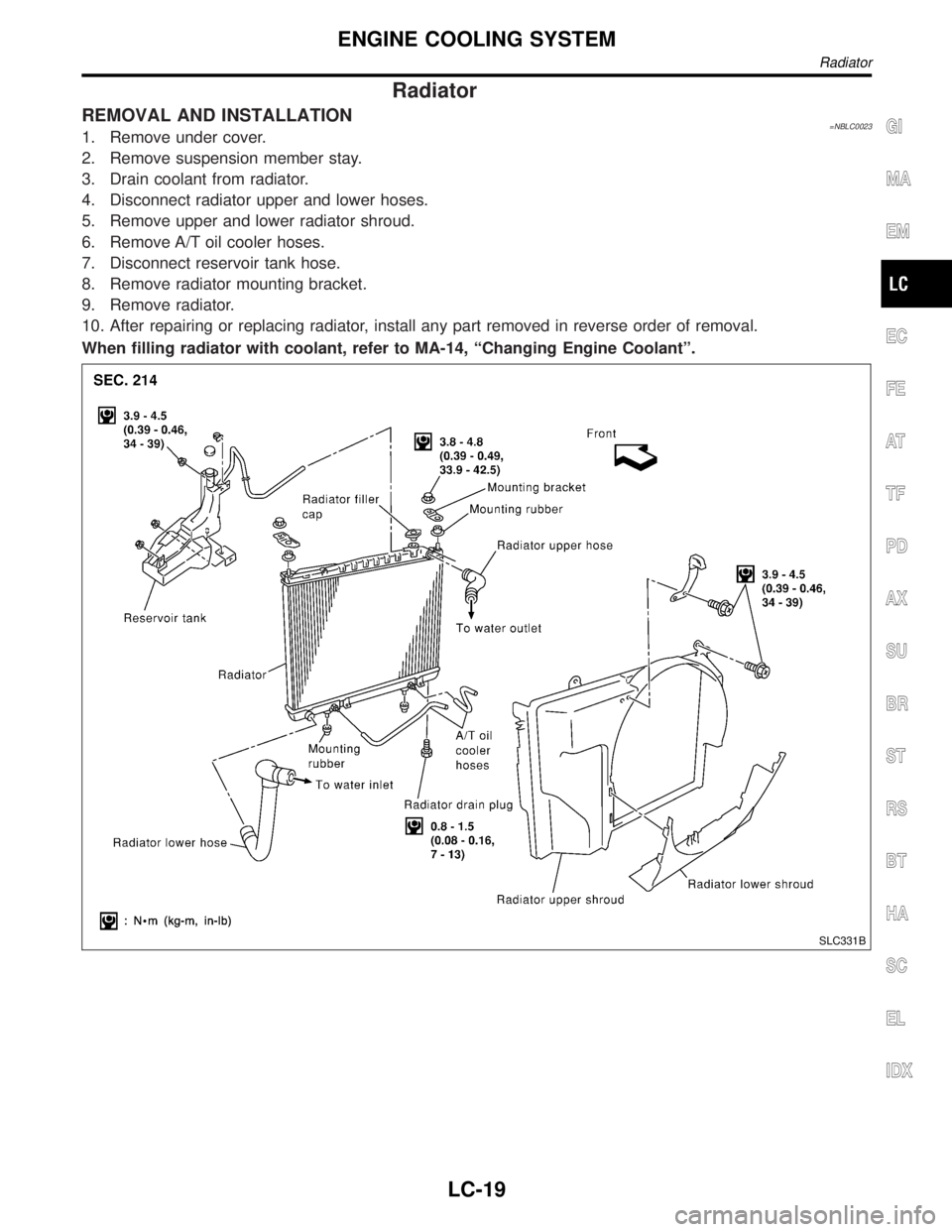
REMOVAL AND INSTALLATION=NBLC00231. Remove under cover.
2. Remove suspension member stay.
3. Drain coolant from radiator.
4. Disconnect radiator upper and lower hoses.
5. Remove upper and lower radiator shroud.
6. Remove A/T oil cooler hoses.
7. Disconnect reservoir tank hose.
8. Remove radiator mounting bracket.
9. Remove radiator.
10. After repairing or replacing radiator, install any part removed in reverse order of removal.
When filling radiator with coolant, refer to MA-14, ªChanging Engine Coolantº.
SLC331B
GI
MA
EM
EC
FE
AT
TF
PD
AX
SU
BR
ST
RS
BT
HA
SC
EL
IDX
ENGINE COOLING SYSTEM
Radiator
LC-19
Page 2003 of 2395
CHASSIS AND BODY MAINTENANCENBMA0004S0102
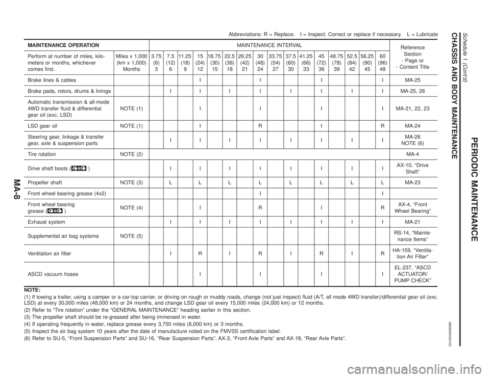
Abbreviations: R = Replace. I = Inspect. Correct or replace if necessary. L = Lubricate
MAINTENANCE OPERATIONMAINTENANCE INTERVAL
Reference
Section
- Page or
- Content Title Perform at number of miles, kilo-
meters or months, whichever
comes first.Miles x 1,000
(km x 1,000)
Months3.75
(6)
37.5
(12)
611.25
(18)
915
(24)
1218.75
(30)
1522.5
(36)
1826.25
(42)
2130
(48)
2433.75
(54)
2737.5
(60)
3041.25
(66)
3345
(72)
3648.75
(78)
3952.5
(84)
4256.25
(90)
4560
(96)
48
Brake lines & cables I I I I MA-25
Brake pads, rotors, drums & linings I IIIIIIIMA-25, 26
Automatic transmission & all-mode
4WD transfer fluid & differential
gear oil (exc. LSD)NOTE (1) I I I I MA-21, 22, 23
LSD gear oil NOTE (1) I R I R MA-24
Steering gear, linkage & transfer
gear, axle & suspension partsIIIIIIIIMA-26
NOTE (6)
Tire rotation NOTE (2)MA-4
Drive shaft boots (
) IIIIIIIIAX-10, ªDrive
Shaftº
Propeller shaft NOTE (3) L LLLLLLLMA-23
Front wheel bearing grease (4x2) I I
Front wheel bearing
grease (
)NOTE (4) I R I RAX-4, ªFront
Wheel Bearingº
Exhaust system I IIIIIIIMA-21
Supplemental air bag systems NOTE (5)RS-14, ªMainte-
nance Itemsº
Ventilation air filter I RIRIRIRHA-159, ªVentila-
tion Air Filterº
ASCD vacuum hoses I I I IEL-237, ªASCD
ACTUATOR/
PUMP CHECKº
NOTE:
(1) If towing a trailer, using a camper or a car-top carrier, or driving on rough or muddy roads, change (not just inspect) fluid (A/T, all mode 4WD transfer)/differential gear oil (exc.
LSD) at every 30,000 miles (48,000 km) or 24 months, and change LSD gear oil every 15,000 miles (24,000 km) or 12 months.
(2) Refer to ªTire rotationº under the ªGENERAL MAINTENANCEº heading earlier in this section.
(3) The propeller shaft should be re-greased after being immersed in water.
(4) If operating frequently in water, replace grease every 3,750 miles (6,000 km) or 3 months.
(5) Inspect the air bag system 10 years after the date of manufacture noted on the FMVSS certification label.
(6) Refer to SU-5, ªFront Suspension Partsº and SU-16, ªRear Suspension Partsº, AX-3, ªFront Axle Partsº and AX-18, ªRear Axle Partsº.
PERIODIC MAINTENANCE
Schedule 1 (Cont'd)
MA-8
Page 2005 of 2395
CHASSIS AND BODY MAINTENANCENBMA0004S0202
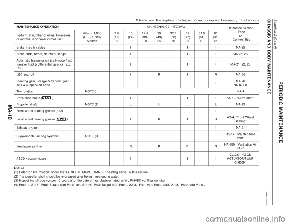
Abbreviations: R = Replace. I = Inspect. Correct or replace if necessary. L = Lubricate
MAINTENANCE OPERATIONMAINTENANCE INTERVAL
Reference Section
- Page
or
- Content Title Perform at number of miles, kilometers
or months, whichever comes first.Miles x 1,000
(km x 1,000)
Months7.5
(12)
615
(24)
1222.5
(36)
1830
(48)
2437.5
(60)
3045
(72)
3652.5
(84)
4260
(96)
48
Brake lines & cablesIIIIMA-25
Brake pads, rotors, drums & liningsIIIIMA-25, 26
Automatic transmission & all-mode 4WD
transfer fluid & differential gear oil (exc.
LSD)IIIIMA-21, 22, 23
LSD gear oilIRIRMA-24
Steering gear, linkage & transfer gear,
axle & suspension partsIIMA-26
NOTE (4)
Tire rotation NOTE (1)MA-4
Drive shaft boots (
) IIIIAX-10, ªDrive shaftº
Propeller shaft NOTE (2)LLLLMA-23
Front wheel bearing grease (4x2) I I
Front wheel bearing grease (
) IRIRAX-4, ªFront Wheel
Bearingº
Exhaust systemI I MA-21
Supplemental air bag systems NOTE (3)RS-14, ªMaintenance
Itemº
Ventilation air filterRRRRHA-159, ªVentilation Air
Filterº
ASCD vacuum hosesIIIIEL-237, ªASCD
ACTUATOR/PUMP
CHECKº
NOTE:
(1) Refer to ªTire rotationº under the ªGENERAL MAINTENANCEº heading earlier in this section.
(2) The propeller shaft should be re-greased after being immersed in water.
(3) Inspect the air bag system 10 years after the date of manufacture noted on the FMVSS certification label.
(4) Refer to SU-5, ªFront Suspension Partsº and SU-16, ªRear Suspension Partsº, AX-3, ªFront Axle Partsº and AX-18, ªRear Axle Partsº.
PERIODIC MAINTENANCE
Schedule 2 (Cont'd)
MA-10
Page 2028 of 2395
Noise, Vibration and Harshness (NVH)
Troubleshooting
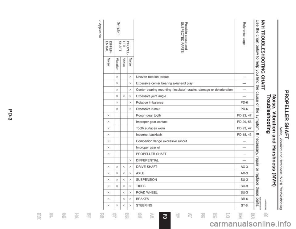
=NBPD0049NVH TROUBLESHOOTING CHARTNBPD0049S01Use the chart below to help you find the cause of the symptom. If necessary, repair or replace these parts.
Reference pageÐ
Ð
Ð
Ð
PD-6
PD-6
PD-23, 47
PD-29, 56
PD-23, 47
PD-18, 43
Ð
Ð
Ð
Ð
AX-3
AX-3
SU-3
SU-3
SU-3
BR-6
ST-6
Possible cause and
SUSPECTED PARTS
Uneven rotation torque
Excessive center bearing axial end play
Center bearing mounting (insulator) cracks, damage or deterioration
Excessive joint angle
Rotation imbalance
Excessive runout
Rough gear tooth
Improper gear contact
Tooth surfaces worn
Incorrect backlash
Companion flange excessive runout
Improper gear oil
PROPELLER SHAFT
DIFFERENTIAL
DRIVE SHAFT
AXLE
SUSPENSION
TIRES
ROAD WHEEL
BRAKES
STEERING
SymptomPROPEL-
LER
SHAFTNoise´´´´´´ ´´´´´´´´
Shake´ ´´´´´´´
Vibration´´´´´´ ´´´´ ´
DIFFER-
ENTIALNoise´´´´´´´ ´´´´´´´
´: Applicable
GI
MA
EM
LC
EC
FE
AT
TF
AX
SU
BR
ST
RS
BT
HA
SC
EL
IDX
PROPELLER SHAFT
Noise, Vibration and Harshness (NVH) Troubleshooting
PD-3
Page 2187 of 2395
NBST0043
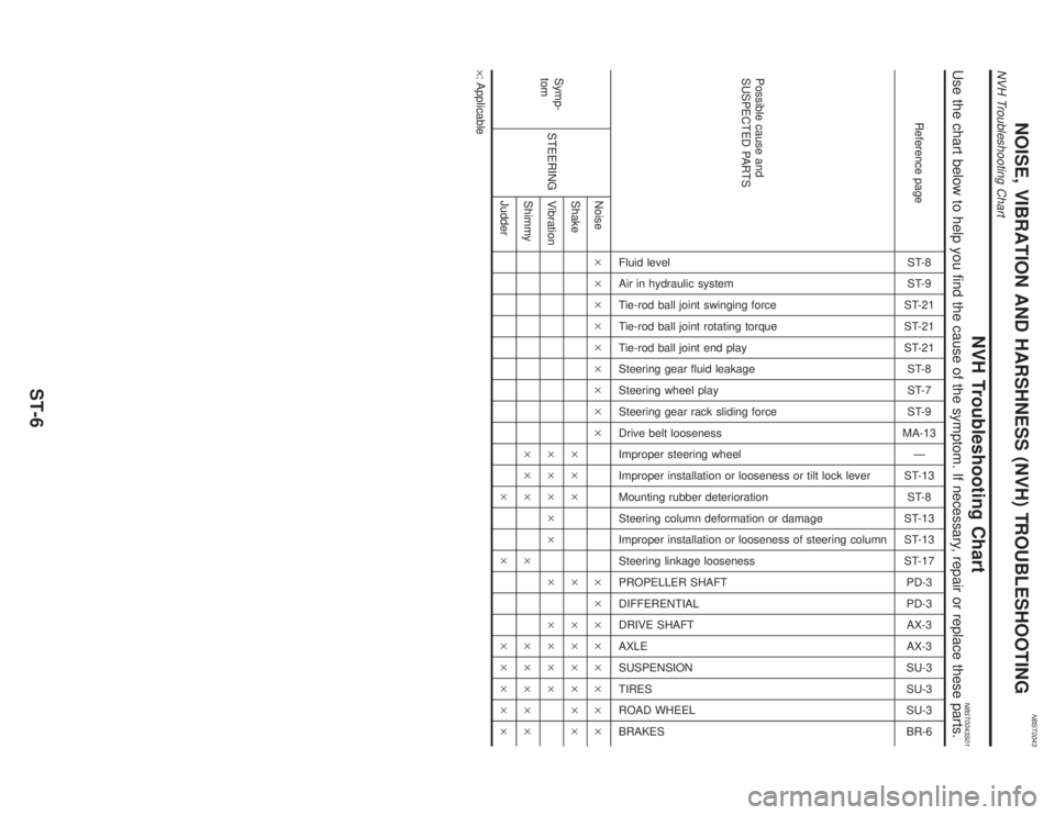
NVH Troubleshooting ChartNBST0043S01Use the chart below to help you find the cause of the symptom. If necessary, repair or replace these parts.
Reference pageST-8
ST-9
ST-21
ST-21
ST-21
ST-8
ST-7
ST-9
MA-13
Ð
ST-13
ST-8
ST-13
ST-13
ST-17
PD-3
PD-3
AX-3
AX-3
SU-3
SU-3
SU-3
BR-6
Possible cause and
SUSPECTED PARTS
Fluid level
Air in hydraulic system
Tie-rod ball joint swinging force
Tie-rod ball joint rotating torque
Tie-rod ball joint end play
Steering gear fluid leakage
Steering wheel play
Steering gear rack sliding force
Drive belt looseness
Improper steering wheel
Improper installation or looseness or tilt lock lever
Mounting rubber deterioration
Steering column deformation or damage
Improper installation or looseness of steering column
Steering linkage looseness
PROPELLER SHAFT
DIFFERENTIAL
DRIVE SHAFT
AXLE
SUSPENSION
TIRES
ROAD WHEEL
BRAKES
Symp-
tomSTEERINGNoise´´´´´´´´´ ´´´´´´´´
Shake´´´ ´ ´´´´´´
Vibration´´´´´ ´ ´´´´
Shimmy´´´ ´ ´´´´´
Judder´ ´ ´´´´´
´: Applicable
NOISE, VIBRATION AND HARSHNESS (NVH) TROUBLESHOOTING
NVH Troubleshooting Chart
ST-6
Page 2188 of 2395
SST489B
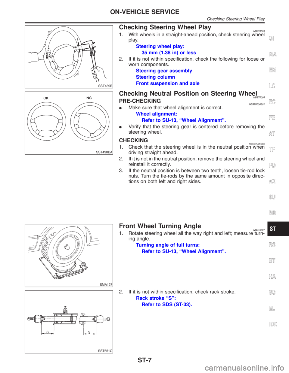
Checking Steering Wheel PlayNBST00051. With wheels in a straight-ahead position, check steering wheel
play.
Steering wheel play:
35 mm (1.38 in) or less
2. If it is not within specification, check the following for loose or
worn components.
Steering gear assembly
Steering column
Front suspension and axle
SST490BA
Checking Neutral Position on Steering WheelNBST0006PRE-CHECKINGNBST0006S01IMake sure that wheel alignment is correct.
Wheel alignment:
Refer to SU-13, ªWheel Alignmentº.
IVerify that the steering gear is centered before removing the
steering wheel.
CHECKINGNBST0006S021. Check that the steering wheel is in the neutral position when
driving straight ahead.
2. If it is not in the neutral position, remove the steering wheel and
reinstall it correctly.
3. If the neutral position is between two teeth, loosen tie-rod lock
nuts. Turn the tie-rods by the same amount in opposite direc-
tions on both left and right sides.
SMA127
Front Wheel Turning AngleNBST00071. Rotate steering wheel all the way right and left; measure turn-
ing angle.
Turning angle of full turns:
Refer to SU-13, ªWheel Alignmentº.
SST651C
2. If it is not within specification, check rack stroke.
Rack stroke ªSº:
Refer to SDS (ST-33).
GI
MA
EM
LC
EC
FE
AT
TF
PD
AX
SU
BR
RS
BT
HA
SC
EL
IDX
ON-VEHICLE SERVICE
Checking Steering Wheel Play
ST-7
Page 2216 of 2395
FRONT & REAR SUSPENSION
SECTION
SU
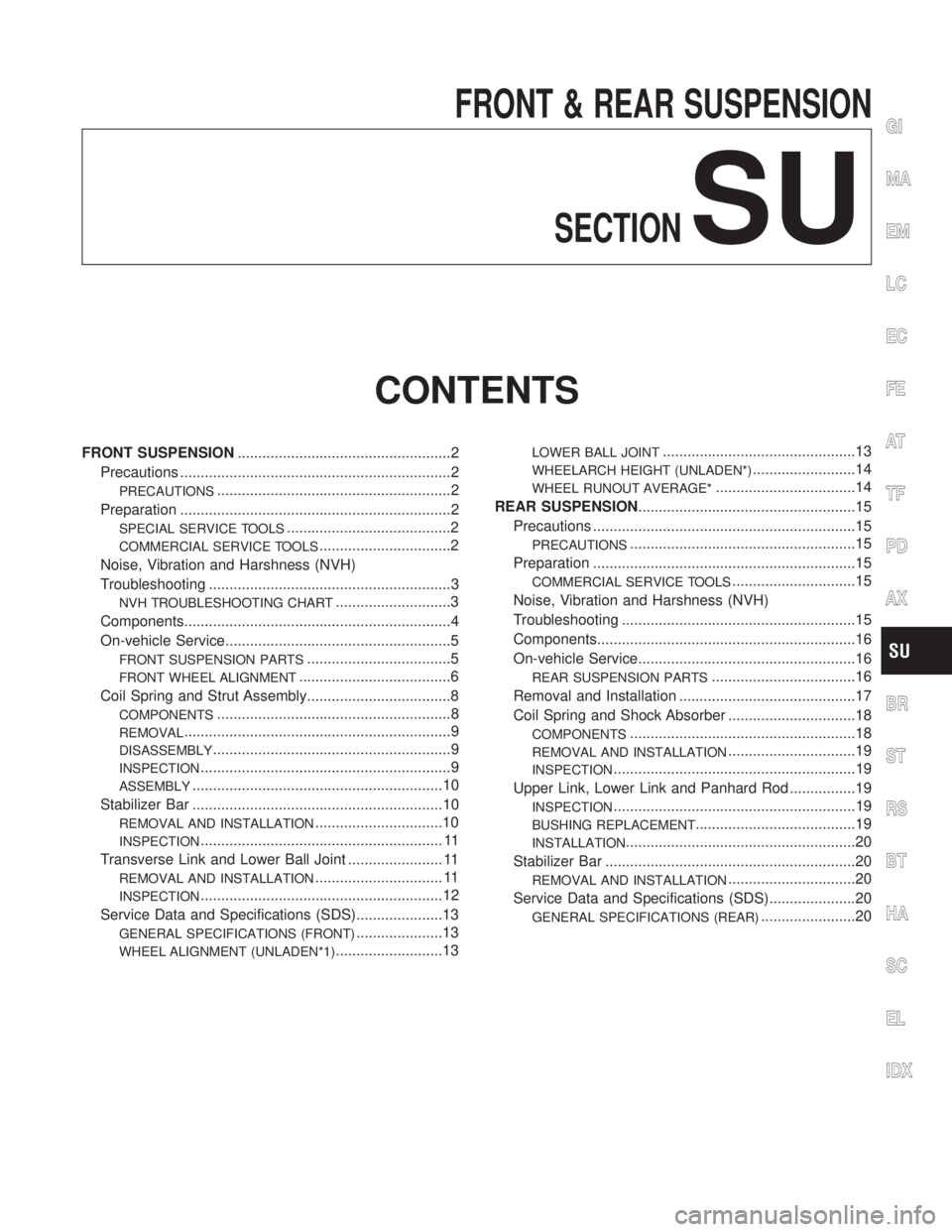
CONTENTS
FRONT SUSPENSION....................................................2
Precautions ..................................................................2
PRECAUTIONS.........................................................2
Preparation ..................................................................2
SPECIAL SERVICE TOOLS........................................2
COMMERCIAL SERVICE TOOLS................................2
Noise, Vibration and Harshness (NVH)
Troubleshooting ...........................................................3
NVH TROUBLESHOOTING CHART............................3
Components.................................................................4
On-vehicle Service.......................................................5
FRONT SUSPENSION PARTS...................................5
FRONT WHEEL ALIGNMENT.....................................6
Coil Spring and Strut Assembly...................................8
COMPONENTS.........................................................8
REMOVAL.................................................................9
DISASSEMBLY..........................................................9
INSPECTION.............................................................9
ASSEMBLY.............................................................10
Stabilizer Bar .............................................................10
REMOVAL AND INSTALLATION...............................10
INSPECTION........................................................... 11
Transverse Link and Lower Ball Joint ....................... 11
REMOVAL AND INSTALLATION............................... 11
INSPECTION...........................................................12
Service Data and Specifications (SDS).....................13
GENERAL SPECIFICATIONS (FRONT).....................13
WHEEL ALIGNMENT (UNLADEN*1)..........................13
LOWER BALL JOINT...............................................13
WHEELARCH HEIGHT (UNLADEN*).........................14
WHEEL RUNOUT AVERAGE*..................................14
REAR SUSPENSION.....................................................15
Precautions ................................................................15
PRECAUTIONS.......................................................15
Preparation ................................................................15
COMMERCIAL SERVICE TOOLS..............................15
Noise, Vibration and Harshness (NVH)
Troubleshooting .........................................................15
Components...............................................................16
On-vehicle Service.....................................................16
REAR SUSPENSION PARTS...................................16
Removal and Installation ...........................................17
Coil Spring and Shock Absorber ...............................18
COMPONENTS.......................................................18
REMOVAL AND INSTALLATION...............................19
INSPECTION...........................................................19
Upper Link, Lower Link and Panhard Rod ................19
INSPECTION...........................................................19
BUSHING REPLACEMENT.......................................19
INSTALLATION........................................................20
Stabilizer Bar .............................................................20
REMOVAL AND INSTALLATION...............................20
Service Data and Specifications (SDS).....................20
GENERAL SPECIFICATIONS (REAR).......................20
GI
MA
EM
LC
EC
FE
AT
TF
PD
AX
BR
ST
RS
BT
HA
SC
EL
IDX
Page 2217 of 2395
SBR686C
Precautions
PRECAUTIONSNBSU0001IWhen installing rubber parts, final tightening must be car-
ried out under unladen condition* with tires on ground.
*Fuel, radiator coolant and engine oil full. Spare tire, jack,
hand tools and mats in designated positions.
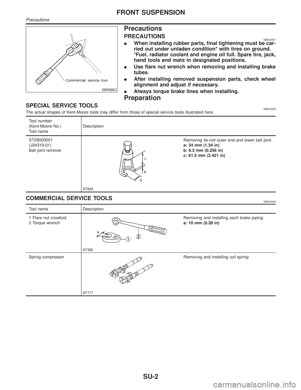
IUse flare nut wrench when removing and installing brake
tubes.
IAfter installing removed suspension parts, check wheel
alignment and adjust if necessary.
IAlways torque brake lines when installing.
Preparation
SPECIAL SERVICE TOOLSNBSU0002The actual shapes of Kent-Moore tools may differ from those of special service tools illustrated here.
Tool number
(Kent-Moore No.)
Tool nameDescription
ST29020001
(J24319-01)
Ball joint remover
NT694
Removing tie-rod outer end and lower ball joint
a: 34 mm (1.34 in)
b: 6.5 mm (0.256 in)
c: 61.5 mm (2.421 in)
COMMERCIAL SERVICE TOOLSNBSU0003
Tool name Description
1 Flare nut crowfoot
2 Torque wrench
NT360
Removing and installing each brake piping
a: 10 mm (0.39 in)
Spring compressor
NT717
Removing and installing coil spring
FRONT SUSPENSION
Precautions
SU-2