2001 INFINITI QX4 power seat
[x] Cancel search: power seatPage 1392 of 2395
![INFINITI QX4 2001 Factory Service Manual DIAGNOSTIC PROCEDURE 4=NBEL0214S07[Lifting encoder (front) check]
1 CHECK LIFTING ENCODER (FRONT) OUTPUT SIGNAL
Measure voltage between seat control unit LH terminal 19 and ground with CONSULT-II or o INFINITI QX4 2001 Factory Service Manual DIAGNOSTIC PROCEDURE 4=NBEL0214S07[Lifting encoder (front) check]
1 CHECK LIFTING ENCODER (FRONT) OUTPUT SIGNAL
Measure voltage between seat control unit LH terminal 19 and ground with CONSULT-II or o](/manual-img/42/57027/w960_57027-1391.png)
DIAGNOSTIC PROCEDURE 4=NBEL0214S07[Lifting encoder (front) check]
1 CHECK LIFTING ENCODER (FRONT) OUTPUT SIGNAL
Measure voltage between seat control unit LH terminal 19 and ground with CONSULT-II or oscilloscope when power seat
lifting (front) is operated.
SEL611W
OK or NG
OK©Lifting encoder (front) is OK.
NG©GO TO 2.
2 CHECK LIFTING ENCODER (FRONT) INPUT SIGNAL
Check voltage between seat control unit LH terminal 17 and ground.
SEL612W
OK or NG
OK©GO TO 3.
NG©Replace seat control unit LH.
GI
MA
EM
LC
EC
FE
AT
TF
PD
AX
SU
BR
ST
RS
BT
HA
SC
IDX
AUTOMATIC DRIVE POSITIONER
Trouble Diagnoses (Cont'd)
EL-207
Page 1394 of 2395
![INFINITI QX4 2001 Factory Service Manual DIAGNOSTIC PROCEDURE 5=NBEL0214S08[Lifting encoder (rear) check]
1 CHECK LIFTING ENCODER (REAR) OUTPUT SIGNAL
Measure voltage between seat control unit LH terminal 30 and ground with CONSULT-II or osc INFINITI QX4 2001 Factory Service Manual DIAGNOSTIC PROCEDURE 5=NBEL0214S08[Lifting encoder (rear) check]
1 CHECK LIFTING ENCODER (REAR) OUTPUT SIGNAL
Measure voltage between seat control unit LH terminal 30 and ground with CONSULT-II or osc](/manual-img/42/57027/w960_57027-1393.png)
DIAGNOSTIC PROCEDURE 5=NBEL0214S08[Lifting encoder (rear) check]
1 CHECK LIFTING ENCODER (REAR) OUTPUT SIGNAL
Measure voltage between seat control unit LH terminal 30 and ground with CONSULT-II or oscilloscope when power seat
lifting (rear) is operated.
SEL615W
OK or NG
OK©Lifting encoder (rear) is OK.
NG©GO TO 2.
2 CHECK LIFTING ENCODER (REAR) INPUT SIGNAL
Check voltage between seat control unit LH terminal 17 and ground.
SEL616W
OK or NG
OK©GO TO 3.
NG©Replace seat control unit LH.
GI
MA
EM
LC
EC
FE
AT
TF
PD
AX
SU
BR
ST
RS
BT
HA
SC
IDX
AUTOMATIC DRIVE POSITIONER
Trouble Diagnoses (Cont'd)
EL-209
Page 1400 of 2395

DIAGNOSTIC PROCEDURE 10=NBEL0214S13(Power seat switch check)
1 CHECK POWER SEAT SWITCH
1. Disconnect power seat switch LH connector.
2. Check continuity between power seat switch terminals.
SEL569X
OK or NG
OK©Check the following.
IGround circuit for power seat switch
IHarness for open or short between seat control unit LH and power seat switch
NG©Replace power seat switch.
GI
MA
EM
LC
EC
FE
AT
TF
PD
AX
SU
BR
ST
RS
BT
HA
SC
IDX
AUTOMATIC DRIVE POSITIONER
Trouble Diagnoses (Cont'd)
EL-215
Page 1405 of 2395

DIAGNOSTIC PROCEDURE 13=NBEL0214S16(Seat memory switch check)
1 CHECK SEAT MEMORY SWITCH
1. Disconnect seat memory switch connector.
2. Check continuity between seat memory switch terminals.
SEL634WA
OK or NG
OK©Check the following.
IGround circuit for seat memory switch
IHarness for open or short between seat control unit LH and seat memory switch
NG©Replace seat memory switch.
DIAGNOSTIC PROCEDURE 14NBEL0214S17(Memory indicator check)
1 CHECK INDICATOR LAMP
Check indicator lamp illumination.
OK or NG
OK©GO TO 2.
NG©Replace seat memory switch (indicator lamp).
2 CHECK POWER SUPPLY CIRCUIT FOR INDICATOR LAMP
1. Disconnect seat memory switch connector.
2. Check voltage between seat memory switch terminal and ground.
SEL635WA
OK or NG
OK©Check harness for open or short between seat control unit LH and seat memory switch
NG©Check the following.
I7.5A fuse [No. 24 located in the fuse block (J/B)]
IHarness for open or short between fuse and indicator lamp
AUTOMATIC DRIVE POSITIONER
Trouble Diagnoses (Cont'd)
EL-220
Page 1504 of 2395

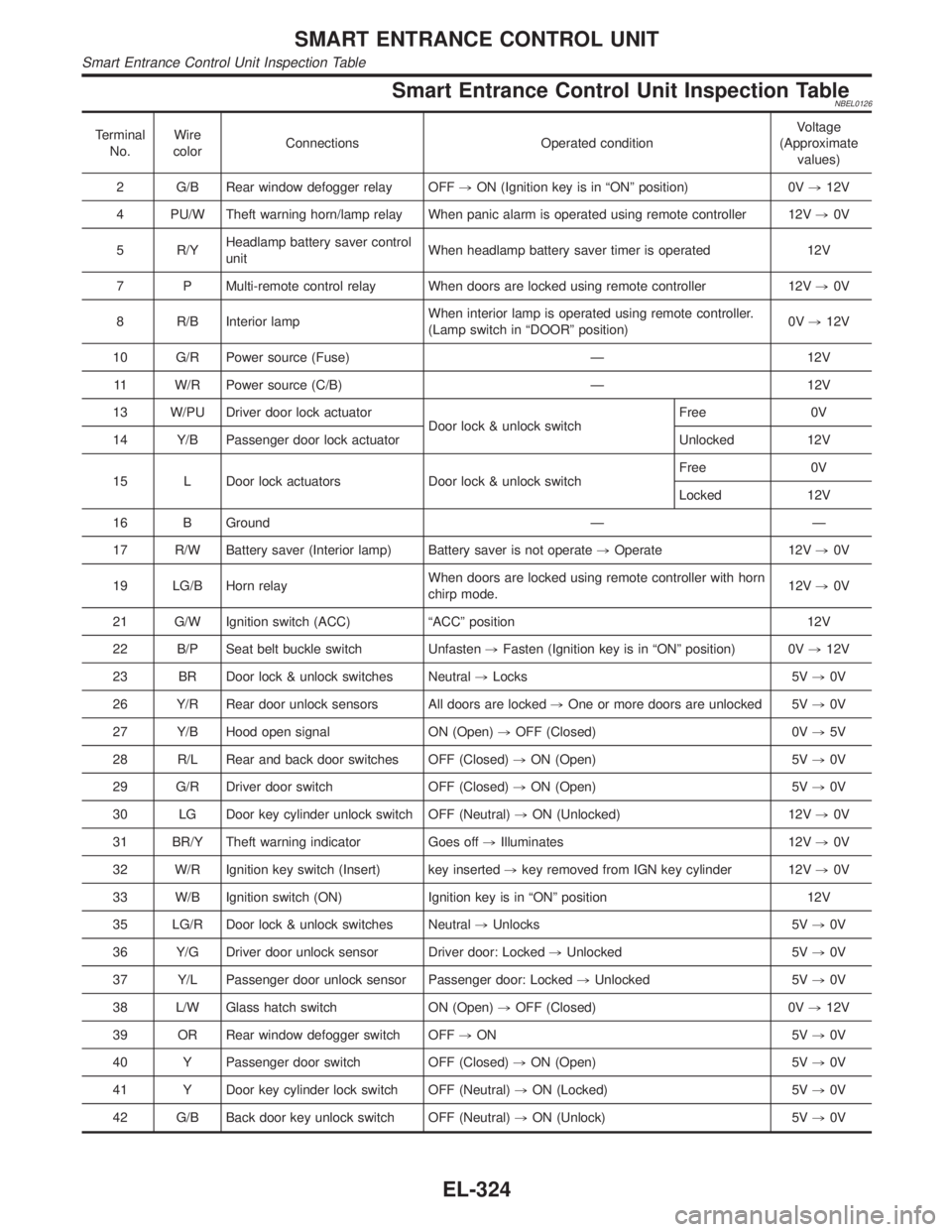
DescriptionNBEL0124The following systems are controlled by the smart entrance control unit.
IWarning chime
IRear window defogger and door mirror defogger timer
IPower door lock
IMulti-remote control system
ITheft warning system
IInterior lamp timer
IElectric sunroof and power window timer
IHeadlamp battery saver
IBattery saver
For detailed description and wiring diagrams, refer to the relevant pages for the each system.
The smart entrance control unit receives data from the switches and sensors to control their corresponding
system relays and actuators.
INPUT/OUTPUTNBEL0124S01
System Input Output
Power door lockDoor lock and unlock switch LH and RH
Key switch (Insert)
Door switches
Door key cylinder switchesDoor lock actuator
Multi-remote controlKey switch (Insert)
Ignition switch (ACC)
Door switches
Front door unlock sensor LH
Door lock and unlock switch LH
Remote controller signalHorn relay
Headlamp relay (LH and RH)
Interior lamp
Multi-remote control relay
Door lock actuator
Warning chimeKey switch (Insert)
Ignition switch (ON)
Lighting switch (1st)
Seat belt switch
Front door switch LHWarning chime (located in smart entrance
control unit)
Rear window defogger and
door mirror defogger timerIgnition switch (ON)
Rear window defogger switchRear window defogger relay
Theft warningIgnition switch (ACC, ON)
Door switches
Hood switch
Glass hatch switch
Door key cylinder switches (lock/unlock)
Door unlock sensoresHorn relay
Headlamp relay (LH and RH)
Security indicator
Interior lamp timerDoor switches
Front door unlock sensor LH
Ignition switch (ON)
Key switch (Insert)Interior lamp
Electric sunroof and power
window timerFront door switches
Ignition switch (ON)Power window relay
Headlamp battery saver timerFront door switches
Ignition switch (ON)Headlamp battery saver control unit
Battery saverIgnition switch (ON)
Door switches
Driver's door unlock sensor
Key switch (Insert)Interior lamp
Luggage room lamp
Spot lamp
Vanity mirror illumination lamp
GI
MA
EM
LC
EC
FE
AT
TF
PD
AX
SU
BR
ST
RS
BT
HA
SC
IDX
SMART ENTRANCE CONTROL UNIT
Description
EL-319
Page 1509 of 2395

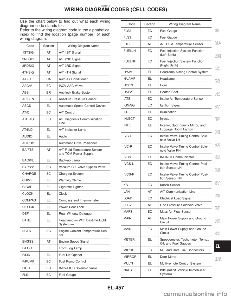
Smart Entrance Control Unit Inspection TableNBEL0126
Terminal
No.Wire
colorConnections Operated conditionVoltage
(Approximate
values)
2 G/B Rear window defogger relay OFF,ON (Ignition key is in ªONº position) 0V,12V
4 PU/W Theft warning horn/lamp relay When panic alarm is operated using remote controller 12V,0V
5 R/YHeadlamp battery saver control
unitWhen headlamp battery saver timer is operated 12V
7 P Multi-remote control relay When doors are locked using remote controller 12V,0V
8 R/B Interior lampWhen interior lamp is operated using remote controller.
(Lamp switch in ªDOORº position)0V,12V
10 G/R Power source (Fuse) Ð 12V
11 W/R Power source (C/B) Ð 12V
13 W/PU Driver door lock actuator
Door lock & unlock switchFree 0V
14 Y/B Passenger door lock actuator Unlocked 12V
15 L Door lock actuators Door lock & unlock switchFree 0V
Locked 12V
16 B Ground Ð Ð
17 R/W Battery saver (Interior lamp) Battery saver is not operate,Operate 12V,0V
19 LG/B Horn relayWhen doors are locked using remote controller with horn
chirp mode.12V,0V
21 G/W Ignition switch (ACC) ªACCº position 12V
22 B/P Seat belt buckle switch Unfasten,Fasten (Ignition key is in ªONº position) 0V,12V
23 BR Door lock & unlock switches Neutral,Locks 5V,0V
26 Y/R Rear door unlock sensors All doors are locked,One or more doors are unlocked 5V,0V
27 Y/B Hood open signal ON (Open),OFF (Closed) 0V,5V
28 R/L Rear and back door switches OFF (Closed),ON (Open) 5V,0V
29 G/R Driver door switch OFF (Closed),ON (Open) 5V,0V
30 LG Door key cylinder unlock switch OFF (Neutral),ON (Unlocked) 12V,0V
31 BR/Y Theft warning indicator Goes off,Illuminates 12V,0V
32 W/R Ignition key switch (Insert) key inserted,key removed from IGN key cylinder 12V,0V
33 W/B Ignition switch (ON) Ignition key is in ªONº position 12V
35 LG/R Door lock & unlock switches Neutral,Unlocks 5V,0V
36 Y/G Driver door unlock sensor Driver door: Locked,Unlocked 5V,0V
37 Y/L Passenger door unlock sensor Passenger door: Locked,Unlocked 5V,0V
38 L/W Glass hatch switch ON (Open),OFF (Closed) 0V,12V
39 OR Rear window defogger switch OFF,ON 5V,0V
40 Y Passenger door switch OFF (Closed),ON (Open) 5V,0V
41 Y Door key cylinder lock switch OFF (Neutral),ON (Locked) 5V,0V
42 G/B Back door key unlock switch OFF (Neutral),ON (Unlock) 5V,0V
SMART ENTRANCE CONTROL UNIT
Smart Entrance Control Unit Inspection Table
EL-324
Page 1642 of 2395

NBEL0145
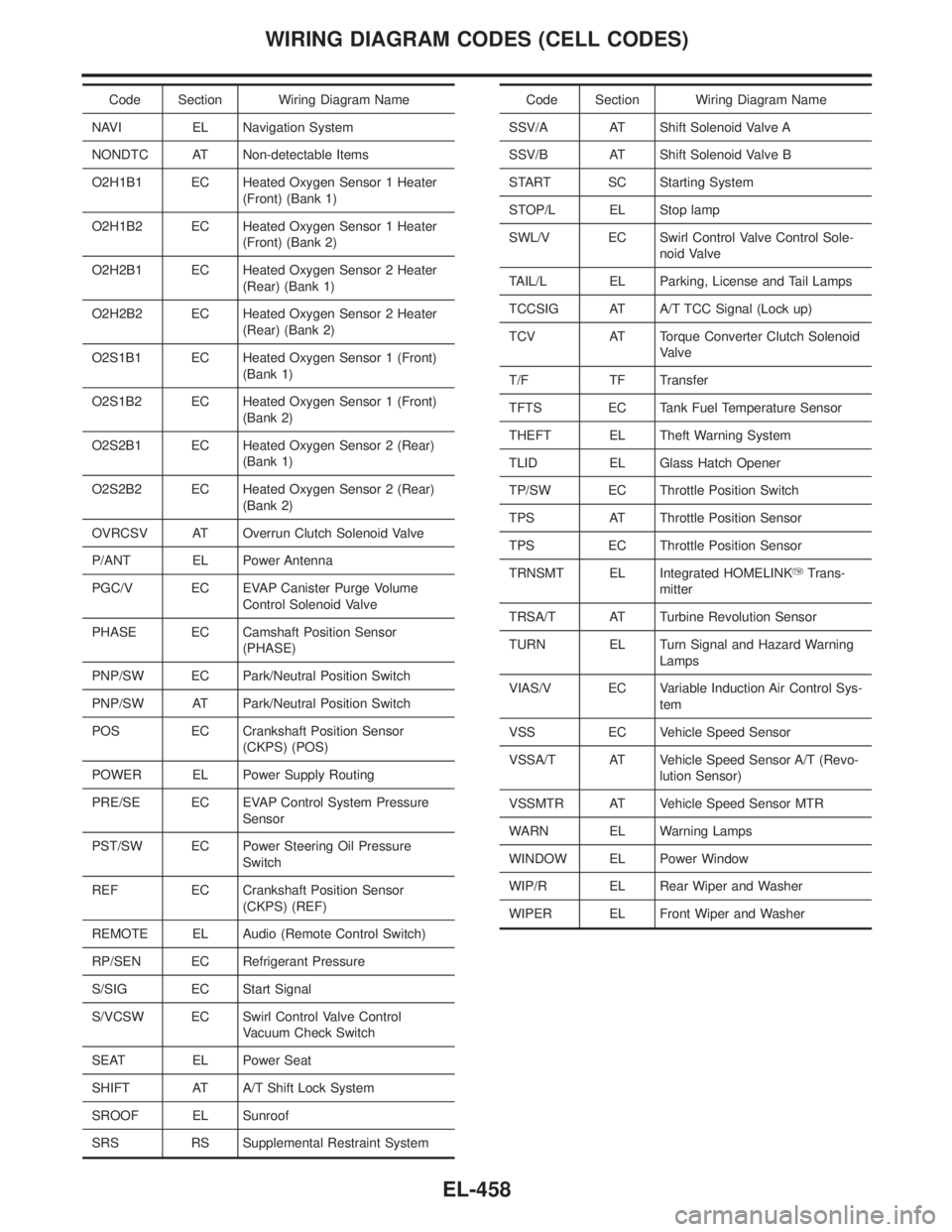
Use the chart below to find out what each wiring
diagram code stands for.
Refer to the wiring diagram code in the alphabetical
index to find the location (page number) of each
wiring diagram.
Code Section Wiring Diagram Name
1STSIG AT A/T 1ST Signal
2NDSIG AT A/T 2ND Signal
3RDSIG AT A/T 3RD Signal
4THSIG AT A/T 4TH Signal
A/C, A HA Auto Air Conditioner
AAC/V EC IACV-AAC Valve
ABS BR Anti-lock Brake System
AP/SEN EC Absolute Pressure Sensor
ASCD EL Automatic Speed Control Device
AT/C EC A/T Control
ATDIAG EC A/T Diagnosis Communication
Line
AT/IND EL A/T Indicator Lamp
AUDIO EL Audio
AUT/DP EL Automatic Drive Positioner
BA/FTS AT A/T Fluid Temperature Sensor
and TCM Power Supply
BACK/L EL Back-up Lamp
BYPS/V EC Vacuum Cut Valve Bypass Valve
CHARGE SC Charging System
CHIME EL Warning Chime
CIGAR EL Cigarette Lighter
CLOCK EL Clock
COMPAS EL Compass and Thermometer
D/LOCK EL Power Door Lock
DEF EL Rear Window Defogger
DTRL EL Headlamp Ð With Daytime Light
System Ð
ECTS EC Engine Coolant Temperature Sen-
sor
ENGSS AT Engine Speed Signal
F/FOG EL Front Fog Lamp
F/LID EL Fuel Lid Opener
F/PUMP EC Fuel Pump Control
FICD EC IACV-FICD Solenoid Valve
FLS1 EC Fuel Gauge
Code Section Wiring Diagram Name
FLS2 EC Fuel Gauge
FLS3 EC Fuel Gauge
FTS AT A/T Fluid Temperature Sensor
FUELLH EC Fuel Injection System Function
(Left Bank)
FUELRH EC Fuel Injection System Function
(Right Bank)
H/AIM EL Headlamp Aiming Control System
H/LAMP EL Headlamp
HORN EL Horn
HSEAT EL Heated Seat
IATS EC Intake Air Temperature Sensor
IGN/SG EC Ignition Signal
ILL EL Illumination
INJECT EC Injector
INT/L EL Interior, Spot, Vanity Mirror, and
Luggage Room Lamps
IVC-L EC Intake Valve Timing Control Sole-
noid Valve LH
IVC-R EC Intake Valve Timing Control Sole-
noid Valve RH
IVCS EL INFINITI Communicator
IVCS-L EC Intake Valve Timing Control Posi-
tion Sensor LH
IVCS-R EC Intake Valve Timing Control Posi-
tion Sensor RH
KS EC Knock Sensor
LAN AT A/T Communication Line
LOAD EC Electrical Load Signal
LPSV AT Line Pressure Solenoid Valve
MAFS EC Mass Air Flow Sensor
MAIN AT Main Power Supply and Ground
Circuit
MAIN EC Main Power Supply and Ground
Circuit
METER EL Speedometer, Tachometer, Temp.,
Oil, and Fuel Gauges
MIL/DL EC MIL and Data Link Connectors
MIRROR EL Door Mirror
MULTI EL Multi-remote Control System
NATS EL IVIS (Infiniti Vehicle Immobiliser
System)
GI
MA
EM
LC
EC
FE
AT
TF
PD
AX
SU
BR
ST
RS
BT
HA
SC
IDX
WIRING DIAGRAM CODES (CELL CODES)
EL-457
Page 1643 of 2395

Code Section Wiring Diagram Name
NAVI EL Navigation System
NONDTC AT Non-detectable Items
O2H1B1 EC Heated Oxygen Sensor 1 Heater
(Front) (Bank 1)
O2H1B2 EC Heated Oxygen Sensor 1 Heater
(Front) (Bank 2)
O2H2B1 EC Heated Oxygen Sensor 2 Heater
(Rear) (Bank 1)
O2H2B2 EC Heated Oxygen Sensor 2 Heater
(Rear) (Bank 2)
O2S1B1 EC Heated Oxygen Sensor 1 (Front)
(Bank 1)
O2S1B2 EC Heated Oxygen Sensor 1 (Front)
(Bank 2)
O2S2B1 EC Heated Oxygen Sensor 2 (Rear)
(Bank 1)
O2S2B2 EC Heated Oxygen Sensor 2 (Rear)
(Bank 2)
OVRCSV AT Overrun Clutch Solenoid Valve
P/ANT EL Power Antenna
PGC/V EC EVAP Canister Purge Volume
Control Solenoid Valve
PHASE EC Camshaft Position Sensor
(PHASE)
PNP/SW EC Park/Neutral Position Switch
PNP/SW AT Park/Neutral Position Switch
POS EC Crankshaft Position Sensor
(CKPS) (POS)
POWER EL Power Supply Routing
PRE/SE EC EVAP Control System Pressure
Sensor
PST/SW EC Power Steering Oil Pressure
Switch
REF EC Crankshaft Position Sensor
(CKPS) (REF)
REMOTE EL Audio (Remote Control Switch)
RP/SEN EC Refrigerant Pressure
S/SIG EC Start Signal
S/VCSW EC Swirl Control Valve Control
Vacuum Check Switch
SEAT EL Power Seat
SHIFT AT A/T Shift Lock System
SROOF EL Sunroof
SRS RS Supplemental Restraint SystemCode Section Wiring Diagram Name
SSV/A AT Shift Solenoid Valve A
SSV/B AT Shift Solenoid Valve B
START SC Starting System
STOP/L EL Stop lamp
SWL/V EC Swirl Control Valve Control Sole-
noid Valve
TAIL/L EL Parking, License and Tail Lamps
TCCSIG AT A/T TCC Signal (Lock up)
TCV AT Torque Converter Clutch Solenoid
Valve
T/F TF Transfer
TFTS EC Tank Fuel Temperature Sensor
THEFT EL Theft Warning System
TLID EL Glass Hatch Opener
TP/SW EC Throttle Position Switch
TPS AT Throttle Position Sensor
TPS EC Throttle Position Sensor
TRNSMT EL Integrated HOMELINKYTrans-
mitter
TRSA/T AT Turbine Revolution Sensor
TURN EL Turn Signal and Hazard Warning
Lamps
VIAS/V EC Variable Induction Air Control Sys-
tem
VSS EC Vehicle Speed Sensor
VSSA/T AT Vehicle Speed Sensor A/T (Revo-
lution Sensor)
VSSMTR AT Vehicle Speed Sensor MTR
WARN EL Warning Lamps
WINDOW EL Power Window
WIP/R EL Rear Wiper and Washer
WIPER EL Front Wiper and Washer
WIRING DIAGRAM CODES (CELL CODES)
EL-458