2001 INFINITI QX4 length
[x] Cancel search: lengthPage 408 of 2395

SBR002A
SBR365AA
On-vehicle ServiceNBBR0024OPERATING CHECKNBBR0024S011. Depress brake pedal several times with engine off. After
exhausting vacuum, make sure there is no change in pedal
stroke.
2. Depress brake pedal, then start engine. If pedal goes down
slightly, operation is normal.
AIRTIGHT CHECKNBBR0024S021. Start engine, and stop it after one or two minutes. Depress
brake pedal several times slowly. Booster is airtight if pedal
stroke is less each time.
2. Depress brake pedal while engine is running, and stop engine
with pedal depressed. The pedal stroke should not change
after holding pedal down for30 seconds.
SBR368DA
RemovalNBBR0025CAUTION:
IBe careful not to splash brake fluid on painted areas; it
may cause paint damage. If brake fluid is splashed on
painted areas, wash it away with water immediately.
IBe careful not to deform or bend brake pipes, during
removal of booster.
SBR208E
InspectionNBBR0026OUTPUT ROD LENGTH CHECKNBBR0026S011. Apply vacuum of þ66.7 kPa (þ500 mmHg, þ19.69 inHg) to
brake booster with a hand vacuum pump.
2. Add preload of 19.6 N (2.0 kg, 4.4 lb) to output rod.
3. Check output rod length.
Specified length:
10.275 - 10.525 mm (0.4045 - 0.4144 in)
GI
MA
EM
LC
EC
FE
AT
TF
PD
AX
SU
ST
RS
BT
HA
SC
EL
IDX
BRAKE BOOSTER
On-vehicle Service
BR-19
Page 472 of 2395

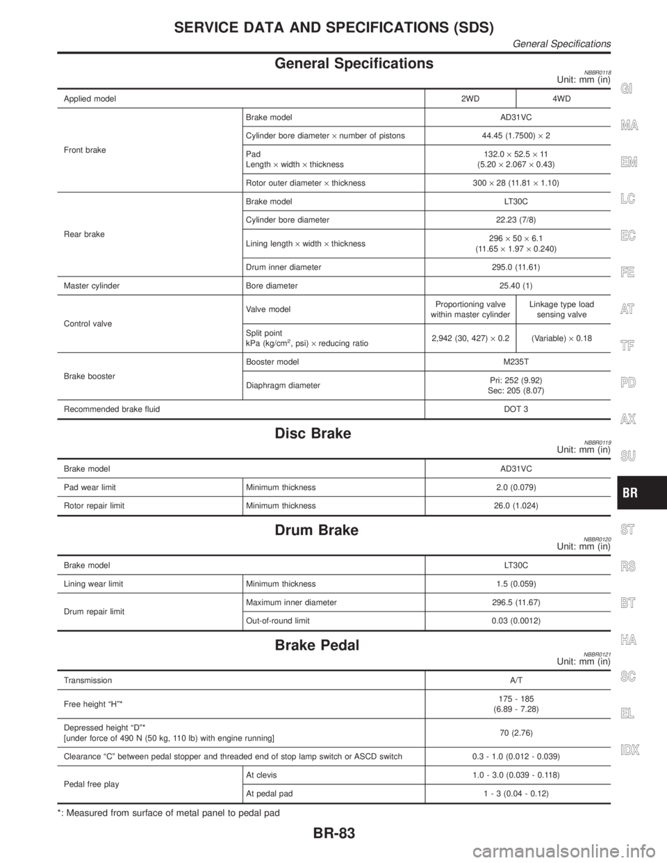
General SpecificationsNBBR0118Unit: mm (in)
Applied model2WD 4WD
Front brakeBrake model AD31VC
Cylinder bore diameter´number of pistons 44.45 (1.7500)´2
Pad
Length´width´thickness132.0´52.5´11
(5.20´2.067´0.43)
Rotor outer diameter´thickness 300´28 (11.81´1.10)
Rear brakeBrake model LT30C
Cylinder bore diameter 22.23 (7/8)
Lining length´width´thickness296´50´6.1
(11.65´1.97´0.240)
Drum inner diameter 295.0 (11.61)
Master cylinder Bore diameter 25.40 (1)
Control valveValve modelProportioning valve
within master cylinderLinkage type load
sensing valve
Split point
kPa (kg/cm
2, psi)´reducing ratio2,942 (30, 427)´0.2 (Variable)´0.18
Brake boosterBooster model M235T
Diaphragm diameterPri: 252 (9.92)
Sec: 205 (8.07)
Recommended brake fluidDOT 3
Disc BrakeNBBR0119Unit: mm (in)
Brake modelAD31VC
Pad wear limit Minimum thickness 2.0 (0.079)
Rotor repair limit Minimum thickness 26.0 (1.024)
Drum BrakeNBBR0120Unit: mm (in)
Brake modelLT30C
Lining wear limit Minimum thickness 1.5 (0.059)
Drum repair limitMaximum inner diameter 296.5 (11.67)
Out-of-round limit 0.03 (0.0012)
Brake PedalNBBR0121Unit: mm (in)
TransmissionA/T
Free height ªHº*175 - 185
(6.89 - 7.28)
Depressed height ªDº*
[under force of 490 N (50 kg, 110 lb) with engine running]70 (2.76)
Clearance ªCº between pedal stopper and threaded end of stop lamp switch or ASCD switch 0.3 - 1.0 (0.012 - 0.039)
Pedal free playAt clevis 1.0 - 3.0 (0.039 - 0.118)
At pedal pad1 - 3 (0.04 - 0.12)
*: Measured from surface of metal panel to pedal pad
GI
MA
EM
LC
EC
FE
AT
TF
PD
AX
SU
ST
RS
BT
HA
SC
EL
IDX
SERVICE DATA AND SPECIFICATIONS (SDS)
General Specifications
BR-83
Page 518 of 2395

AdjustmentNBBT0016Install motor & limit SW assembly and sunroof rail assembly in the following sequence:
1. Arrange equal lengths of link and wire assemblies on both sides of sunroof opening.
2. Connect sunroof connector to sunroof switch and positive (+) power supply.
3. Set lid assembly to fully closed position
by operating OPEN switch and TILT switch.
4. Fit outer side of lid assembly to the surface of roof on body outer panel.
5. Remove motor, and keep OPEN switch pressed until motor pinion gear reaches the end of its rotating
range.
6. Install motor.
7. Check that motor drive gear fits properly in wires.
8. Press TILT-UP switch to check lid assembly for normal tilting.
9. Check sunroof lid assembly for normal operations (tilt-up, tilt-down, open, and close).
SBF920F
Removal and InstallationNBBT0017IAfter any adjustment, check sunroof operation and lid align-
ment.
IHandle finisher plate and glass lid with care so not to cause
damage.
IIt is desirable for easy installation to mark each point before
removal.
CAUTION:
IAlways work with a helper.
IBefore removal, fully close the glass lid assembly, then
after removal, do not move motor assembly.
GI
MA
EM
LC
EC
FE
AT
TF
PD
AX
SU
BR
ST
RS
HA
SC
EL
IDX
SUNROOF
Adjustment
BT-45
Page 530 of 2395

AlignmentNBBT0021IAll dimensions indicated in figures are actual ones.
IWhen using a tracking gauge, adjust both pointers to equal length. Then check the pointers and gauge
itself to make sure there is no free play.
IWhen a measuring tape is used, check to be sure there is no elongation, twisting or bending.
IMeasurements should be taken at the center of the mounting holes.
IAn asterisk (H) following the value at the measuring point indicates that the measuring point on the other
side is symmetrically the same value.
IThe coordinates of the measurement points are the distances measured from the standard line of ªXº, ªYº
and ªZº.
SBF874GD
GI
MA
EM
LC
EC
FE
AT
TF
PD
AX
SU
BR
ST
RS
HA
SC
EL
IDX
BODY (ALIGNMENT)
Alignment
BT-57
Page 563 of 2395

Multiport Fuel Injection (MFI) System
DESCRIPTIONNBEC0014Input/Output Signal ChartNBEC0014S01
Sensor Input Signal to ECMECM func-
tionActuator
Crankshaft position sensor (POS) Engine speed (POS signal)
Fuel injec-
tion & mix-
ture ratio
controlInjectors Crankshaft position sensor (REF) Engine speed (REF signal)
Camshaft position sensor (PHASE) Piston position
Mass air flow sensor Amount of intake air
Engine coolant temperature sensor Engine coolant temperature
Heated oxygen sensor 1 (front) Density of oxygen in exhaust gas
Throttle position sensorThrottle position
Throttle valve idle position
Park/neutral position (PNP) switch Gear position
Vehicle speed sensor Vehicle speed
Ignition switch Start signal
Air conditioner switch Air conditioner operation
Knock sensor Engine knocking condition
Battery Battery voltage
Absolute pressure sensor Ambient air barometric pressure
Power steering oil pressure switch Power steering operation
Heated oxygen sensor 2 (rear)* Density of oxygen in exhaust gas
*: Under normal conditions, this sensor is not for engine control operation.
Basic Multiport Fuel Injection SystemNBEC0014S02The amount of fuel injected from the fuel injector is determined by the ECM. The ECM controls the length of
time the valve remains open (injection pulse duration). The amount of fuel injected is a program value in the
ECM memory. The program value is preset by engine operating conditions. These conditions are determined
by input signals (for engine speed and intake air) from both the crankshaft position sensor and the mass air
flow sensor.
Various Fuel Injection Increase/Decrease CompensationNBEC0014S03In addition, the amount of fuel injected is compensated to improve engine performance under various oper-
ating conditions as listed below.
IDuring warm-up
IWhen starting the engine
IDuring acceleration
IHot-engine operation
IWhen selector lever is changed from ªNº to ªDº
IHigh-load, high-speed operation
IDuring deceleration
IDuring high engine speed operation
ENGINE AND EMISSION BASIC CONTROL SYSTEM DESCRIPTION
Multiport Fuel Injection (MFI) System
EC-28
Page 1145 of 2395

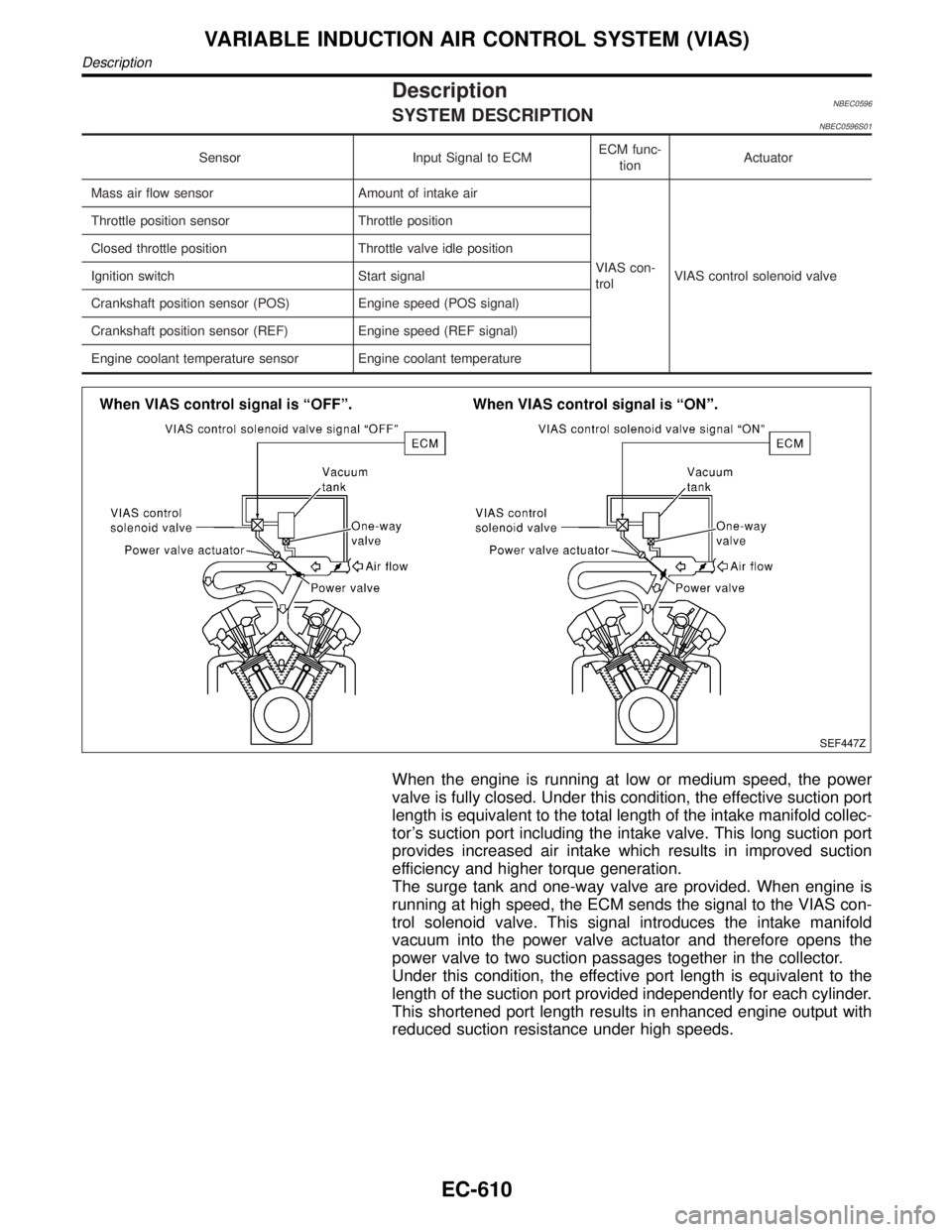
DescriptionNBEC0596SYSTEM DESCRIPTIONNBEC0596S01
Sensor Input Signal to ECMECM func-
tionActuator
Mass air flow sensor Amount of intake air
VIAS con-
trolVIAS control solenoid valve Throttle position sensor Throttle position
Closed throttle position Throttle valve idle position
Ignition switch Start signal
Crankshaft position sensor (POS) Engine speed (POS signal)
Crankshaft position sensor (REF) Engine speed (REF signal)
Engine coolant temperature sensor Engine coolant temperature
SEF447Z
When the engine is running at low or medium speed, the power
valve is fully closed. Under this condition, the effective suction port
length is equivalent to the total length of the intake manifold collec-
tor's suction port including the intake valve. This long suction port
provides increased air intake which results in improved suction
efficiency and higher torque generation.
The surge tank and one-way valve are provided. When engine is
running at high speed, the ECM sends the signal to the VIAS con-
trol solenoid valve. This signal introduces the intake manifold
vacuum into the power valve actuator and therefore opens the
power valve to two suction passages together in the collector.
Under this condition, the effective port length is equivalent to the
length of the suction port provided independently for each cylinder.
This shortened port length results in enhanced engine output with
reduced suction resistance under high speeds.
VARIABLE INDUCTION AIR CONTROL SYSTEM (VIAS)
Description
EC-610
Page 1151 of 2395

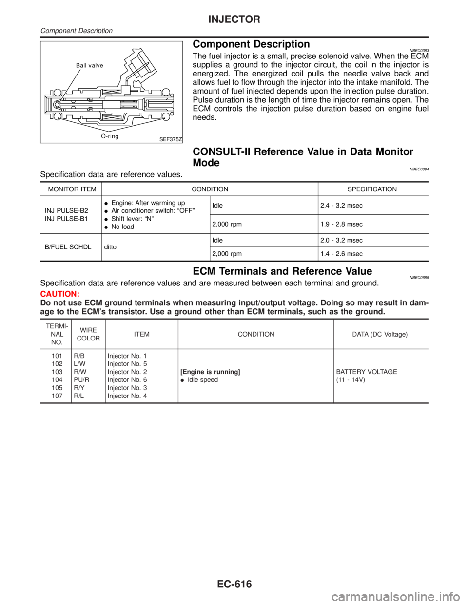
SEF375Z
Component DescriptionNBEC0383The fuel injector is a small, precise solenoid valve. When the ECM
supplies a ground to the injector circuit, the coil in the injector is
energized. The energized coil pulls the needle valve back and
allows fuel to flow through the injector into the intake manifold. The
amount of fuel injected depends upon the injection pulse duration.
Pulse duration is the length of time the injector remains open. The
ECM controls the injection pulse duration based on engine fuel
needs.
CONSULT-II Reference Value in Data Monitor
Mode
NBEC0384Specification data are reference values.
MONITOR ITEM CONDITION SPECIFICATION
INJ PULSE-B2
INJ PULSE-B1IEngine: After warming up
IAir conditioner switch: ªOFFº
IShift lever: ªNº
INo-loadIdle 2.4 - 3.2 msec
2,000 rpm 1.9 - 2.8 msec
B/FUEL SCHDL dittoIdle 2.0 - 3.2 msec
2,000 rpm 1.4 - 2.6 msec
ECM Terminals and Reference ValueNBEC0685Specification data are reference values and are measured between each terminal and ground.
CAUTION:
Do not use ECM ground terminals when measuring input/output voltage. Doing so may result in dam-
age to the ECM's transistor. Use a ground other than ECM terminals, such as the ground.
TERMI-
NAL
NO.WIRE
COLORITEM CONDITION DATA (DC Voltage)
101
102
103
104
105
107R/B
L/W
R/W
PU/R
R/Y
R/LInjector No. 1
Injector No. 5
Injector No. 2
Injector No. 6
Injector No. 3
Injector No. 4[Engine is running]
IIdle speedBATTERY VOLTAGE
(11 - 14V)
INJECTOR
Component Description
EC-616
Page 1219 of 2395

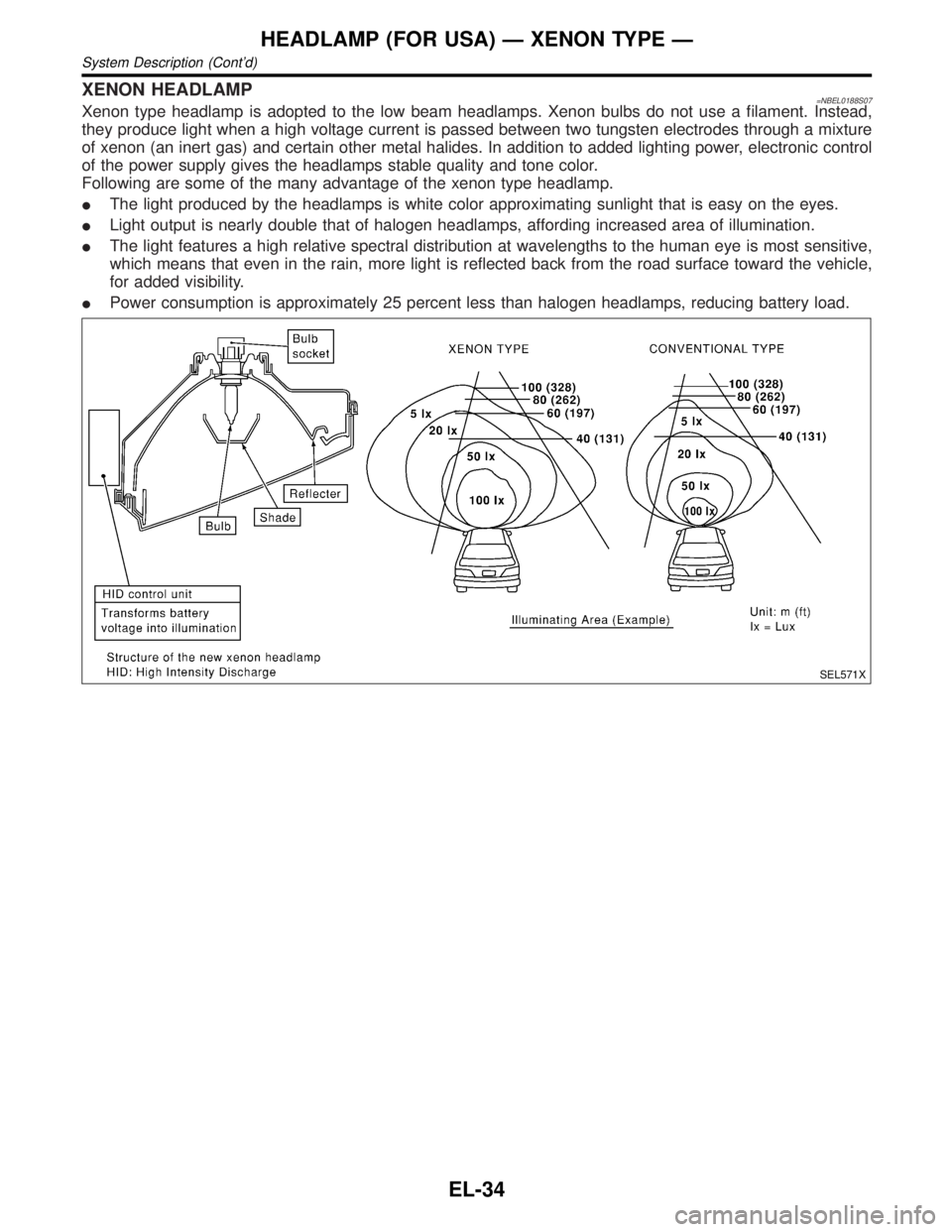
XENON HEADLAMP=NBEL0188S07Xenon type headlamp is adopted to the low beam headlamps. Xenon bulbs do not use a filament. Instead,
they produce light when a high voltage current is passed between two tungsten electrodes through a mixture
of xenon (an inert gas) and certain other metal halides. In addition to added lighting power, electronic control
of the power supply gives the headlamps stable quality and tone color.
Following are some of the many advantage of the xenon type headlamp.
IThe light produced by the headlamps is white color approximating sunlight that is easy on the eyes.
ILight output is nearly double that of halogen headlamps, affording increased area of illumination.
IThe light features a high relative spectral distribution at wavelengths to the human eye is most sensitive,
which means that even in the rain, more light is reflected back from the road surface toward the vehicle,
for added visibility.
IPower consumption is approximately 25 percent less than halogen headlamps, reducing battery load.
SEL571X
HEADLAMP (FOR USA) Ð XENON TYPE Ð
System Description (Cont'd)
EL-34