2001 INFINITI QX4 length
[x] Cancel search: lengthPage 1708 of 2395
SEM038F
SEM003F
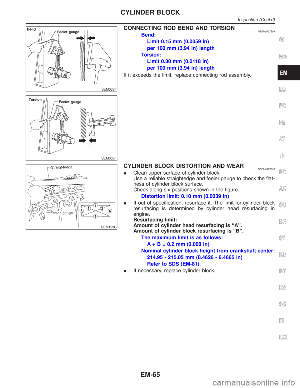
CONNECTING ROD BEND AND TORSIONNBEM0027S04Bend:
Limit 0.15 mm (0.0059 in)
per 100 mm (3.94 in) length
Torsion:
Limit 0.30 mm (0.0118 in)
per 100 mm (3.94 in) length
If it exceeds the limit, replace connecting rod assembly.
SEM123C
CYLINDER BLOCK DISTORTION AND WEARNBEM0027S05IClean upper surface of cylinder block.
Use a reliable straightedge and feeler gauge to check the flat-
ness of cylinder block surface.
Check along six positions shown in the figure.
Distortion limit: 0.10 mm (0.0039 in)
IIf out of specification, resurface it. The limit for cylinder block
resurfacing is determined by cylinder head resurfacing in
engine.
Resurfacing limit:
Amount of cylinder head resurfacing is ªAº.
Amount of cylinder block resurfacing is ªBº.
The maximum limit is as follows:
A + B = 0.2 mm (0.008 in)
Nominal cylinder block height from crankshaft center:
214.95 - 215.05 mm (8.4626 - 8.4665 in)
Refer to SDS (EM-81).
IIf necessary, replace cylinder block.
GI
MA
LC
EC
FE
AT
TF
PD
AX
SU
BR
ST
RS
BT
HA
SC
EL
IDX
CYLINDER BLOCK
Inspection (Cont'd)
EM-65
Page 1719 of 2395
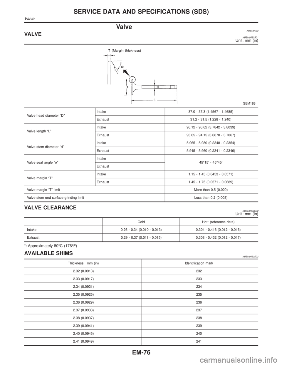
ValveNBEM0032VALVENBEM0032S01Unit: mm (in)
SEM188
Valve head diameter ªDºIntake 37.0 - 37.3 (1.4567 - 1.4685)
Exhaust 31.2 - 31.5 (1.228 - 1.240)
Valve length ªLºIntake 96.12 - 96.62 (3.7842 - 3.8039)
Exhaust 93.65 - 94.15 (3.6870 - 3.7067)
Valve stem diameter ªdºIntake 5.965 - 5.980 (0.2348 - 0.2354)
Exhaust 5.945 - 5.960 (0.2341 - 0.2346)
Valve seat angle ªaºIntake
45É15¢- 45É45¢
Exhaust
Valve margin ªTºIntake 1.15 - 1.45 (0.0453 - 0.0571)
Exhaust 1.45 - 1.75 (0.0571 - 0.0689)
Valve margin ªTº limitMore than 0.5 (0.020)
Valve stem end surface grinding limit Less than 0.2 (0.008)
VALVE CLEARANCENBEM0032S02Unit: mm (in)
Cold Hot* (reference data)
Intake 0.26 - 0.34 (0.010 - 0.013) 0.304 - 0.416 (0.012 - 0.016)
Exhaust 0.29 - 0.37 (0.011 - 0.015) 0.308 - 0.432 (0.012 - 0.017)
*: Approximately 80ÉC (176ÉF)
AVAILABLE SHIMSNBEM0032S03
Thickness mm (in) Identification mark
2.32 (0.0913) 232
2.33 (0.0917) 233
2.34 (0.0921) 234
2.35 (0.0925) 235
2.36 (0.0929) 236
2.37 (0.0933) 237
2.38 (0.0937) 238
2.39 (0.0941) 239
2.40 (0.0945) 240
2.41 (0.0949) 241
SERVICE DATA AND SPECIFICATIONS (SDS)
Valve
EM-76
Page 1722 of 2395
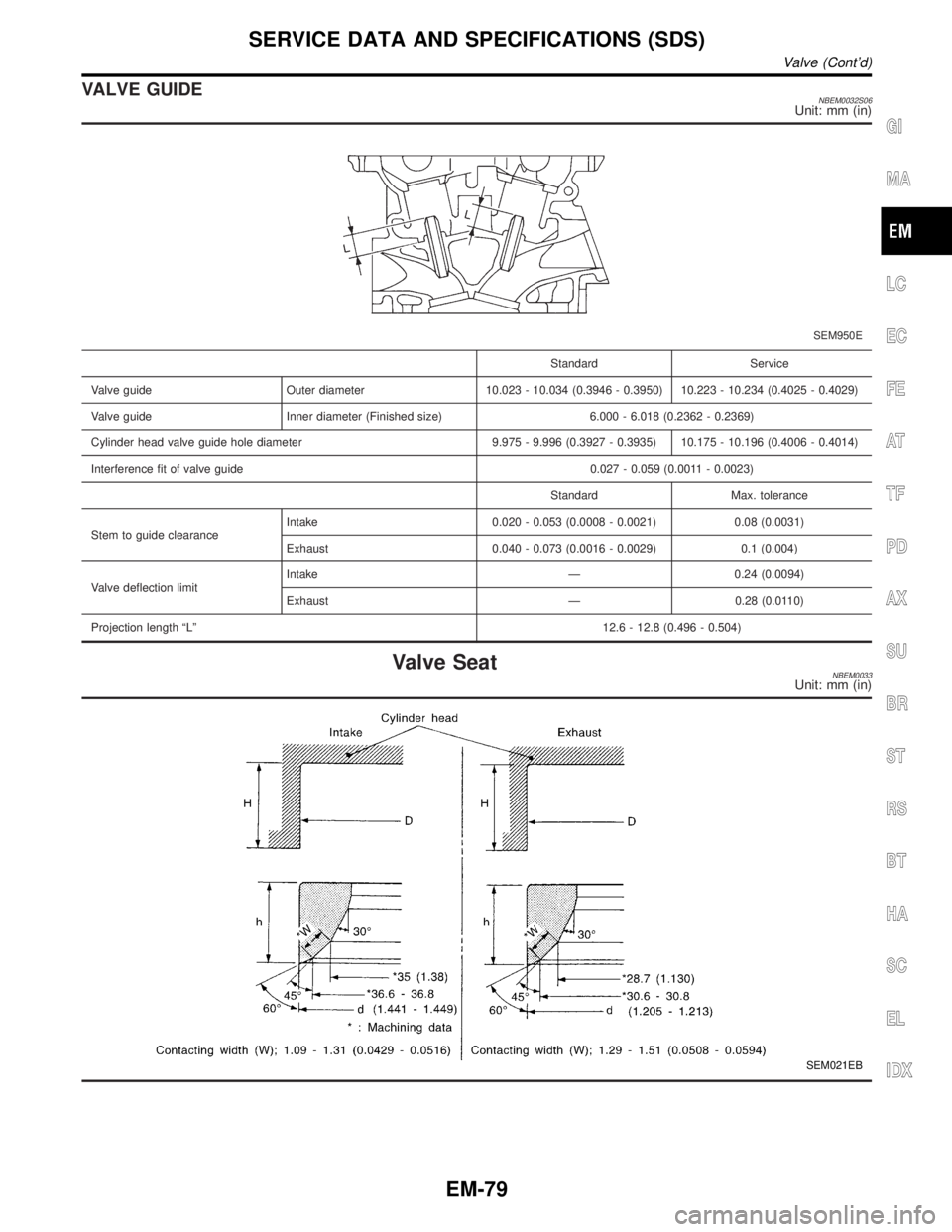
VALVE GUIDENBEM0032S06Unit: mm (in)
SEM950E
Standard Service
Valve guide Outer diameter 10.023 - 10.034 (0.3946 - 0.3950) 10.223 - 10.234 (0.4025 - 0.4029)
Valve guide Inner diameter (Finished size) 6.000 - 6.018 (0.2362 - 0.2369)
Cylinder head valve guide hole diameter 9.975 - 9.996 (0.3927 - 0.3935) 10.175 - 10.196 (0.4006 - 0.4014)
Interference fit of valve guide 0.027 - 0.059 (0.0011 - 0.0023)
Standard Max. tolerance
Stem to guide clearanceIntake 0.020 - 0.053 (0.0008 - 0.0021) 0.08 (0.0031)
Exhaust 0.040 - 0.073 (0.0016 - 0.0029) 0.1 (0.004)
Valve deflection limitIntake Ð 0.24 (0.0094)
Exhaust Ð 0.28 (0.0110)
Projection length ªLº12.6 - 12.8 (0.496 - 0.504)
Valve SeatNBEM0033Unit: mm (in)
SEM021EB
GI
MA
LC
EC
FE
AT
TF
PD
AX
SU
BR
ST
RS
BT
HA
SC
EL
IDX
SERVICE DATA AND SPECIFICATIONS (SDS)
Valve (Cont'd)
EM-79
Page 1752 of 2395
Do not place the vehicle on flammable material. Keep flammable
material off the exhaust pipe and the three way catalyst.
SMA019D
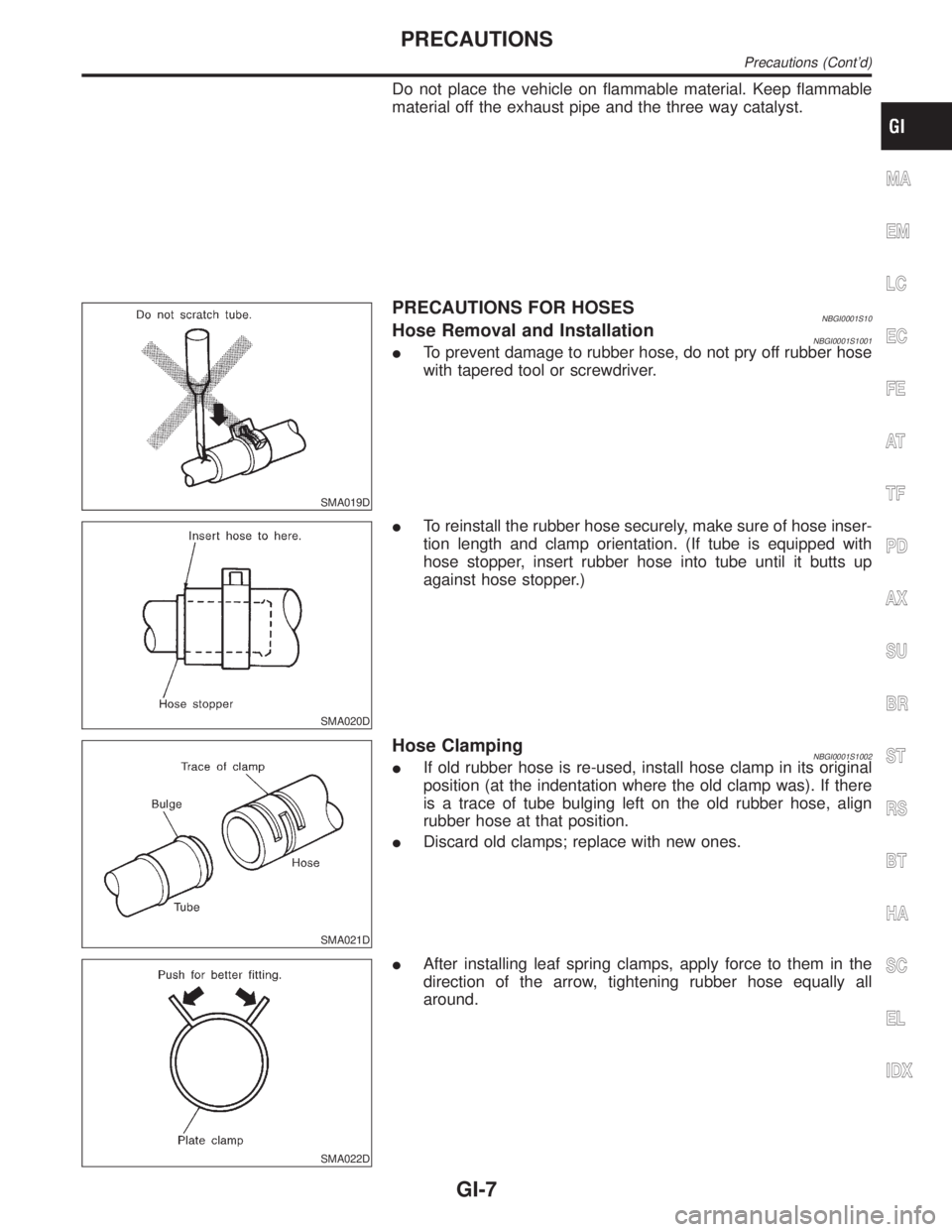
PRECAUTIONS FOR HOSESNBGI0001S10Hose Removal and InstallationNBGI0001S1001ITo prevent damage to rubber hose, do not pry off rubber hose
with tapered tool or screwdriver.
SMA020D
ITo reinstall the rubber hose securely, make sure of hose inser-
tion length and clamp orientation. (If tube is equipped with
hose stopper, insert rubber hose into tube until it butts up
against hose stopper.)
SMA021D
Hose ClampingNBGI0001S1002IIf old rubber hose is re-used, install hose clamp in its original
position (at the indentation where the old clamp was). If there
is a trace of tube bulging left on the old rubber hose, align
rubber hose at that position.
IDiscard old clamps; replace with new ones.
SMA022D
IAfter installing leaf spring clamps, apply force to them in the
direction of the arrow, tightening rubber hose equally all
around.
MA
EM
LC
EC
FE
AT
TF
PD
AX
SU
BR
ST
RS
BT
HA
SC
EL
IDX
PRECAUTIONS
Precautions (Cont'd)
GI-7
Page 1788 of 2395

SGI136A
ENGINE SERIAL NUMBERNBGI0007S0203
MGI042A
AUTOMATIC TRANSMISSION NUMBERNBGI0007S0204
MGI043A
TRANSFER SERIAL NUMBERNBGI0007S0205
DimensionsNBGI0007S03Unit: mm (in)
Wagon
VQ35DE
Overall length 4,650 (183.1)
Overall width 1,840 (72.4)
Overall height1,730 (68.1)
1,795 (70.7)*
Front tread 1,540 (60.6)
Rear tread 1,545 (60.8)
Wheelbase 2,700 (106.3)
*: With luggage rack
MA
EM
LC
EC
FE
AT
TF
PD
AX
SU
BR
ST
RS
BT
HA
SC
EL
IDX
IDENTIFICATION INFORMATION
Identification Number (Cont'd)
GI-43
Page 1918 of 2395
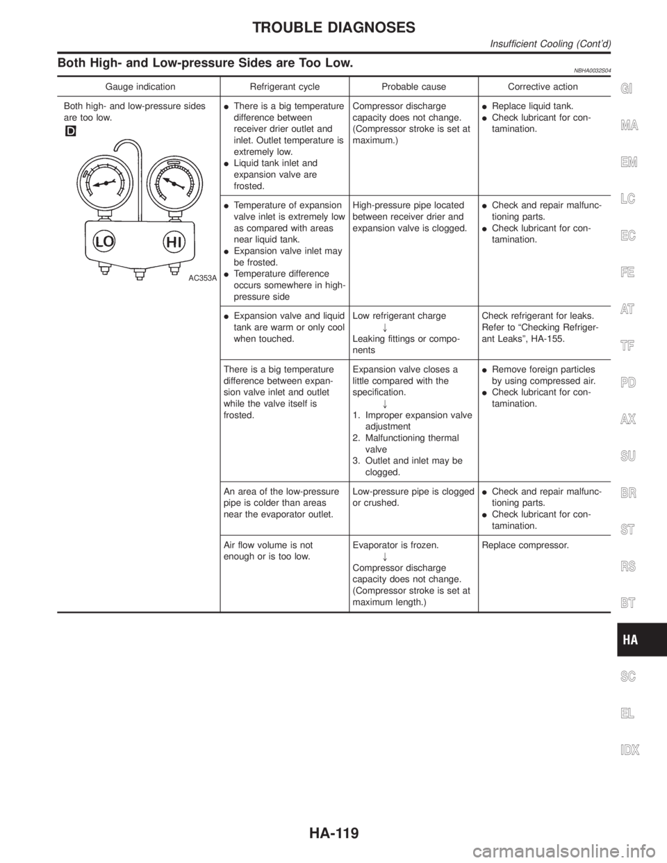
Both High- and Low-pressure Sides are Too Low.NBHA0032S04
Gauge indication Refrigerant cycle Probable cause Corrective action
Both high- and low-pressure sides
are too low.
AC353A
IThere is a big temperature
difference between
receiver drier outlet and
inlet. Outlet temperature is
extremely low.
ILiquid tank inlet and
expansion valve are
frosted.Compressor discharge
capacity does not change.
(Compressor stroke is set at
maximum.)IReplace liquid tank.
ICheck lubricant for con-
tamination.
ITemperature of expansion
valve inlet is extremely low
as compared with areas
near liquid tank.
IExpansion valve inlet may
be frosted.
ITemperature difference
occurs somewhere in high-
pressure sideHigh-pressure pipe located
between receiver drier and
expansion valve is clogged.ICheck and repair malfunc-
tioning parts.
ICheck lubricant for con-
tamination.
IExpansion valve and liquid
tank are warm or only cool
when touched.Low refrigerant charge
"
Leaking fittings or compo-
nentsCheck refrigerant for leaks.
Refer to ªChecking Refriger-
ant Leaksº, HA-155.
There is a big temperature
difference between expan-
sion valve inlet and outlet
while the valve itself is
frosted.Expansion valve closes a
little compared with the
specification.
"
1. Improper expansion valve
adjustment
2. Malfunctioning thermal
valve
3. Outlet and inlet may be
clogged.IRemove foreign particles
by using compressed air.
ICheck lubricant for con-
tamination.
An area of the low-pressure
pipe is colder than areas
near the evaporator outlet.Low-pressure pipe is clogged
or crushed.ICheck and repair malfunc-
tioning parts.
ICheck lubricant for con-
tamination.
Air flow volume is not
enough or is too low.Evaporator is frozen.
"
Compressor discharge
capacity does not change.
(Compressor stroke is set at
maximum length.)Replace compressor.
GI
MA
EM
LC
EC
FE
AT
TF
PD
AX
SU
BR
ST
RS
BT
SC
EL
IDX
TROUBLE DIAGNOSES
Insufficient Cooling (Cont'd)
HA-119
Page 1964 of 2395
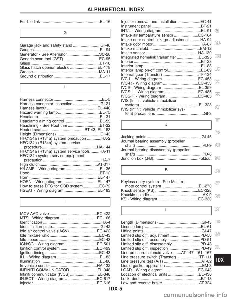
Fusible link ......................................................EL-16
G
Garage jack and safety stand .........................GI-46
Gauges............................................................EL-94
Generator - See Alternator .............................SC-28
Generic scan tool (GST) ................................EC-95
Glass ...............................................................BT-18
Glass hatch opener, electric .........................EL-178
Grease ............................................................MA-11
Ground distribution..........................................EL-17
H
Harness connector ............................................EL-5
Harness connector inspection .........................GI-21
Harness layout ..............................................EL-440
Hazard warning lamp ......................................EL-75
Headlamp ........................................................EL-31
Headlamp aiming control ................................EL-59
Headlining - See Roof trim .............................BT-32
Heated seat .......................................BT-43, EL-183
Height (Dimensions) ........................................GI-43
HFC134a (R134a) system precaution .............HA-2
HFC134a (R134a) system service
procedure ..................................................HA-144
HFC134a (R134a) system service tools ........HA-11
HFC134a system service equipment
precaution .....................................................HA-7
High clutch.....................................................AT-317
H/LAMP - Wiring diagram ...............................EL-36
Hood................................................................BT-12
Horn ..............................................................EL-147
HORN - Wiring diagram................................EL-147
How to erase DTC for OBD system...............EC-72
HSEAT - Wiring diagram...............................EL-183
I
IACV-AAC valve ...........................................EC-422
IATS - Wiring diagram ..................................EC-166
Identification .....................................................HA-4
Identification plate............................................GI-42
Idle air control valve (IACV) .........................EC-422
Idle mixture ratio.............................................EC-43
Idle speed .......................................................EC-43
IGN/SG - Wiring diagram .............................EC-501
Ignition control system .................................EC-499
Ignition timing .................................................EC-43
ILL - Wiring diagram .......................................EL-83
Illumination ......................................................EL-80
In vehicle sensor ..........................................HA-132
INFINITI COMMUNICATOR..........................EL-348
Infiniti communicator (IVCS) .........................EL-348
INJECT - Wiring diagram .............................EC-617
Injector ..........................................................EC-616Injector removal and installation ....................EC-41
Instrument panel .............................................BT-21
INT/L - Wiring diagram....................................EL-91
Intake air temparature sensor ......................EC-164
Intake door control linkage adjustment ..........HA-94
Intake door motor ...........................................HA-87
Intake manifold...............................................EM-12
Intake sensor ................................................HA-139
Integrated homelink transmitter ....................EL-325
Interior .............................................................BT-28
Interior lamp ....................................................EL-88
Interior lamp on-off control ..............................EL-89
Internal gear (Transfer) .................................TF-134
IVC-L - Wiring diagram.................................EC-453
IVC-R - Wiring diagram ................................EC-453
IVCS - Wiring diagram ..................................EL-359
IVCS-L - Wiring diagram ..............................EC-485
IVCS-R - Wiring diagram .............................EC-485
IVIS (Infiniti vehicle immobilizer
system) ......................................................EL-328
IVIS (Infiniti vehicle immobilizer sys-
tem) precautions ............................................GI-3
J
Jacking points ..................................................GI-45
Journal bearing assembly (propeller
shaft) .............................................................PD-9
Journal bearing disassembly (propeller
shaft) .............................................................PD-8
Junction box (J/B).........................................Foldout
K
Keyless entry system - See Multi-re-
mote control system ..................................EL-270
Knock sensor (KS) .......................................EC-328
Knuckle spindle ................................................AX-9
KS - Wiring diagram .....................................EC-330
L
Length (Dimensions) .......................................GI-43
License lamp ...................................................EL-61
Lifting points ....................................................GI-47
Limited slip diff. adjustment ............................PD-50
Limited slip diff. assembly ..............................PD-51
Limited slip diff. disassembly..........................PD-48
Limited slip diff. inspection .............................PD-49
Line pressure solenoid valve ........AT-147, 161, 167
Line pressure switch (Transfer) .....................TF-111
Line pressure test (A/T) ..................................AT-62
Liquid gasket application .................................EM-3
LOAD - Wiring diagram ................................EC-643
Location of electrical units ............................EL-436
Lock, door .......................................................BT-18
Low and reverse brake .................................AT-324
GI
MA
EM
LC
EC
FE
AT
TF
PD
AX
SU
BR
ST
RS
BT
HA
SC
EL
ALPHABETICAL INDEX
IDX-5
Page 2036 of 2395
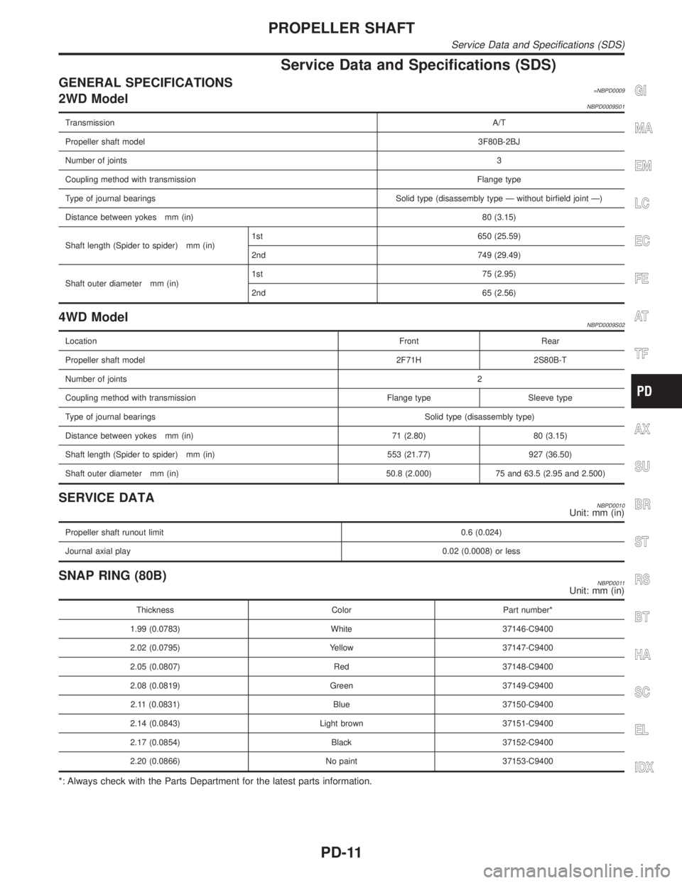
Service Data and Specifications (SDS)
GENERAL SPECIFICATIONS=NBPD00092WD ModelNBPD0009S01
TransmissionA/T
Propeller shaft model3F80B-2BJ
Number of joints3
Coupling method with transmissionFlange type
Type of journal bearings Solid type (disassembly type Ð without birfield joint Ð)
Distance between yokes mm (in)80 (3.15)
Shaft length (Spider to spider) mm (in)1st 650 (25.59)
2nd 749 (29.49)
Shaft outer diameter mm (in)1st 75 (2.95)
2nd 65 (2.56)
4WD ModelNBPD0009S02
LocationFront Rear
Propeller shaft model 2F71H 2S80B-T
Number of joints2
Coupling method with transmission Flange type Sleeve type
Type of journal bearingsSolid type (disassembly type)
Distance between yokes mm (in) 71 (2.80) 80 (3.15)
Shaft length (Spider to spider) mm (in) 553 (21.77) 927 (36.50)
Shaft outer diameter mm (in) 50.8 (2.000) 75 and 63.5 (2.95 and 2.500)
SERVICE DATANBPD0010Unit: mm (in)
Propeller shaft runout limit0.6 (0.024)
Journal axial play0.02 (0.0008) or less
SNAP RING (80B)NBPD0011Unit: mm (in)
Thickness Color Part number*
1.99 (0.0783) White 37146-C9400
2.02 (0.0795) Yellow 37147-C9400
2.05 (0.0807) Red 37148-C9400
2.08 (0.0819) Green 37149-C9400
2.11 (0.0831) Blue 37150-C9400
2.14 (0.0843) Light brown 37151-C9400
2.17 (0.0854) Black 37152-C9400
2.20 (0.0866) No paint 37153-C9400
*: Always check with the Parts Department for the latest parts information.
GI
MA
EM
LC
EC
FE
AT
TF
AX
SU
BR
ST
RS
BT
HA
SC
EL
IDX
PROPELLER SHAFT
Service Data and Specifications (SDS)
PD-11