Page 429 of 2395
MBR440A
DESCRIPTIONABS
Wiring Diagram Ð ABS Ð (Cont'd)
BR-40
Page 430 of 2395

Self-diagnosisNBBR0095FUNCTIONNBBR0095S01IWhen a problem occurs in the ABS, the warning lamp on the
instrument panel comes on. To start the self-diagnostic results
mode, ground the self-diagnostic (check) terminal located on
data link connector. The location of the malfunction is indicated
by the warning lamp flashing.
SELF-DIAGNOSIS PROCEDURENBBR0095S021. Drive vehicle over 30 km/h (19 MPH) for at least one minute.
2. Turn ignition switch OFF.
SBR665E
3. Ground terminal 9 of data link connector with a suitable har-
ness.
4. Turn ignition switch ON while grounding terminal 9.
Do not depress brake pedal.
SBR668E
5. After 3.0 seconds, the warning lamp starts flashing to indicate
the malfunction code No. (See NOTE.)
6. Verify the location of the malfunction with the malfunction code
chart. Refer to BR-54. Then make the necessary repairs fol-
lowing the diagnostic procedures.
7. After the malfunctions are repaired, erase the malfunction
codes stored in the control unit. Refer to BR-42.
8. Rerun the self-diagnostic results mode to verify that the mal-
function codes have been erased.
9. Disconnect the check terminal from the ground. The self-diag-
nostic results mode is now complete.
10. Check warning lamp for deactivation after driving vehicle over
30 km/h (19 MPH) for at least one minute.
11. After making certain that warning lamp does not come on, test
the ABS in a safe area to verify that it functions properly.
NOTE:
The indication terminates after 5 minutes.
However, when the ignition switch is turned from OFF to ON, the
indication starts flashing again.
GI
MA
EM
LC
EC
FE
AT
TF
PD
AX
SU
ST
RS
BT
HA
SC
EL
IDX
ON BOARD DIAGNOSTIC SYSTEM DESCRIPTIONABS
Self-diagnosis
BR-41
Page 431 of 2395
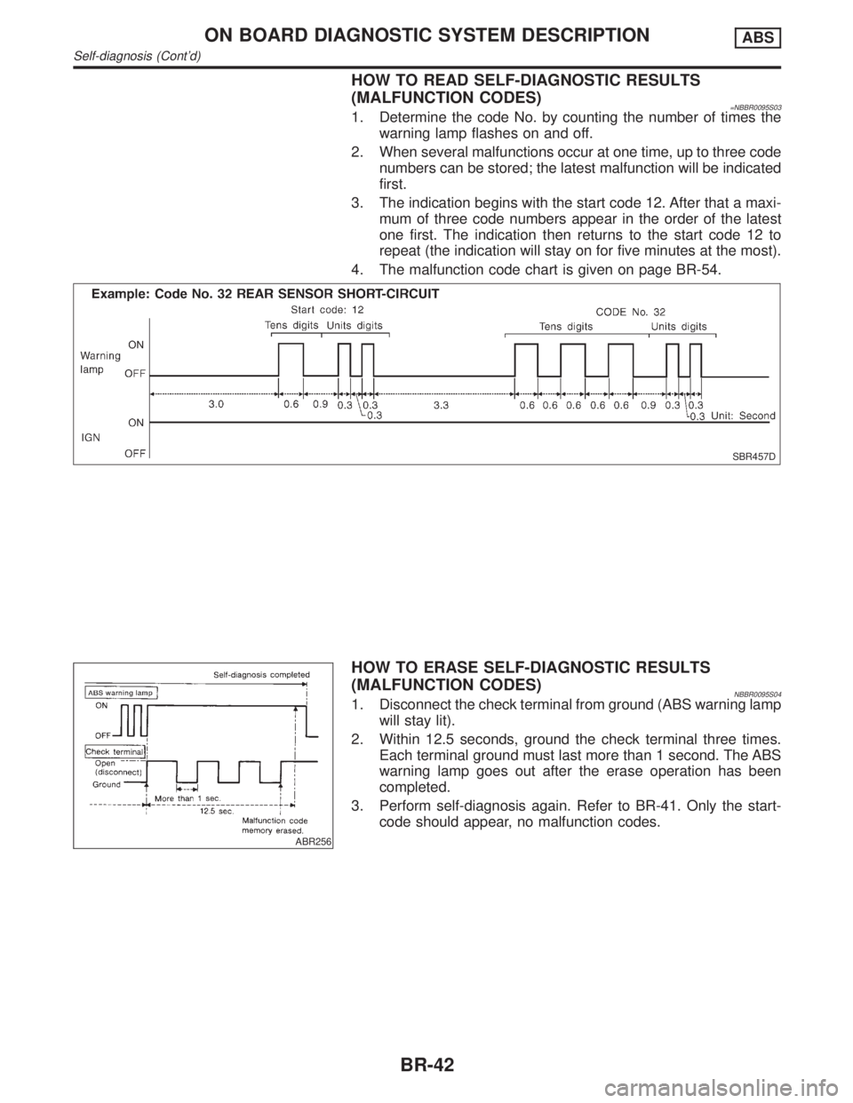
HOW TO READ SELF-DIAGNOSTIC RESULTS
(MALFUNCTION CODES)
=NBBR0095S031. Determine the code No. by counting the number of times the
warning lamp flashes on and off.
2. When several malfunctions occur at one time, up to three code
numbers can be stored; the latest malfunction will be indicated
first.
3. The indication begins with the start code 12. After that a maxi-
mum of three code numbers appear in the order of the latest
one first. The indication then returns to the start code 12 to
repeat (the indication will stay on for five minutes at the most).
4. The malfunction code chart is given on page BR-54.
SBR457D
ABR256
HOW TO ERASE SELF-DIAGNOSTIC RESULTS
(MALFUNCTION CODES)
NBBR0095S041. Disconnect the check terminal from ground (ABS warning lamp
will stay lit).
2. Within 12.5 seconds, ground the check terminal three times.
Each terminal ground must last more than 1 second. The ABS
warning lamp goes out after the erase operation has been
completed.
3. Perform self-diagnosis again. Refer to BR-41. Only the start-
code should appear, no malfunction codes.
ON BOARD DIAGNOSTIC SYSTEM DESCRIPTIONABS
Self-diagnosis (Cont'd)
BR-42
Page 432 of 2395

CONSULT-II=NBBR0096CONSULT-II APPLICATION TO ABSNBBR0096S01
ITEMSELF-DIAGNOSTIC
RESULTSDATA MONITOR ACTIVE TEST
Front right wheel sensor´´Ð
Front left wheel sensor´´Ð
Rear right wheel sensor´´Ð
Rear left wheel sensor´´Ð
G switch (G sensor)H´´´
ABS sensor´ÐÐ
Stop lamp switch дÐ
Front right inlet solenoid valve´´´
Front right outlet solenoid valve´´´
Front left inlet solenoid valve´´´
Front left outlet solenoid valve´´´
Rear inlet solenoid valve´´´
Rear outlet solenoid valve´´´
Actuator solenoid valve relay´´Ð
Actuator motor relay
(ABS MOTOR is shown on the Data Monitor
screen.)´´´
ABS warning lamp дÐ
Battery voltage´´Ð
Control unit´ÐÐ
ABS operating signal д´
´: Applicable
Ð: Not applicable
H: 4WD models only
ECU (ABS CONTROL UNIT) PART NUMBER MODENBBR0096S02Ignore the ECU part number displayed in the ECU PART NUMBER MODE. Refer to parts catalog to order
the ECU.
GI
MA
EM
LC
EC
FE
AT
TF
PD
AX
SU
ST
RS
BT
HA
SC
EL
IDX
ON BOARD DIAGNOSTIC SYSTEM DESCRIPTIONABS
CONSULT-II
BR-43
Page 433 of 2395

SBR665E
CONSULT-II Inspection Procedure=NBBR0097SELF-DIAGNOSIS PROCEDURENBBR0097S011. Turn ignition switch OFF.
2. Connect CONSULT-II to data link connector.
3. Start engine.
4. Drive vehicle over 30 km/h (19 MPH) for at least one minute.
PBR455D
5. Stop vehicle with engine running and touch ªSTARTº on CON-
SULT-II screen.
SBR670E
6. Touch ªABSº.
SBR636E
7. Touch ªSELF-DIAG RESULTSº.
IThe screen shows the detected malfunction and how many
times the ignition switch has been turned ON since the mal-
function.
8. Make the necessary repairs following the diagnostic proce-
dures.
PBR950C
9. After the malfunctions are repaired, erase the self-diagnostic
results stored in the control unit by touching ªERASEº.
10. Check warning lamp for deactivation after driving vehicle over
30 km/h (19 MPH) for at least one minute.
11. Test the ABS in a safe area to verify that it functions properly.
NOTE:
ªSELF-DIAG RESULTSº screen shows the detected malfunction
and how many times the ignition switch has been turned since the
malfunction.
ON BOARD DIAGNOSTIC SYSTEM DESCRIPTIONABS
CONSULT-II Inspection Procedure
BR-44
Page 434 of 2395
![INFINITI QX4 2001 Factory Service Manual SELF-DIAGNOSTIC RESULTS MODENBBR0097S02
Diagnostic item Diagnostic item is detected when ... Reference Page
FR RH SENSOR*1
[OPEN]ICircuit for front right wheel sensor is open.
(An abnormally high inpu](/manual-img/42/57027/w960_57027-433.png "INFINITI QX4 2001 Factory Service Manual SELF-DIAGNOSTIC RESULTS MODENBBR0097S02
Diagnostic item Diagnostic item is detected when ... Reference Page
FR RH SENSOR*1
[OPEN]ICircuit for front right wheel sensor is open.
(An abnormally high inpu")
SELF-DIAGNOSTIC RESULTS MODENBBR0097S02
Diagnostic item Diagnostic item is detected when ... Reference Page
FR RH SENSOR*1
[OPEN]ICircuit for front right wheel sensor is open.
(An abnormally high input voltage is entered.)BR-56
FR LH SENSOR*1
[OPEN]ICircuit for front left wheel sensor is open.
(An abnormally high input voltage is entered.)BR-56
RR RH SENSOR*1
[OPEN]ICircuit for rear right sensor is open.
(An abnormally high input voltage is entered.)BR-56
RR LH SENSOR*1
[OPEN]ICircuit for rear left sensor is open.
(An abnormally high input voltage is entered.)BR-56
FR RH SENSOR*1
[SHORT]ICircuit for front right wheel sensor is shorted.
(An abnormally low input voltage is entered.)BR-56
FR LH SENSOR*1
[SHORT]ICircuit for front left wheel sensor is shorted.
(An abnormally low input voltage is entered.)BR-56
RR RH SENSOR*1
[SHORT]ICircuit for rear right sensor is shorted.
(An abnormally low input voltage is entered.)BR-56
RR LH SENSOR*1
[SHORT]ICircuit for rear left sensor is shorted.
(An abnormally low input voltage is entered.)BR-56
ABS SENSOR*1
[ABNORMAL SIGNAL]ITeeth damage on sensor rotor or improper installation of wheel sensor.
(Abnormal wheel sensor signal is entered.)BR-56
FR RH IN ABS SOL
[OPEN, SHORT]ICircuit for front right inlet solenoid valve is open.
(An abnormally low output voltage is entered.)BR-59
FR LH IN ABS SOL
[OPEN, SHORT]ICircuit for front left inlet solenoid valve is open.
(An abnormally low output voltage is entered.)BR-59
FR RH OUT ABS SOL
[OPEN, SHORT]ICircuit for front right outlet solenoid valve is open.
(An abnormally low output voltage is entered.)BR-59
FR LH OUT ABS SOL
[OPEN, SHORT]ICircuit for front left outlet solenoid valve is open.
(An abnormally low output voltage is entered.)BR-59
RR IN ABS SOL
[OPEN, SHORT]ICircuit for rear inlet solenoid valve is shorted.
(An abnormally high output voltage is entered.)BR-59
RR OUT ABS SOL
[OPEN, SHORT]ICircuit for rear out solenoid valve is shorted.
(An abnormally high output voltage is entered.)BR-59
ABS ACTUATOR RELAY
[ABNORMAL]IActuator solenoid valve relay is ON, even if control unit sends off signal.
IActuator solenoid valve relay is OFF, even if control unit sends on signal.BR-59
ABS MOTOR RELAY
[ABNORMAL]ICircuit for ABS motor relay is open or shorted.
ICircuit for actuator motor is open or shorted.
IActuator motor relay is stuck.BR-61
BATTERY VOLT
[VB-LOW]IPower source voltage supplied to ABS control unit is abnormally low.
BR-63
CONTROL UNITIFunction of calculation in ABS control unit has failed. BR-68
G SENSOR*2
[ABNORMAL]IG sensor circuit is open or shorted.
BR-65
*1: If one or more wheels spin on a rough or slippery road for 40 seconds or more, the ABS warning lamp will illuminate. This does not
indicate a malfunction. Only in the case of the short-circuit (Code Nos. 26, 22, 32 and 36), after repair the ABS warning lamp also illu-
minates when the ignition switch is turned ON. In this case, drive the vehicle at speeds greater than 30 km/h (19 MPH) for approxi-
mately 1 minute as specified in ªSELF-DIAGNOSIS PROCEDUREº, BR-41. Check to ensure that the ABS warning lamp goes out while
the vehicle is being driven.
*2: 4WD models onlyGI
MA
EM
LC
EC
FE
AT
TF
PD
AX
SU
ST
RS
BT
HA
SC
EL
IDX
ON BOARD DIAGNOSTIC SYSTEM DESCRIPTIONABS
CONSULT-II Inspection Procedure (Cont'd)
BR-45
Page 435 of 2395
PBR455D
DATA MONITOR PROCEDURENBBR0097S031. Turn ignition switch OFF.
2. Connect CONSULT-II to data link connector.
3. Turn ignition switch ON.
4. Touch ªSTARTº on CONSULT-II screen.
SBR670E
5. Touch ªABSº.
SBR636E
6. Touch ªDATA MONITORº.
SBR637E
7. Touch ªSETTINGº on ªSELECT MONITOR ITEMº screen.
ON BOARD DIAGNOSTIC SYSTEM DESCRIPTIONABS
CONSULT-II Inspection Procedure (Cont'd)
BR-46
Page 436 of 2395
PBR455D
ACTIVE TEST PROCEDURE=NBBR0097S04IWhen conducting Active test, vehicle must be stationary.
IWhen ABS warning lamp stays on, never conduct Active test.
1. Turn ignition switch OFF.
2. Connect CONSULT-II to data link connector.
3. Start engine.
4. Touch ªSTARTº on CONSULT-II screen.
SBR670E
5. Touch ªABSº.
SBR636E
6. Touch ªACTIVE TESTº.
SBR671E
7. Select active test item by touching screen.
SBR639E
8. Touch ªSTARTº.
9. Carry out the active test by touching screen key.
GI
MA
EM
LC
EC
FE
AT
TF
PD
AX
SU
ST
RS
BT
HA
SC
EL
IDX
ON BOARD DIAGNOSTIC SYSTEM DESCRIPTIONABS
CONSULT-II Inspection Procedure (Cont'd)
BR-47


