Page 434 of 2395
![INFINITI QX4 2001 Factory Service Manual SELF-DIAGNOSTIC RESULTS MODENBBR0097S02
Diagnostic item Diagnostic item is detected when ... Reference Page
FR RH SENSOR*1
[OPEN]ICircuit for front right wheel sensor is open.
(An abnormally high inpu INFINITI QX4 2001 Factory Service Manual SELF-DIAGNOSTIC RESULTS MODENBBR0097S02
Diagnostic item Diagnostic item is detected when ... Reference Page
FR RH SENSOR*1
[OPEN]ICircuit for front right wheel sensor is open.
(An abnormally high inpu](/manual-img/42/57027/w960_57027-433.png)
SELF-DIAGNOSTIC RESULTS MODENBBR0097S02
Diagnostic item Diagnostic item is detected when ... Reference Page
FR RH SENSOR*1
[OPEN]ICircuit for front right wheel sensor is open.
(An abnormally high input voltage is entered.)BR-56
FR LH SENSOR*1
[OPEN]ICircuit for front left wheel sensor is open.
(An abnormally high input voltage is entered.)BR-56
RR RH SENSOR*1
[OPEN]ICircuit for rear right sensor is open.
(An abnormally high input voltage is entered.)BR-56
RR LH SENSOR*1
[OPEN]ICircuit for rear left sensor is open.
(An abnormally high input voltage is entered.)BR-56
FR RH SENSOR*1
[SHORT]ICircuit for front right wheel sensor is shorted.
(An abnormally low input voltage is entered.)BR-56
FR LH SENSOR*1
[SHORT]ICircuit for front left wheel sensor is shorted.
(An abnormally low input voltage is entered.)BR-56
RR RH SENSOR*1
[SHORT]ICircuit for rear right sensor is shorted.
(An abnormally low input voltage is entered.)BR-56
RR LH SENSOR*1
[SHORT]ICircuit for rear left sensor is shorted.
(An abnormally low input voltage is entered.)BR-56
ABS SENSOR*1
[ABNORMAL SIGNAL]ITeeth damage on sensor rotor or improper installation of wheel sensor.
(Abnormal wheel sensor signal is entered.)BR-56
FR RH IN ABS SOL
[OPEN, SHORT]ICircuit for front right inlet solenoid valve is open.
(An abnormally low output voltage is entered.)BR-59
FR LH IN ABS SOL
[OPEN, SHORT]ICircuit for front left inlet solenoid valve is open.
(An abnormally low output voltage is entered.)BR-59
FR RH OUT ABS SOL
[OPEN, SHORT]ICircuit for front right outlet solenoid valve is open.
(An abnormally low output voltage is entered.)BR-59
FR LH OUT ABS SOL
[OPEN, SHORT]ICircuit for front left outlet solenoid valve is open.
(An abnormally low output voltage is entered.)BR-59
RR IN ABS SOL
[OPEN, SHORT]ICircuit for rear inlet solenoid valve is shorted.
(An abnormally high output voltage is entered.)BR-59
RR OUT ABS SOL
[OPEN, SHORT]ICircuit for rear out solenoid valve is shorted.
(An abnormally high output voltage is entered.)BR-59
ABS ACTUATOR RELAY
[ABNORMAL]IActuator solenoid valve relay is ON, even if control unit sends off signal.
IActuator solenoid valve relay is OFF, even if control unit sends on signal.BR-59
ABS MOTOR RELAY
[ABNORMAL]ICircuit for ABS motor relay is open or shorted.
ICircuit for actuator motor is open or shorted.
IActuator motor relay is stuck.BR-61
BATTERY VOLT
[VB-LOW]IPower source voltage supplied to ABS control unit is abnormally low.
BR-63
CONTROL UNITIFunction of calculation in ABS control unit has failed. BR-68
G SENSOR*2
[ABNORMAL]IG sensor circuit is open or shorted.
BR-65
*1: If one or more wheels spin on a rough or slippery road for 40 seconds or more, the ABS warning lamp will illuminate. This does not
indicate a malfunction. Only in the case of the short-circuit (Code Nos. 26, 22, 32 and 36), after repair the ABS warning lamp also illu-
minates when the ignition switch is turned ON. In this case, drive the vehicle at speeds greater than 30 km/h (19 MPH) for approxi-
mately 1 minute as specified in ªSELF-DIAGNOSIS PROCEDUREº, BR-41. Check to ensure that the ABS warning lamp goes out while
the vehicle is being driven.
*2: 4WD models onlyGI
MA
EM
LC
EC
FE
AT
TF
PD
AX
SU
ST
RS
BT
HA
SC
EL
IDX
ON BOARD DIAGNOSTIC SYSTEM DESCRIPTIONABS
CONSULT-II Inspection Procedure (Cont'd)
BR-45
Page 437 of 2395

DATA MONITOR MODENBBR0097S05
MONITOR ITEM CONDITION SPECIFICATION
FR RH SENSOR
FR LH SENSOR
RR RH SENSOR
RR LH SENSORDrive vehicle.
(Each wheel is rotating.)Wheel speed signal
(Almost the same speed as speedometer.)
STOP LAMP SW Brake is depressed.Depress the pedal: ON
Release the pedal: OFF
G-SWITCHHVehicle is driven.
Vehicle is stopped.
Brake is applied.During sudden braking while driving on high roads (asphalt
roads, etc.): OFF
While vehicle is stopped or during constant-speed driving: ON
FR RH IN SOL
FR RH OUT SOL
FR LH IN SOL
FR LH OUT SOL
RR IN SOL
RR OUT SOL1. Drive vehicle at speeds
over 30 km/h (19 MPH) for at
least 1 minute.
2. Engine is running.Operating conditions for each solenoid valve are indicated. ABS
is not operating: OFF
MOTOR RELAYABS is not operating: OFF
ABS is operating: ON
ACTUATOR RELAY
Ignition switch is ON or
engine is running.Ignition switch ON (Engine stops): OFF
Engine running: ON
WARNING LAMPABS warning lamp is turned on: ON
ABS warning lamp is turned off: OFF
BATTERY VOLT Power supply voltage for control unit
ABS OPER SIGABS is not operating: OFF
ABS is operating: ON
H: 4WD model only
ACTIVE TEST MODENBBR0097S06
TEST ITEM CONDITION JUDGEMENT
FR RH SOLENOID
FR LH SOLENOID
RR SOLENOID
Engine is running.Brake fluid pressure control operation
IN SOL OUT SOL
UP (Increase): OFF OFF
KEEP (Hold): ON OFF
DOWN (Decrease): ON ON
ABS MOTORABS actuator motor
ON: Motor runs (ABS motor relay ON)
OFF: Motor stops (ABS motor relay OFF)
ABS OPER SIGIgnition switch is ON or
engine is running.ON: Set ABS OPER SIG ªONº (ABS is operating.)
OFF: Set ABS OPER SIG ªOFFº (ABS is not operating.)
G SWITCHHIgnition switch is ON.G SWITCH (G SENSOR)
ON: Set G SWITCH MONITOR ªONº (G switch circuit is
closed.)
OFF: Set G SWITCH MONITOR ªOFFº (G switch circuit is
open.)
H: 4WD models only
NOTE:
Active test will automatically stop ten seconds after the test starts. (TEST IS STOPPED monitor shows ON.)
ON BOARD DIAGNOSTIC SYSTEM DESCRIPTIONABS
CONSULT-II Inspection Procedure (Cont'd)
BR-48
Page 444 of 2395
*3: The trouble code ª61º can sometimes appear when the ABS motor is not properly grounded. If it appears, be sure to check the con-
dition of the ABS motor ground circuit connection.
*4: 4WD models only
GI
MA
EM
LC
EC
FE
AT
TF
PD
AX
SU
ST
RS
BT
HA
SC
EL
IDX
TROUBLE DIAGNOSIS Ð GENERAL DESCRIPTIONABS
Malfunction Code/Symptom Chart (Cont'd)
BR-55
Page 456 of 2395
SBR844DF
ELECTRICAL COMPONENT INSPECTION=NBBR0115G Sensor (4WD models only)NBBR0115S01CAUTION:
The G sensor is easily damaged if it sustains an impact. Be
careful not to drop or bump it.
1. Measure resistance between terminals 2 and 51 of G sensor
unit connector.
G sensor conditionResistance between ter-
minals 2 and 51G sensor switch condi-
tion
Installed in vehicle 1.4 - 1.6 kWªONº
Tilted as shown in figure 4.7 - 5.5 kWªOFFº
2. Measure resistance between terminals 1 and 17 of the G sen-
sor unit connector.
Resistance: 70 - 124W
GI
MA
EM
LC
EC
FE
AT
TF
PD
AX
SU
ST
RS
BT
HA
SC
EL
IDX
TROUBLE DIAGNOSES FOR SELF-DIAGNOSTIC ITEMSABS
G Sensor and Circuit (Cont'd)
BR-67
Page 462 of 2395
3 CHECK WARNING LAMP ACTIVATE
Disconnect ABS actuator and electric unit connector.
SBR672E
Does the warning lamp activate?
Ye s©Replace ABS actuator and electric unit.
No©GO TO 4.
4 CHECK HARNESS FOR SHORT
1. Disconnect ABS actuator and electric unit connector and combination meter connector M24.
2. Check continuity between ABS actuator and electric unit connector E111 (body side) terminal 10 (2WD) or 21 (4WD)
and ground.
SBR499E
Continuity should not exist.
Does continuity exist?
Ye s©Repair harness or connectors.
No©Check combination meter.
Refer to EL-114, ªWARNING LAMPSº.
GI
MA
EM
LC
EC
FE
AT
TF
PD
AX
SU
ST
RS
BT
HA
SC
EL
IDX
TROUBLE DIAGNOSES FOR SYMPTOMSABS
6. Warning Lamp Does Not Come On When Ignition Switch Is Turned On (Cont'd)
BR-73
Page 464 of 2395
5 CHECK ABS ACTUATOR AND ELECTRIC UNIT POWER SUPPLY CIRCUIT
1. Disconnect ABS actuator and electric unit connector.
2. Check voltage between ABS actuator and electric unit connector E111 (body side) terminal 15 and ground.
SBR495E
Does battery voltage exist when ignition switch is turned ON?
Ye s©GO TO 6.
No©Check the following.
If NG, repair harness or connector.
IHarness connector E111
IHarness for open or short between ABS actuator and electric unit and fuse
6 CHECK WARNING LAMP
1. Disconnect ABS actuator and electric unit connector.
2. Connect suitable wire between ABS actuator and electric unit connector E111 (body side) terminal 10 (2WD) or 21
(4WD) and ground.
SBR502E
Does the warning lamp deactivate?
Ye s©Replace ABS actuator and electric unit.
No©GO TO 7.
GI
MA
EM
LC
EC
FE
AT
TF
PD
AX
SU
ST
RS
BT
HA
SC
EL
IDX
TROUBLE DIAGNOSES FOR SYMPTOMSABS
7. Warning Lamp Stays On When Ignition Switch Is Turned On (Cont'd)
BR-75
Page 465 of 2395

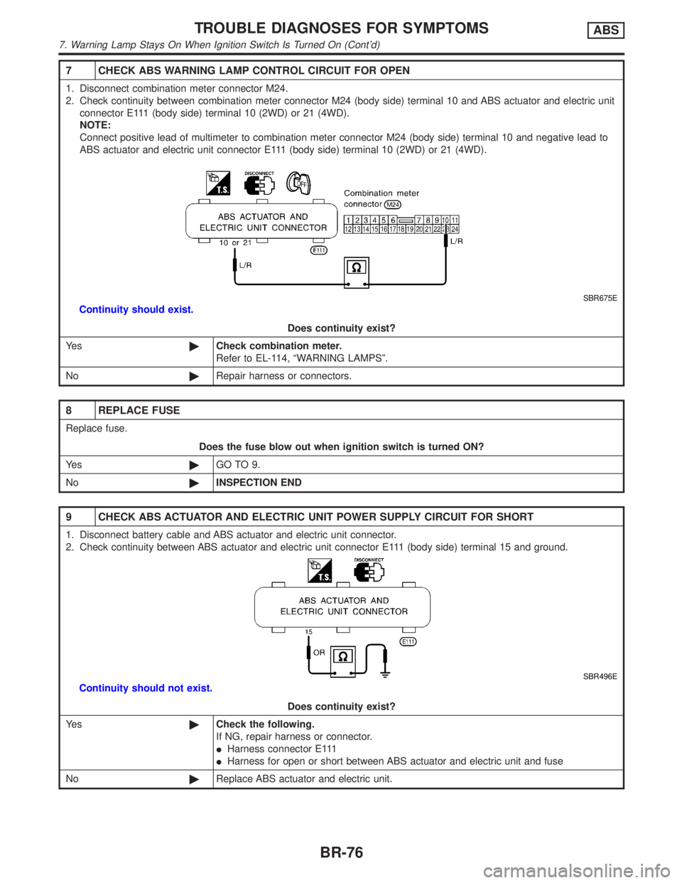
7 CHECK ABS WARNING LAMP CONTROL CIRCUIT FOR OPEN
1. Disconnect combination meter connector M24.
2. Check continuity between combination meter connector M24 (body side) terminal 10 and ABS actuator and electric unit
connector E111 (body side) terminal 10 (2WD) or 21 (4WD).
NOTE:
Connect positive lead of multimeter to combination meter connector M24 (body side) terminal 10 and negative lead to
ABS actuator and electric unit connector E111 (body side) terminal 10 (2WD) or 21 (4WD).
SBR675E
Continuity should exist.
Does continuity exist?
Ye s©Check combination meter.
Refer to EL-114, ªWARNING LAMPSº.
No©Repair harness or connectors.
8 REPLACE FUSE
Replace fuse.
Does the fuse blow out when ignition switch is turned ON?
Ye s©GO TO 9.
No©INSPECTION END
9 CHECK ABS ACTUATOR AND ELECTRIC UNIT POWER SUPPLY CIRCUIT FOR SHORT
1. Disconnect battery cable and ABS actuator and electric unit connector.
2. Check continuity between ABS actuator and electric unit connector E111 (body side) terminal 15 and ground.
SBR496E
Continuity should not exist.
Does continuity exist?
Ye s©Check the following.
If NG, repair harness or connector.
IHarness connector E111
IHarness for open or short between ABS actuator and electric unit and fuse
No©Replace ABS actuator and electric unit.
TROUBLE DIAGNOSES FOR SYMPTOMSABS
7. Warning Lamp Stays On When Ignition Switch Is Turned On (Cont'd)
BR-76
Page 472 of 2395

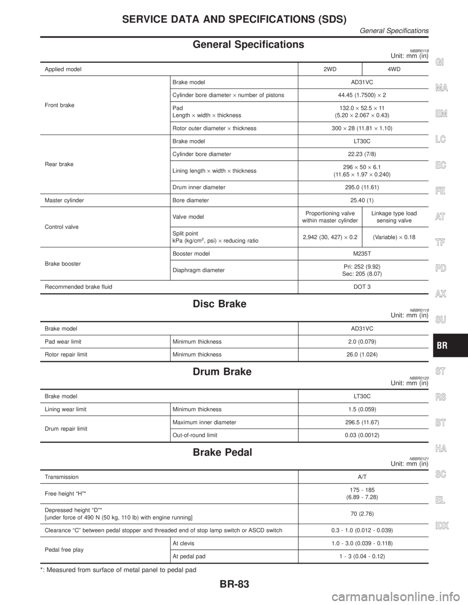
General SpecificationsNBBR0118Unit: mm (in)
Applied model2WD 4WD
Front brakeBrake model AD31VC
Cylinder bore diameter´number of pistons 44.45 (1.7500)´2
Pad
Length´width´thickness132.0´52.5´11
(5.20´2.067´0.43)
Rotor outer diameter´thickness 300´28 (11.81´1.10)
Rear brakeBrake model LT30C
Cylinder bore diameter 22.23 (7/8)
Lining length´width´thickness296´50´6.1
(11.65´1.97´0.240)
Drum inner diameter 295.0 (11.61)
Master cylinder Bore diameter 25.40 (1)
Control valveValve modelProportioning valve
within master cylinderLinkage type load
sensing valve
Split point
kPa (kg/cm
2, psi)´reducing ratio2,942 (30, 427)´0.2 (Variable)´0.18
Brake boosterBooster model M235T
Diaphragm diameterPri: 252 (9.92)
Sec: 205 (8.07)
Recommended brake fluidDOT 3
Disc BrakeNBBR0119Unit: mm (in)
Brake modelAD31VC
Pad wear limit Minimum thickness 2.0 (0.079)
Rotor repair limit Minimum thickness 26.0 (1.024)
Drum BrakeNBBR0120Unit: mm (in)
Brake modelLT30C
Lining wear limit Minimum thickness 1.5 (0.059)
Drum repair limitMaximum inner diameter 296.5 (11.67)
Out-of-round limit 0.03 (0.0012)
Brake PedalNBBR0121Unit: mm (in)
TransmissionA/T
Free height ªHº*175 - 185
(6.89 - 7.28)
Depressed height ªDº*
[under force of 490 N (50 kg, 110 lb) with engine running]70 (2.76)
Clearance ªCº between pedal stopper and threaded end of stop lamp switch or ASCD switch 0.3 - 1.0 (0.012 - 0.039)
Pedal free playAt clevis 1.0 - 3.0 (0.039 - 0.118)
At pedal pad1 - 3 (0.04 - 0.12)
*: Measured from surface of metal panel to pedal pad
GI
MA
EM
LC
EC
FE
AT
TF
PD
AX
SU
ST
RS
BT
HA
SC
EL
IDX
SERVICE DATA AND SPECIFICATIONS (SDS)
General Specifications
BR-83