Page 2200 of 2395
in high-pressure connector. Take care to install the proper
O-ring.
SST616C
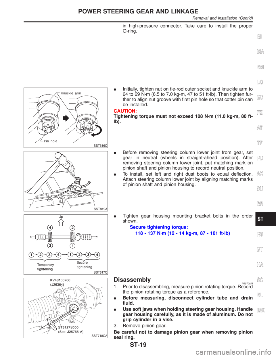
IInitially, tighten nut on tie-rod outer socket and knuckle arm to
64 to 69 N´m (6.5 to 7.0 kg-m, 47 to 51 ft-lb). Then tighten fur-
ther to align nut groove with first pin hole so that cotter pin can
be installed.
CAUTION:
Tightening torque must not exceed 108 N´m (11.0 kg-m, 80 ft-
lb).
SST819A
IBefore removing steering column lower joint from gear, set
gear in neutral (wheels in straight-ahead position). After
removing steering column lower joint, put matching mark on
pinion shaft and pinion housing to record neutral position.
ITo install, set left and right dust boots to equal deflection.
Attach steering column lower joint by aligning matching marks
of pinion shaft and pinion housing.
SST617C
ITighten gear housing mounting bracket bolts in the order
shown.
Secure tightening torque:
118 - 137 N´m (12 - 14 kg-m, 87 - 101 ft-lb)
SST718CA
DisassemblyNBST00281. Prior to disassembling, measure pinion rotating torque. Record
the pinion rotating torque as a reference.
IBefore measuring, disconnect cylinder tube and drain
fluid.
IUse soft jaws when holding steering gear housing. Handle
gear housing carefully, as it is made of aluminum. Do not
grip cylinder in a vise.
2. Remove pinion gear.
Be careful not to damage pinion gear when removing pinion
seal ring.
GI
MA
EM
LC
EC
FE
AT
TF
PD
AX
SU
BR
RS
BT
HA
SC
EL
IDX
POWER STEERING GEAR AND LINKAGE
Removal and Installation (Cont'd)
ST-19
Page 2212 of 2395
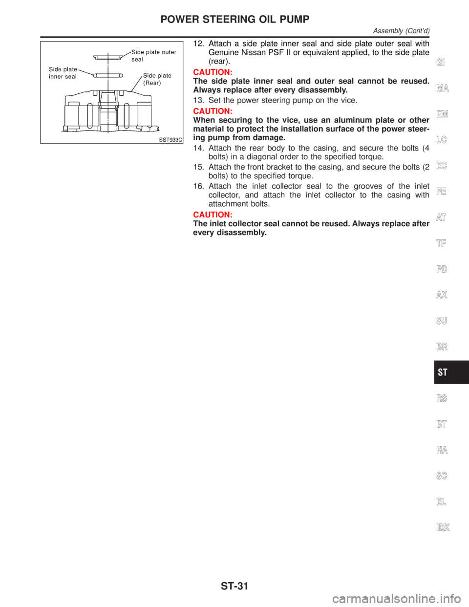
SST933C
12. Attach a side plate inner seal and side plate outer seal with
Genuine Nissan PSF II or equivalent applied, to the side plate
(rear).
CAUTION:
The side plate inner seal and outer seal cannot be reused.
Always replace after every disassembly.
13. Set the power steering pump on the vice.
CAUTION:
When securing to the vice, use an aluminum plate or other
material to protect the installation surface of the power steer-
ing pump from damage.
14. Attach the rear body to the casing, and secure the bolts (4
bolts) in a diagonal order to the specified torque.
15. Attach the front bracket to the casing, and secure the bolts (2
bolts) to the specified torque.
16. Attach the inlet collector seal to the grooves of the inlet
collector, and attach the inlet collector to the casing with
attachment bolts.
CAUTION:
The inlet collector seal cannot be reused. Always replace after
every disassembly.
GI
MA
EM
LC
EC
FE
AT
TF
PD
AX
SU
BR
RS
BT
HA
SC
EL
IDX
POWER STEERING OIL PUMP
Assembly (Cont'd)
ST-31
Page 2216 of 2395
FRONT & REAR SUSPENSION
SECTION
SU
CONTENTS
FRONT SUSPENSION....................................................2
Precautions ..................................................................2
PRECAUTIONS.........................................................2
Preparation ..................................................................2
SPECIAL SERVICE TOOLS........................................2
COMMERCIAL SERVICE TOOLS................................2
Noise, Vibration and Harshness (NVH)
Troubleshooting ...........................................................3
NVH TROUBLESHOOTING CHART............................3
Components.................................................................4
On-vehicle Service.......................................................5
FRONT SUSPENSION PARTS...................................5
FRONT WHEEL ALIGNMENT.....................................6
Coil Spring and Strut Assembly...................................8
COMPONENTS.........................................................8
REMOVAL.................................................................9
DISASSEMBLY..........................................................9
INSPECTION.............................................................9
ASSEMBLY.............................................................10
Stabilizer Bar .............................................................10
REMOVAL AND INSTALLATION...............................10
INSPECTION........................................................... 11
Transverse Link and Lower Ball Joint ....................... 11
REMOVAL AND INSTALLATION............................... 11
INSPECTION...........................................................12
Service Data and Specifications (SDS).....................13
GENERAL SPECIFICATIONS (FRONT).....................13
WHEEL ALIGNMENT (UNLADEN*1)..........................13
LOWER BALL JOINT...............................................13
WHEELARCH HEIGHT (UNLADEN*).........................14
WHEEL RUNOUT AVERAGE*..................................14
REAR SUSPENSION.....................................................15
Precautions ................................................................15
PRECAUTIONS.......................................................15
Preparation ................................................................15
COMMERCIAL SERVICE TOOLS..............................15
Noise, Vibration and Harshness (NVH)
Troubleshooting .........................................................15
Components...............................................................16
On-vehicle Service.....................................................16
REAR SUSPENSION PARTS...................................16
Removal and Installation ...........................................17
Coil Spring and Shock Absorber ...............................18
COMPONENTS.......................................................18
REMOVAL AND INSTALLATION...............................19
INSPECTION...........................................................19
Upper Link, Lower Link and Panhard Rod ................19
INSPECTION...........................................................19
BUSHING REPLACEMENT.......................................19
INSTALLATION........................................................20
Stabilizer Bar .............................................................20
REMOVAL AND INSTALLATION...............................20
Service Data and Specifications (SDS).....................20
GENERAL SPECIFICATIONS (REAR).......................20
GI
MA
EM
LC
EC
FE
AT
TF
PD
AX
BR
ST
RS
BT
HA
SC
EL
IDX
Page 2218 of 2395
Noise, Vibration and Harshness (NVH)
Troubleshooting
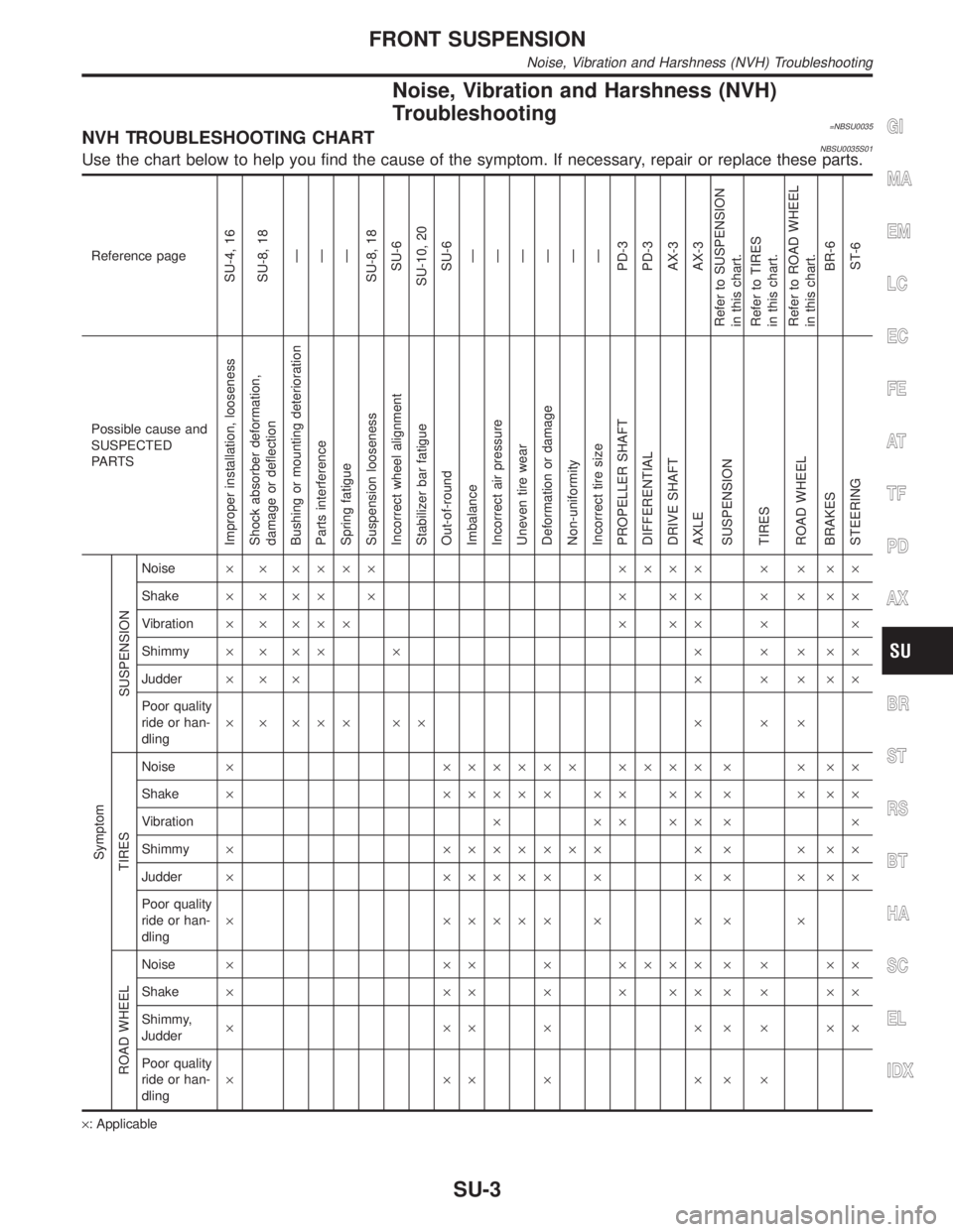
=NBSU0035NVH TROUBLESHOOTING CHARTNBSU0035S01Use the chart below to help you find the cause of the symptom. If necessary, repair or replace these parts.
Reference page
SU-4, 16
SU-8, 18
Ð
Ð
Ð
SU-8, 18
SU-6
SU-10, 20
SU-6
Ð
Ð
Ð
Ð
Ð
Ð
PD-3
PD-3
AX-3
AX-3
Refer to SUSPENSION
in this chart.
Refer to TIRES
in this chart.
Refer to ROAD WHEEL
in this chart.
BR-6
ST-6
Possible cause and
SUSPECTED
PA R T S
Improper installation, looseness
Shock absorber deformation,
damage or deflection
Bushing or mounting deterioration
Parts interference
Spring fatigue
Suspension looseness
Incorrect wheel alignment
Stabilizer bar fatigue
Out-of-round
Imbalance
Incorrect air pressure
Uneven tire wear
Deformation or damage
Non-uniformity
Incorrect tire size
PROPELLER SHAFT
DIFFERENTIAL
DRIVE SHAFT
AXLE
SUSPENSION
TIRES
ROAD WHEEL
BRAKES
STEERING Symptom
SUSPENSION
Noise´ ´ ´´´´ ´´´´ ´ ´ ´´
Shake´´´´´ ´´´ ´´´´
Vibration´ ´ ´´´ ´ ´´ ´ ´
Shimmy´´´´ ´ ´ ´ ´´´
Judder´´´ ´ ´ ´´´
Poor quality
ride or han-
dling´ ´ ´´´ ´´ ´ ´ ´
TIRES
Noise´ ´´´´´´ ´´´´ ´ ´ ´´
Shake´ ´´´´´ ´´ ´´ ´ ´ ´´
Vibration´´´´´´ ´
Shimmy´ ´´´´´´´ ´ ´ ´ ´´
Judder´ ´´´´´ ´ ´ ´ ´ ´´
Poor quality
ride or han-
dling´ ´´´´´ ´ ´ ´ ´
ROAD WHEEL
Noise´ ´´ ´ ´´´´ ´ ´ ´´
Shake´ ´´ ´ ´ ´´ ´ ´ ´´
Shimmy,
Judder´´´´´´´´´
Poor quality
ride or han-
dling´´´´´´´
´: Applicable
GI
MA
EM
LC
EC
FE
AT
TF
PD
AX
BR
ST
RS
BT
HA
SC
EL
IDX
FRONT SUSPENSION
Noise, Vibration and Harshness (NVH) Troubleshooting
SU-3
Page 2225 of 2395
SFA725B
ASSEMBLYNBSU0011IWhen installing coil spring on strut, it must be positioned as
shown in the figure at left.
SFA664AA
IInstall upper spring seat with its cutout facing the inner side of
vehicle.
SFA767B
Stabilizer Bar
REMOVAL AND INSTALLATIONNBSU0012IRemove stabilizer bar and connecting rod.
SFA768B
IWhen installing stabilizer, make sure that paint mark and
bracket face in their correct directions.
SFA769B
IWhen removing and installing stabilizer bar fix portion A.
FRONT SUSPENSION
Coil Spring and Strut Assembly (Cont'd)
SU-10
Page 2226 of 2395
SFA449BA
IInstall stabilizer bar with ball joint socket properly placed.
ARA027
INSPECTIONNBSU0013ICheck stabilizer for deformation and cracks. Replace if neces-
sary.
ICheck rubber bushings for deterioration and cracks. Replace
if necessary.
ICheck ball joint can rotate in all directions. If movement is not
smooth and free, replace stabilizer bar connecting rod.
SFA757B
Transverse Link and Lower Ball Joint
REMOVAL AND INSTALLATIONNBSU00141. Separate drive shaft from knuckle.
Refer to AX-10, ªDrive Shaftº.
2. Separate lower ball joint stud from knuckle.
3. Remove lower ball joint assembly from transverse link.
4. Remove transverse link.
5. During installation, final tightening must be carried out at curb
weight with tires on ground.
6. After installation, check wheel alignment.
Refer to ªFRONT WHEEL ALIGNMENTº, ªOn-vehicle Serviceº,
SU-6.
GI
MA
EM
LC
EC
FE
AT
TF
PD
AX
BR
ST
RS
BT
HA
SC
EL
IDX
FRONT SUSPENSION
Stabilizer Bar (Cont'd)
SU-11
Page 2232 of 2395
SBR686C
Removal and InstallationNBSU00261. Support axle and suspension components with a suitable jack
and block.
2. Disconnect brake hydraulic line and parking brake cables at
back plates.
CAUTION:
IUse flare nut wrench when removing and installing brake
tubes.
IBefore removing the rear suspension assembly, discon-
nect the ABS wheel sensor from the assembly. Then move
it away from the rear suspension assembly. Failure to do
so may result in damage to the sensor wires and the sen-
sor becoming inoperative.
3. Remove stabilizer bar from body.
4. Remove upper links and lower links from body.
5. Remove panhard rod from body.
6. Disconnect rear end of propeller shaft. Refer to PD-6,
ªRemoval and Installationº.
7. Remove upper end nuts of shock absorber.
SRA935
Final tightening for rubber parts requires to be carried out
under unladen condition with tires on ground.
GI
MA
EM
LC
EC
FE
AT
TF
PD
AX
BR
ST
RS
BT
HA
SC
EL
IDX
REAR SUSPENSION
Removal and Installation
SU-17
Page 2234 of 2395
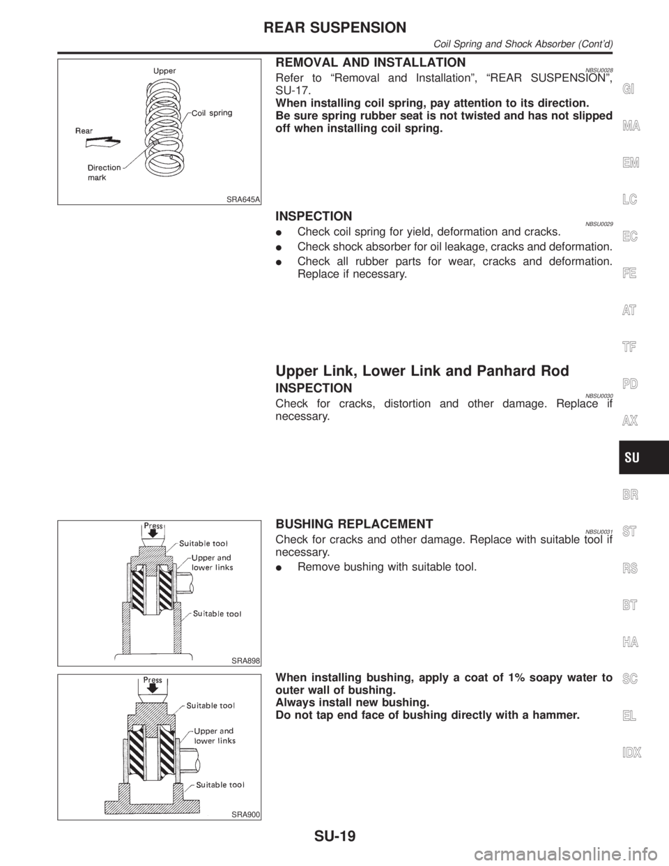
SRA645A
REMOVAL AND INSTALLATIONNBSU0028Refer to ªRemoval and Installationº, ªREAR SUSPENSIONº,
SU-17.
When installing coil spring, pay attention to its direction.
Be sure spring rubber seat is not twisted and has not slipped
off when installing coil spring.
INSPECTIONNBSU0029ICheck coil spring for yield, deformation and cracks.
ICheck shock absorber for oil leakage, cracks and deformation.
ICheck all rubber parts for wear, cracks and deformation.
Replace if necessary.
Upper Link, Lower Link and Panhard Rod
INSPECTIONNBSU0030Check for cracks, distortion and other damage. Replace if
necessary.
SRA898
BUSHING REPLACEMENTNBSU0031Check for cracks and other damage. Replace with suitable tool if
necessary.
IRemove bushing with suitable tool.
SRA900
When installing bushing, apply a coat of 1% soapy water to
outer wall of bushing.
Always install new bushing.
Do not tap end face of bushing directly with a hammer.
GI
MA
EM
LC
EC
FE
AT
TF
PD
AX
BR
ST
RS
BT
HA
SC
EL
IDX
REAR SUSPENSION
Coil Spring and Shock Absorber (Cont'd)
SU-19