2001 INFINITI QX4 INSTALLATION
[x] Cancel search: INSTALLATIONPage 2183 of 2395
Supplemental Restraint System (SRS) ªAIR
BAGº and ªSEAT BELT PRE-TENSIONERº
NBST0044The Supplemental Restraint System such as ªAIR BAGº and ªSEAT BELT PRE-TENSIONERº used along with
a seat belt, helps to reduce the risk or severity of injury to the driver and front passenger for certain types of
collision. The SRS system composition which is available to INFINITI QX4 is as follows:
IFor a frontal collision
The Supplemental Restraint System consists of driver air bag module (located in the center of the steer-
ing wheel), front passenger air bag module (located on the instrument panel on passenger side), seat belt
pre-tensioners, a diagnosis sensor unit, warning lamp, wiring harness and spiral cable.
IFor a side collision
The Supplemental Restraint System consists of side air bag module (located in the outer side of front seat),
satellite sensor, diagnosis sensor unit (one of components of air bags for a frontal collision), wiring harness,
warning lamp (one of components of air bags for a frontal collision).
Information necessary to service the system safely is included in theRS sectionof this Service Manual.
WARNING:
ITo avoid rendering the SRS inoperative, which could increase the risk of personal injury or death
in the event of a collision which would result in air bag inflation, all maintenance must be performed
by an authorized INFINITI dealer.
IImproper maintenance, including incorrect removal and installation of the SRS, can lead to per-
sonal injury caused by unintentional activation of the system. For removal of Spiral Cable and Air
Bag Module, see the RS section.
IDo not use electrical test equipment on any circuit related to the SRS unless instructed to in this
Service Manual. Spiral cable and wiring harnesses covered with yellow insulation tape either just
before the harness connectors or for the complete harness are related to the SRS.
Precautions for Steering SystemNBST0002IBefore disassembly, thoroughly clean the outside of the unit.
IDisassembly should be done in a clean work area. It is important to prevent the internal parts from
becoming contaminated by dirt or other foreign matter.
IPlace disassembled parts in order, on a parts rack, for easier and proper assembly.
IUse nylon cloths or paper towels to clean the parts; common shop rags can leave lint that might
interfere with their operation.
IBefore inspection or reassembly, carefully clean all parts with a general purpose, non-flammable
solvent.
IBefore assembly, apply a coat of recommended power steering fluid* to hydraulic parts. Vaseline
may be applied to O-rings and seals. Do not use any grease.
IReplace all gaskets, seals and O-rings. Avoid damaging O-rings, seals and gaskets during instal-
lation. Perform functional tests whenever designated.
*: Genuine Nissan PSF II or equivalent. Refer to MA-11, ªFluids and Lubricantsº.
PRECAUTIONS
Supplemental Restraint System (SRS) ªAIR BAGº and ªSEAT BELT PRE-TENSIONERº
ST-2
Page 2187 of 2395
NBST0043
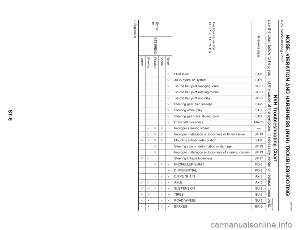
NVH Troubleshooting ChartNBST0043S01Use the chart below to help you find the cause of the symptom. If necessary, repair or replace these parts.
Reference pageST-8
ST-9
ST-21
ST-21
ST-21
ST-8
ST-7
ST-9
MA-13
Ð
ST-13
ST-8
ST-13
ST-13
ST-17
PD-3
PD-3
AX-3
AX-3
SU-3
SU-3
SU-3
BR-6
Possible cause and
SUSPECTED PARTS
Fluid level
Air in hydraulic system
Tie-rod ball joint swinging force
Tie-rod ball joint rotating torque
Tie-rod ball joint end play
Steering gear fluid leakage
Steering wheel play
Steering gear rack sliding force
Drive belt looseness
Improper steering wheel
Improper installation or looseness or tilt lock lever
Mounting rubber deterioration
Steering column deformation or damage
Improper installation or looseness of steering column
Steering linkage looseness
PROPELLER SHAFT
DIFFERENTIAL
DRIVE SHAFT
AXLE
SUSPENSION
TIRES
ROAD WHEEL
BRAKES
Symp-
tomSTEERINGNoise´´´´´´´´´ ´´´´´´´´
Shake´´´ ´ ´´´´´´
Vibration´´´´´ ´ ´´´´
Shimmy´´´ ´ ´´´´´
Judder´ ´ ´´´´´
´: Applicable
NOISE, VIBRATION AND HARSHNESS (NVH) TROUBLESHOOTING
NVH Troubleshooting Chart
ST-6
Page 2189 of 2395
SST601C
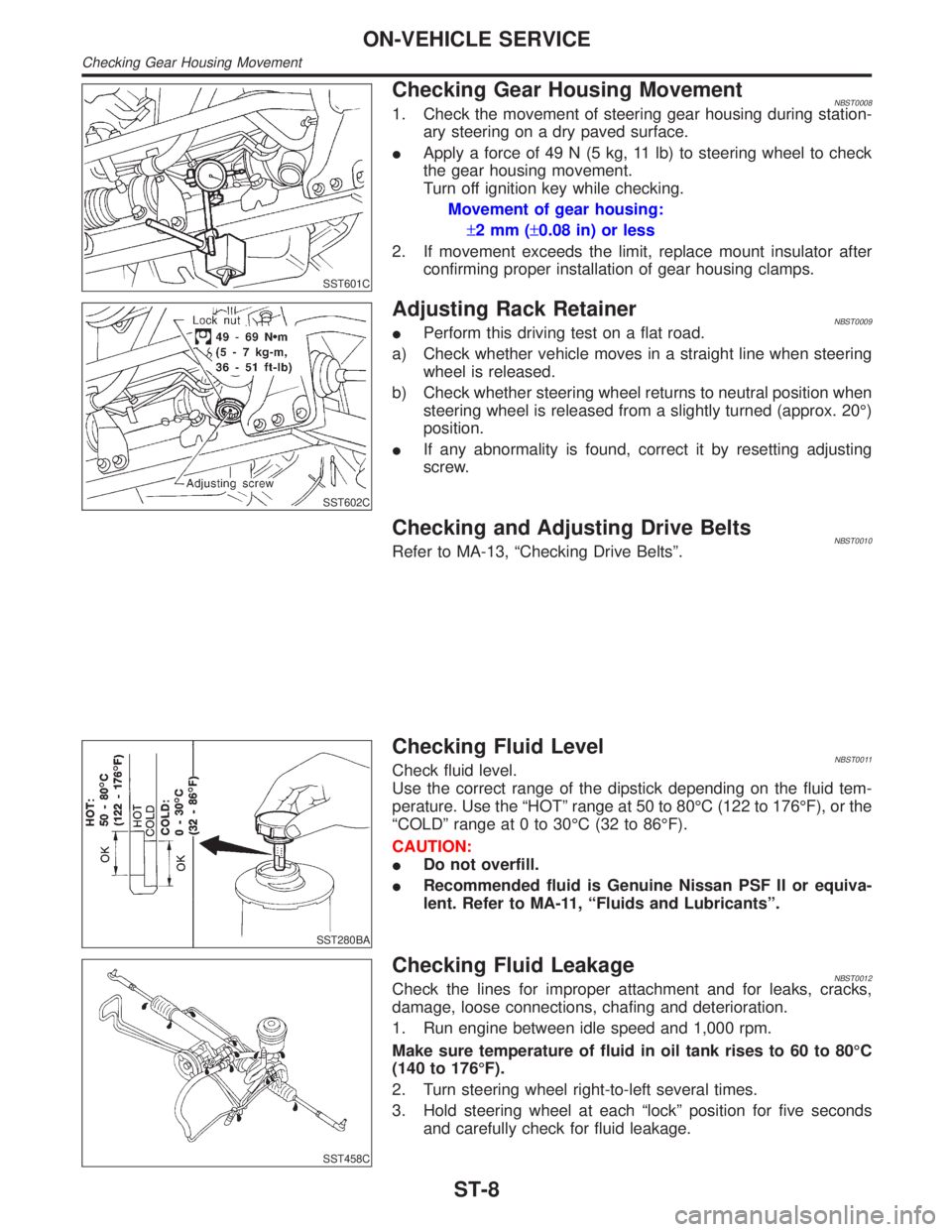
Checking Gear Housing MovementNBST00081. Check the movement of steering gear housing during station-
ary steering on a dry paved surface.
IApply a force of 49 N (5 kg, 11 lb) to steering wheel to check
the gear housing movement.
Turn off ignition key while checking.
Movement of gear housing:
±2mm(±0.08 in) or less
2. If movement exceeds the limit, replace mount insulator after
confirming proper installation of gear housing clamps.
SST602C
Adjusting Rack RetainerNBST0009IPerform this driving test on a flat road.
a) Check whether vehicle moves in a straight line when steering
wheel is released.
b) Check whether steering wheel returns to neutral position when
steering wheel is released from a slightly turned (approx. 20É)
position.
IIf any abnormality is found, correct it by resetting adjusting
screw.
Checking and Adjusting Drive BeltsNBST0010Refer to MA-13, ªChecking Drive Beltsº.
SST280BA
Checking Fluid LevelNBST0011Check fluid level.
Use the correct range of the dipstick depending on the fluid tem-
perature. Use the ªHOTº range at 50 to 80ÉC (122 to 176ÉF), or the
ªCOLDº range at 0 to 30ÉC (32 to 86ÉF).
CAUTION:
IDo not overfill.
IRecommended fluid is Genuine Nissan PSF II or equiva-
lent. Refer to MA-11, ªFluids and Lubricantsº.
SST458C
Checking Fluid LeakageNBST0012Check the lines for improper attachment and for leaks, cracks,
damage, loose connections, chafing and deterioration.
1. Run engine between idle speed and 1,000 rpm.
Make sure temperature of fluid in oil tank rises to 60 to 80ÉC
(140 to 176ÉF).
2. Turn steering wheel right-to-left several times.
3. Hold steering wheel at each ªlockº position for five seconds
and carefully check for fluid leakage.
ON-VEHICLE SERVICE
Checking Gear Housing Movement
ST-8
Page 2191 of 2395
6. If rack sliding force is not within specification, overhaul steer-
ing gear assembly.
7. If rack sliding force is OK, inspect steering column. Refer to
ªInspectionº, ªSTEERING WHEEL AND STEERING
COLUMNº, ST-14.
SST834-F
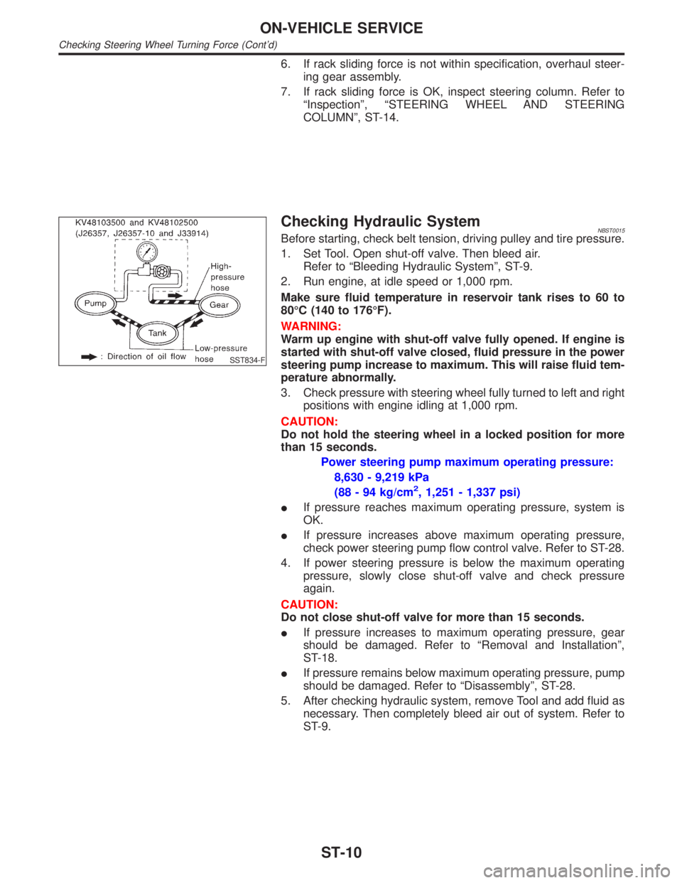
Checking Hydraulic SystemNBST0015Before starting, check belt tension, driving pulley and tire pressure.
1. Set Tool. Open shut-off valve. Then bleed air.
Refer to ªBleeding Hydraulic Systemº, ST-9.
2. Run engine, at idle speed or 1,000 rpm.
Make sure fluid temperature in reservoir tank rises to 60 to
80ÉC (140 to 176ÉF).
WARNING:
Warm up engine with shut-off valve fully opened. If engine is
started with shut-off valve closed, fluid pressure in the power
steering pump increase to maximum. This will raise fluid tem-
perature abnormally.
3. Check pressure with steering wheel fully turned to left and right
positions with engine idling at 1,000 rpm.
CAUTION:
Do not hold the steering wheel in a locked position for more
than 15 seconds.
Power steering pump maximum operating pressure:
8,630 - 9,219 kPa
(88 - 94 kg/cm
2, 1,251 - 1,337 psi)
IIf pressure reaches maximum operating pressure, system is
OK.
IIf pressure increases above maximum operating pressure,
check power steering pump flow control valve. Refer to ST-28.
4. If power steering pressure is below the maximum operating
pressure, slowly close shut-off valve and check pressure
again.
CAUTION:
Do not close shut-off valve for more than 15 seconds.
IIf pressure increases to maximum operating pressure, gear
should be damaged. Refer to ªRemoval and Installationº,
ST-18.
IIf pressure remains below maximum operating pressure, pump
should be damaged. Refer to ªDisassemblyº, ST-28.
5. After checking hydraulic system, remove Tool and add fluid as
necessary. Then completely bleed air out of system. Refer to
ST-9.
ON-VEHICLE SERVICE
Checking Steering Wheel Turning Force (Cont'd)
ST-10
Page 2192 of 2395
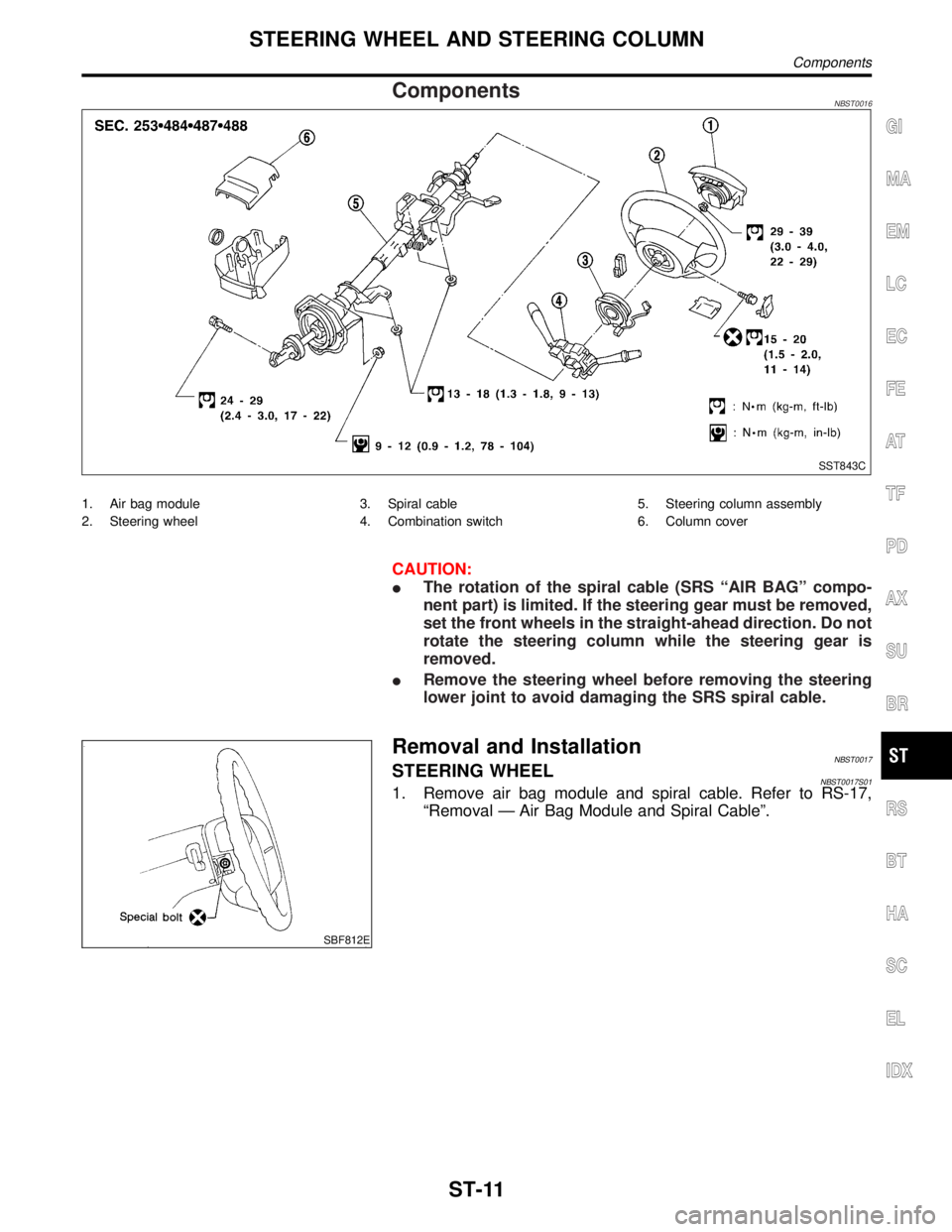
ComponentsNBST0016
SST843C
1. Air bag module
2. Steering wheel3. Spiral cable
4. Combination switch5. Steering column assembly
6. Column cover
CAUTION:
IThe rotation of the spiral cable (SRS ªAIR BAGº compo-
nent part) is limited. If the steering gear must be removed,
set the front wheels in the straight-ahead direction. Do not
rotate the steering column while the steering gear is
removed.
IRemove the steering wheel before removing the steering
lower joint to avoid damaging the SRS spiral cable.
SBF812E
Removal and InstallationNBST0017STEERING WHEELNBST0017S011. Remove air bag module and spiral cable. Refer to RS-17,
ªRemoval Ð Air Bag Module and Spiral Cableº.
GI
MA
EM
LC
EC
FE
AT
TF
PD
AX
SU
BR
RS
BT
HA
SC
EL
IDX
STEERING WHEEL AND STEERING COLUMN
Components
ST-11
Page 2193 of 2395
SRS266
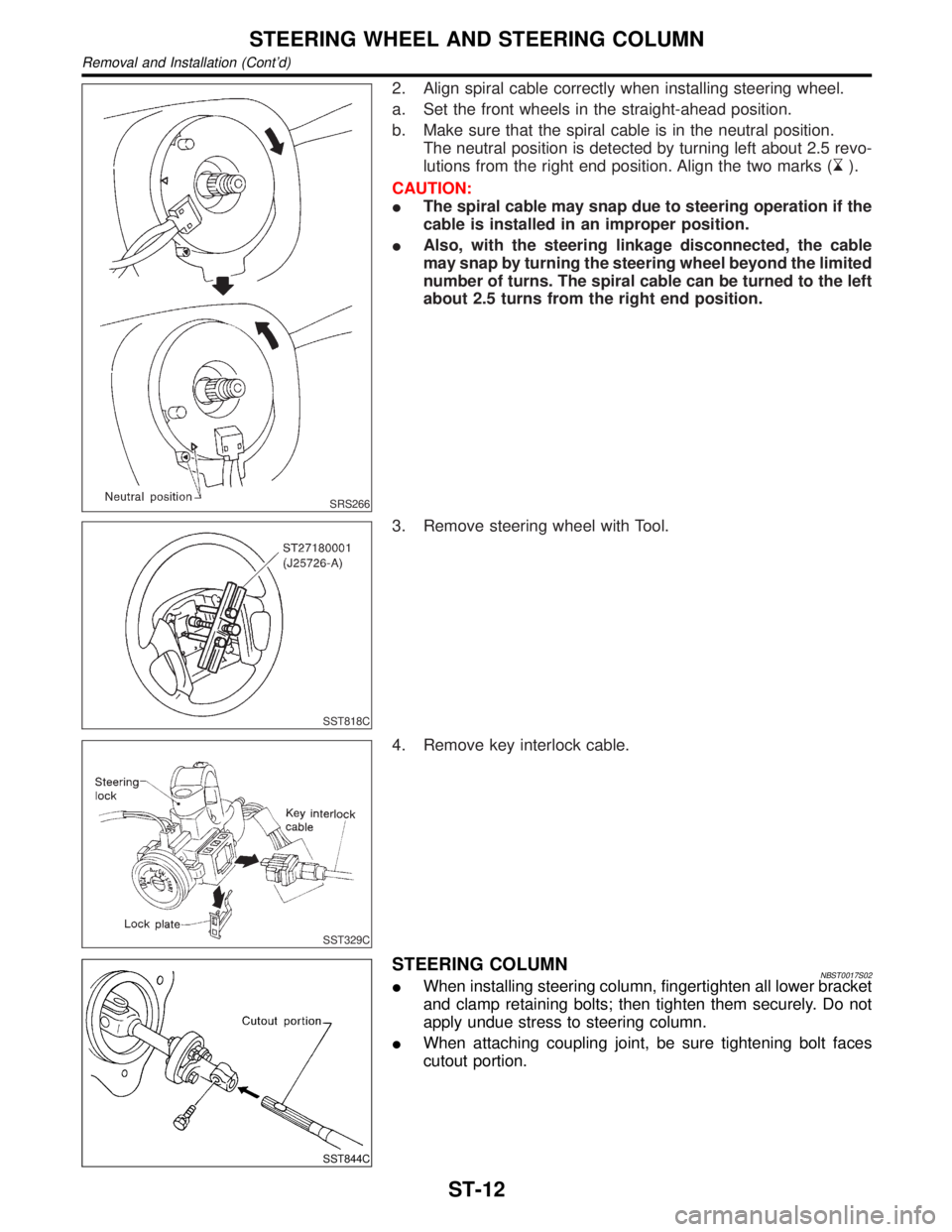
2. Align spiral cable correctly when installing steering wheel.
a. Set the front wheels in the straight-ahead position.
b. Make sure that the spiral cable is in the neutral position.
The neutral position is detected by turning left about 2.5 revo-
lutions from the right end position. Align the two marks (
).
CAUTION:
IThe spiral cable may snap due to steering operation if the
cable is installed in an improper position.
IAlso, with the steering linkage disconnected, the cable
may snap by turning the steering wheel beyond the limited
number of turns. The spiral cable can be turned to the left
about 2.5 turns from the right end position.
SST818C
3. Remove steering wheel with Tool.
SST329C
4. Remove key interlock cable.
SST844C
STEERING COLUMNNBST0017S02IWhen installing steering column, fingertighten all lower bracket
and clamp retaining bolts; then tighten them securely. Do not
apply undue stress to steering column.
IWhen attaching coupling joint, be sure tightening bolt faces
cutout portion.
STEERING WHEEL AND STEERING COLUMN
Removal and Installation (Cont'd)
ST-12
Page 2197 of 2395
SST847C
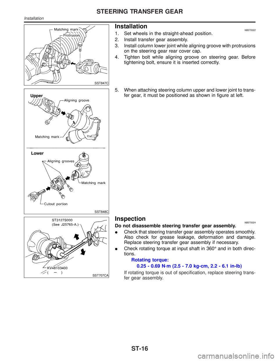
InstallationNBST00221. Set wheels in the straight-ahead position.
2. Install transfer gear assembly.
3. Install column lower joint while aligning groove with protrusions
on the steering gear rear cover cap.
4. Tighten bolt while aligning groove on steering gear. Before
tightening bolt, ensure it is inserted correctly.
SST848C
5. When attaching steering column upper and lower joint to trans-
fer gear, it must be positioned as shown in figure at left.
SST707CA
InspectionNBST0024Do not disassemble steering transfer gear assembly.
ICheck that steering transfer gear assembly operates smoothly.
Also check for grease leakage, deformation and damage.
Replace steering transfer gear assembly if necessary.
ICheck rotating torque at input shaft in 360É and in both direc-
tions.
Rotating torque:
0.25 - 0.69 N´m (2.5 - 7.0 kg-cm, 2.2 - 6.1 in-lb)
If rotating torque is out of specification, replace steering trans-
fer gear assembly.
STEERING TRANSFER GEAR
Installation
ST-16
Page 2199 of 2395
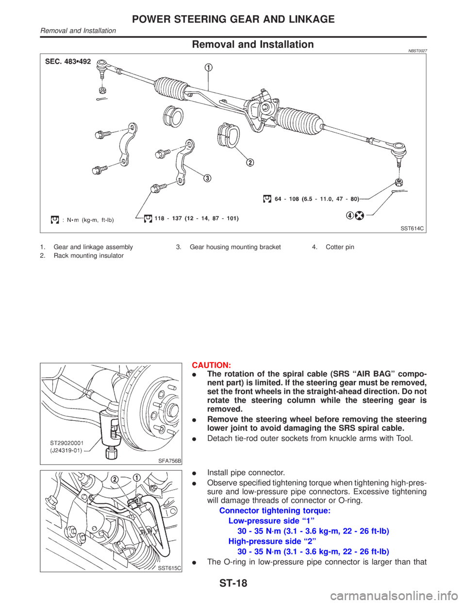
Removal and InstallationNBST0027
SST614C
1. Gear and linkage assembly
2. Rack mounting insulator3. Gear housing mounting bracket 4. Cotter pin
SFA756B
CAUTION:
IThe rotation of the spiral cable (SRS ªAIR BAGº compo-
nent part) is limited. If the steering gear must be removed,
set the front wheels in the straight-ahead direction. Do not
rotate the steering column while the steering gear is
removed.
IRemove the steering wheel before removing the steering
lower joint to avoid damaging the SRS spiral cable.
IDetach tie-rod outer sockets from knuckle arms with Tool.
SST615C
IInstall pipe connector.
IObserve specified tightening torque when tightening high-pres-
sure and low-pressure pipe connectors. Excessive tightening
will damage threads of connector or O-ring.
Connector tightening torque:
Low-pressure side ª1º
30 - 35 N´m (3.1 - 3.6 kg-m, 22 - 26 ft-lb)
High-pressure side ª2º
30 - 35 N´m (3.1 - 3.6 kg-m, 22 - 26 ft-lb)
IThe O-ring in low-pressure pipe connector is larger than that
POWER STEERING GEAR AND LINKAGE
Removal and Installation
ST-18