Page 1336 of 2395

Component Parts and Harness Connector
Location
NBEL0072
SEL465X
System DescriptionNBEL0073The rear window defogger system is controlled by the smart entrance control unit. The rear window defogger
operates only for approximately 15 minutes.
Power is supplied at all times
Ito rear window defogger relay terminal 3
Ithrough 20A fuse (No. 56, located in the fuse and fusible link box) and
Ito rear window defogger relay terminal 6
Ithrough 20A fuse (No. 57, located in the fuse and fusible link box)
Ito smart entrance control unit terminal 10
Ithrough 7.5A [No. 24, located in fuse block (J/B)]
With the ignition switch in the ON or START position, power is supplied
Ithrough 7.5A fuse [No. 11, located in the fuse block (J/B)]
Ito the rear window defogger relay terminal 1, and
Ito smart entrance control unit terminal 33.
Ground is supplied
Ito terminal 1 of the rear window defogger switch
Ithrough body grounds M4, M66 and M147(with navigation system),
Ito terminal 32 of the A/C auto amp.
Ithrough body grounds M4, M66 and M147 (without navigation system), or
Ito smart entrance control unit terminal 16
Ithrough body grounds M77 and M111.
GI
MA
EM
LC
EC
FE
AT
TF
PD
AX
SU
BR
ST
RS
BT
HA
SC
IDX
REAR WINDOW DEFOGGER
Component Parts and Harness Connector Location
EL-151
Page 1340 of 2395

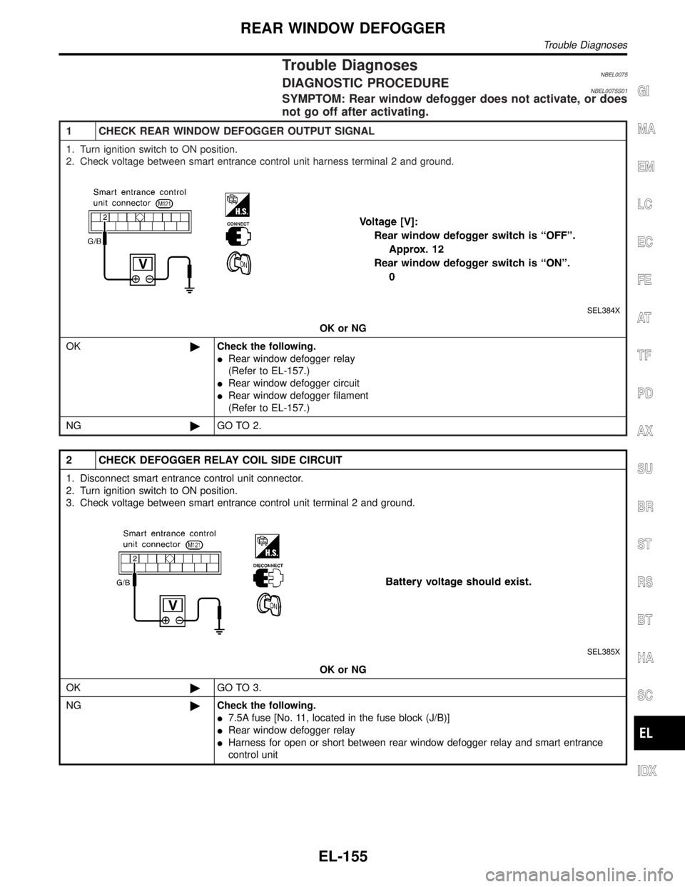
Trouble DiagnosesNBEL0075DIAGNOSTIC PROCEDURENBEL0075S01SYMPTOM: Rear window defogger does not activate, or does
not go off after activating.
1 CHECK REAR WINDOW DEFOGGER OUTPUT SIGNAL
1. Turn ignition switch to ON position.
2. Check voltage between smart entrance control unit harness terminal 2 and ground.
SEL384X
OK or NG
OK©Check the following.
IRear window defogger relay
(Refer to EL-157.)
IRear window defogger circuit
IRear window defogger filament
(Refer to EL-157.)
NG©GO TO 2.
2 CHECK DEFOGGER RELAY COIL SIDE CIRCUIT
1. Disconnect smart entrance control unit connector.
2. Turn ignition switch to ON position.
3. Check voltage between smart entrance control unit terminal 2 and ground.
SEL385X
OK or NG
OK©GO TO 3.
NG©Check the following.
I7.5A fuse [No. 11, located in the fuse block (J/B)]
IRear window defogger relay
IHarness for open or short between rear window defogger relay and smart entrance
control unit
GI
MA
EM
LC
EC
FE
AT
TF
PD
AX
SU
BR
ST
RS
BT
HA
SC
IDX
REAR WINDOW DEFOGGER
Trouble Diagnoses
EL-155
Page 1341 of 2395
3 CHECK REAR WINDOW DEFOGGER SWITCH INPUT SIGNAL
Check continuity between smart entrance control unit terminal 39 and ground.
SEL386X
OK or NG
OK©GO TO 4.
NG©Check the following.
IRear window defogger switch (with navigation system)
(Refer to EL-157.)
IA/C auto amp. (without navigation system)
IHarness for open or short between smart entrance control unit and rear window defog-
ger switch (with navigation system) or A/C auto amp. (without navigation system)
IRear window defogger switch (with navigation system) or A/C auto amp. (without navi-
gation system) ground circuit
4 CHECK IGNITION INPUT SIGNAL
Check voltage between smart entrance control unit terminal 33 and ground.
SEL387X
OK or NG
OK©GO TO 5.
NG©Check the following.
I7.5A fuse [No. 11, located in the fuse block (J/B)]
IHarness for open or short between smart entrance control unit and fuse
REAR WINDOW DEFOGGER
Trouble Diagnoses (Cont'd)
EL-156
Page 1387 of 2395
SEL601W
DIAGNOSTIC PROCEDURE 1=NBEL0214S04(Power supply and ground circuit for driver's seat control unit)
Power Supply Circuit CheckNBEL0214S0401Check voltage between seat control unit LH terminal 1 and ground.
TerminalsIgnition switch position
OFF ACC ON START
1 - Ground Battery voltage
If NG, check the following.
I40A fusible link (letterf, located in the fuse and fusible link box)
ICircuit breaker
IHarness for open or short between circuit breaker and seat
control unit LH
SEL602W
Ground Circuit CheckNBEL0214S0402Check continuity between seat control unit LH terminal 33 and
ground.
Terminals Continuity
33 - Ground Yes
AUTOMATIC DRIVE POSITIONER
Trouble Diagnoses (Cont'd)
EL-202
Page 1402 of 2395
DIAGNOSTIC PROCEDURE 12=NBEL0214S15(Key, detention, door switch and vehicle speed sensor check)
1 CHECK KEY SWITCH INPUT SIGNAL
Check voltage between seat control unit LH terminal 2 and ground.
SEL629W
OK or NG
OK©GO TO 2.
NG©Check the following.
I7.5A fuse [No. 24, located in fuse block (J/B)]
IKey switch
IHarness for open or short between key switch and fuse
IHarness for open or short between seat control unit LH and key switch
2 CHECK IGNITION SWITCH INPUT SIGNAL (ON AND START)
Check voltage between seat control unit LH terminals and ground.
SEL630W
OK or NG
OK©GO TO 3.
NG©Check the following.
I7.5A fuse [No. 11, located in fuse block (J/B)]
I7.5A fuse [No. 26, located in fuse block (J/B)]
IHarness for open or short between seat control unit LH and fuse
GI
MA
EM
LC
EC
FE
AT
TF
PD
AX
SU
BR
ST
RS
BT
HA
SC
IDX
AUTOMATIC DRIVE POSITIONER
Trouble Diagnoses (Cont'd)
EL-217
Page 1404 of 2395
6 CHECK VEHICLE SPEED SENSOR PULL UP VOLTAGE
1. Turn ignition switch ªONº.
2. Check voltage between seat control unit LH terminal 32 and ground.
SEL633W
OK or NG
OK©Harness for open or short between seat control unit LH and combination meter.
NG©Repair harness.
GI
MA
EM
LC
EC
FE
AT
TF
PD
AX
SU
BR
ST
RS
BT
HA
SC
IDX
AUTOMATIC DRIVE POSITIONER
Trouble Diagnoses (Cont'd)
EL-219
Page 1417 of 2395
POWER SUPPLY AND GROUND CIRCUIT CHECK=NBEL0218S03
1 CHECK POWER SUPPLY CIRCUIT FOR ASCD CONTROL UNIT
1. Disconnect ASCD control unit harness connector.
2. Turn ignition switch ON.
3. Check voltage between ASCD control unit harness connector terminal 5 and ground.
SEL256WB
Refer to wiring diagram in EL-227.
Ye s©GO TO 2.
No©Check the following.
I7.5A fuse (No. 11 located in the fuse block)
IHarness for open or short
2 CHECK GROUND CIRCUIT FOR ASCD CONTROL UNIT
Check continuity between ASCD control unit harness connector terminal 17 and body ground.
SEL257WB
Refer to wiring diagram in EL-227.
Ye s©Power supply and ground circuit is OK.
No©Repair harness.
AUTOMATIC SPEED CONTROL DEVICE (ASCD)
Trouble Diagnoses (Cont'd)
EL-232
Page 1418 of 2395

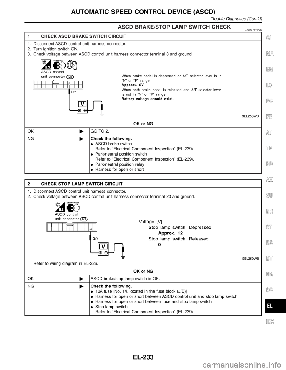
ASCD BRAKE/STOP LAMP SWITCH CHECK=NBEL0218S04
1 CHECK ASCD BRAKE SWITCH CIRCUIT
1. Disconnect ASCD control unit harness connector.
2. Turn ignition switch ON.
3. Check voltage between ASCD control unit harness connector terminal 8 and ground.
SEL258WD
OK or NG
OK©GO TO 2.
NG©Check the following.
IASCD brake switch
Refer to ªElectrical Component Inspectionº (EL-239).
IPark/neutral position switch
Refer to ªElectrical Component Inspectionº (EL-239).
IPark/neutral position relay
IHarness for open or short
2 CHECK STOP LAMP SWITCH CIRCUIT
1. Disconnect ASCD control unit harness connector.
2. Check voltage between ASCD control unit harness connector terminal 23 and ground.
SEL259WB
Refer to wiring diagram in EL-226.
OK or NG
OK©ASCD brake/stop lamp switch is OK.
NG©Check the following.
I10A fuse [No. 14, located in the fuse block (J/B)]
IHarness for open or short between ASCD control unit and stop lamp switch
IHarness for open or short between fuse and stop lamp switch
IStop lamp switch
Refer to ªElectrical Component Inspectionº (EL-239).
GI
MA
EM
LC
EC
FE
AT
TF
PD
AX
SU
BR
ST
RS
BT
HA
SC
IDX
AUTOMATIC SPEED CONTROL DEVICE (ASCD)
Trouble Diagnoses (Cont'd)
EL-233