2001 INFINITI QX4 air condition
[x] Cancel search: air conditionPage 1961 of 2395
A
AAC/V - Wiring diagram ...............................EC-425
ABS - Wiring diagram ....................................BR-37
ABS sensor rotor ........................................AX-6, 19
Absolute pressure sensor ............................EC-158
A/C air flow .....................................................HA-25
A/C component layout ....................................HA-19
A/C compressor clutch removal and
installation .................................................HA-150
A/C compressor precaution..............................HA-6
A/C compressor special service tool..............HA-10
A/C control operation (auto A/C) ....................HA-23
A/C diagnostic work flow (auto A/C) ..............HA-65
A/C HFC134a (R134a) system
precaution .....................................................HA-2
A/C HFC134a (R134a) system service
procedure ..................................................HA-144
A/C HFC134a (R134a) system service
tools.............................................................HA-11
A/C HFC134a system service equip-
ment precaution ............................................HA-7
A/C lubricant (R134a)...................................HA-146
A/C operational check ....................................HA-66
A/C performance chart .................................HA-116
A/C performance test diagnoses ..................HA-114
A/C relay .......................................................HA-110
A/C self-diagnoses (auto A/C)........................HA-44
A/C service data specification ......................HA-160
A/C system description (auto A/C) .................HA-23
A/C trouble diagnoses (auto A/C) ..................HA-27
A/C, A - Wiring diagram ...........................HA-31, 36
Accelerator control system ...............................FE-3
Accelerator wire adjustment .............................FE-3
Actuator lever (Transfer) ...............................TF-120
Air bag ............................................................RS-10
Air bag disposal..............................................RS-22
Air bag precautions ...........................................GI-3
Air bleeding for brake system ..........................BR-8
Air cleaner filter replacement .........................MA-17
Air conditioner cut control ..............................EC-31
Air flow meter - See Mass air flow
sensor .......................................................EC-150
Air mix door control linkage adjustment.........HA-85
Air mix. door motor ................................HA-82, 141
Air spoiler, rear................................................BT-35
All - mode 4WD system ..................................TF-10
Alternator ........................................................SC-28
Ambient sensor ............................................HA-129
Angular tightening application..........................EM-3
Antenna - See Power antenna .....................EL-169
Anti-lock brake system - Wiring
diagram .......................................................BR-37
AP/SEN - Wiring diagram ............................EC-160
ASCD (automatic speed control device) ......EL-221
ASCD - Wiring diagram ................................EL-225
A/T - Wiring diagram - AT - FTS ...................AT-107
A/T - Wiring diagram - AT - MAIN ...................AT-96
A/T - Wiring diagram - AT - PNP/SW............AT-101A/T - Wiring diagram - AT - VSS A/T ............AT-113
A/T control ....................................................EC-440
A/T diagnosis communication line................EC-603
A/T fluid temperature sensor .........................AT-110
A/T self-diagnoses...........................................AT-46
A/T shift lock system .....................................AT-265
A/T shift lock system - Wiring diagram .........AT-266
A/T trouble diagnoses .....................................AT-53
A/T Wiring diagram - AT - ENG SS...............AT-117
A/T Wiring diagram AT - 1ST ........................AT-123
A/T Wiring diagram AT - 2ND .......................AT-129
A/T Wiring diagram AT - 3RD .......................AT-135
A/T Wiring diagram AT - 4TH ........................AT-142
A/T Wiring diagram AT - BA/FTS ..................AT-192
A/T Wiring diagram AT - LPSV .....................AT-164
A/T Wiring diagram AT - NONDTC ...............AT-215
A/T Wiring diagram AT - OVRCSV ...............AT-187
A/T Wiring diagram AT - SSV/A ....................AT-169
A/T Wiring diagram AT - SSV/B ....................AT-173
A/T Wiring diagram AT - TCCSIG .................AT-156
A/T Wiring diagram AT - TCV .......................AT-150
A/T Wiring diagram AT - TPS........................AT-179
A/T Wiring diagram AT - VSSMTR................AT-199
AT/C - Wiring diagram ..................................EC-442
ATP switch.....................................................TF-112
ATP warning lamp .........................................TF-102
Audio .............................................................EL-160
AUDIO - Wiring diagram ...............................EL-162
Audio and A/C control removal and
installation - See Instrument panel .............BT-21
AUT/DP - Wiring diagram .............................EL-191
Auto air conditioner - Wiring diagram ......HA-31, 36
Automatic amplifier...................................HA-40, 72
Automatic drive positioner ............................EL-186
Automatic speed control system - See
ASCD ........................................................EL-221
Automatic transmission fluid
replacement ................................................MA-21
Automatic transmission number ......................GI-43
Auxiliary air control (AAC) valve ..................EC-422
Axle housing (rear) .........................................AX-19
B
Back door ........................................................BT-15
Back door opener - See Back door ................BT-15
Back door trim.................................................BT-34
Back-up lamp ..................................................EL-69
BACK/L - Wiring diagram................................EL-69
Ball joint (front) ...............................................SU-12
Base idle air volume initialiging......................EC-57
Basic inspection ...........................................EC-101
Battery ..............................................................SC-4
Battery/Starting/Charging System
Tester ................................................SC-7, 12, 21
Blower motor ..................................................HA-95
Body alignment ...............................................BT-57
Brake booster .................................................BR-19
Brake control valve (Proportioning
valve)...........................................................BR-11
ALPHABETICAL INDEX
IDX-2
Page 1999 of 2395

NBMA0003
General maintenance includes those items which should be checked during the normal day-to-day operation
of the vehicle. They are essential if the vehicle is to continue operating properly. The owners can perform
checks and inspections themselves or they can have their INFINITI dealers do them.
OUTSIDE THE VEHICLE
The maintenance items listed here should be performed from time to time, unless otherwise specified.
ItemReference page
TiresCheck the pressure with a gauge periodically when at a service station,
including the spare, and adjust to the specified pressure if necessary. Check
carefully for damage, cuts or excessive wear.Ð
Wheel nutsWhen checking the tires, make sure no nuts are missing, and check for any
loose nuts. Tighten if necessary.Ð
Tire rotationTires should be rotated every 12,000 km (7,500 miles). MA-24
Wheel alignment and
balanceIf the vehicle pulls to either side while driving on a straight and level road, or
if you detect uneven or abnormal tire wear, there may be a need for wheel
alignment. If the steering wheel or seat vibrates at normal highway speeds,
wheel balancing may be needed.MA-24, SU-6, ªFront
Wheel Alignmentº
Windshield wiper
bladesCheck for cracks or wear if they do not wipe properly. Ð
Doors and engine
hoodCheck that all doors and the engine hood operate smoothly as well as the
trunk lid and back hatch. Also make sure that all latches lock securely. Lubri-
cate if necessary. Make sure that the secondary latch keeps the hood from
opening when the primary latch is released.
When driving in areas using road salt or other corrosive materials, check
lubrication frequently.MA-27
INSIDE THE VEHICLE
The maintenance items listed here should be checked on a regular basis, such as when performing periodic maintenance, cleaning the
vehicle, etc.
ItemReference page
LampsMake sure that the headlamps, stop lamps, tail lamps, turn signal lamps, and
other lamps are all operating properly and installed securely. Also check
headlamp aim.Ð
Warning lamps and
buzzers/chimesMake sure that all warning lamps and buzzers/chimes are operating properly. Ð
Windshield wiper
and washerCheck that the wipers and washer operate properly and that the wipers do
not streak.Ð
Windshield defrosterCheck that the air comes out of the defroster outlets properly and in sufficient
quantity when operating the heater or air conditioning.Ð
Steering wheelCheck that it has the specified play. Be sure to check for changes in the
steering condition, such as excessive play, hard steering or strange noises.
Free play: Less than 35 mm (1.38 in)Ð
SeatsCheck seat position controls such as seat adjusters, seatback recliner, etc. to
make sure they operate smoothly and that all latches lock securely in every
position. Check that the head restrains move up and down smoothly and that
the locks (if equipped) hold securely in all latched positions. Check that the
latches lock securely for folding-down rear seatbacks.Ð
Seat beltsCheck that all parts of the seat belt system (e.g. buckles, anchors, adjusters
and retractors) operate properly and smoothly and are installed securely.
Check the belt webbing for cuts, fraying, wear or damage.MA-28, RS-7, ªSeat Belt
Inspectionº
BrakesCheck that the brake does not pull the vehicle to one side when applied. Ð
GENERAL MAINTENANCE
MA-4
Page 2000 of 2395
ItemReference page
Brake pedal and
boosterCheck the pedal for smooth operation and make sure it has the proper dis-
tance under it when depressed fully. Check the brake booster function. Be
sure to keep floor mats away from the pedal.BR-14, ªBrake Pedal and
Bracketº and BR-19,
ªBrake Boosterº
Parking brakeCheck that the lever has the proper travel and make sure that the vehicle is
held securely on a fairly steep hill when only the parking brake is applied.BR-31, ªParking Brake
Controlº
Automatic transmis-
sion ªParkº mecha-
nismCheck that the lock release button on the selector lever operates properly
and smoothly. On a fairly steep hill check that the vehicle is held securely
with the selector lever in the ªPº position without applying any brakes.Ð
UNDER THE HOOD AND VEHICLE
The maintenance items listed here should be checked periodically (e.g. each time you check the engine oil or refuel).
ItemReference page
Windshield washer
fluidCheck that there is adequate fluid in the tank. Ð
Engine coolant levelCheck the coolant level when the engine is cold. MA-15
Radiator and hosesCheck the front of the radiator and clean off any dirt, insects, leaves, etc.,
that may have accumulated. Make sure the hoses have no cracks,
deformation, deterioration or loose connections.Ð
Brake fluid levelsMake sure that the brake fluid levels are between the ªMAXº and ªMINº lines
on the reservoir.MA-25
BatteryCheck the fluid level in each cell. It should be between the ªMAXº and ªMINº
lines.Ð
Engine drive beltsMake sure that no belt is frayed, worn, cracked or oily. MA-13
Engine oil levelCheck the level on the dipstick after parking the vehicle on a level spot and
turning off the engine.MA-18
Power steering fluid
level and linesCheck the level on the dipstick with the engine off. Check the lines for
improper attachment, leaks, cracks, etc.MA-27
Automatic transmis-
sion fluid levelCheck the level on the dipstick after putting the selector lever in ªPº with the
engine idling.MA-21
Exhaust systemMake sure there are no loose supports, cracks or holes. If the sound of the
exhaust seems unusual or there is a smell of exhaust fumes, immediately
locate the trouble and correct it.MA-21
UnderbodyThe underbody is frequently exposed to corrosive substances such as those
used on icy roads or to control dust. It is very important to remove these
substances, otherwise rust will form on the floor pan, frame, fuel lines and
around the exhaust system. At the end of winter, the underbody should be
thoroughly flushed with plain water, being careful to clean those areas where
mud and dirt can easily accumulate.Ð
Fluid leaksCheck under the vehicle for fuel, oil, water or other fluid leaks after the
vehicle has been parked for a while. Water dripping from the air conditioner
after use is normal. If you should notice any leaks or gasoline fumes are
evident, check for the cause and correct it immediately.Ð
GI
EM
LC
EC
FE
AT
TF
PD
AX
SU
BR
ST
RS
BT
HA
SC
EL
IDX
GENERAL MAINTENANCE
MA-5
Page 2001 of 2395
NBMA0004
Two different maintenance schedules are provided, and should be used, depending upon the conditions in
which the vehicle is mainly operated.After 60,000 miles (96,000 km) or 48 months, continue the periodic
maintenance at the same mileage/time intervals.
Schedule 1Follow Periodic Maintenance Schedule 1 if your driving habits frequently
includes one or more of the following driving conditions:
IRepeated short trips of less than 5 miles (8 km).
IRepeated short trips of less than 10 miles (16 km) with outside tempera-
tures remaining below freezing.
IOperating in hot weather in stop-and-go ªrush hourº traffic.
IExtensive idling and/or low speed driving for long distances, such as police,
taxi or door-to-door delivery use.
IDriving in dusty conditions.
IDriving on rough, muddy, or salt spread roads.
ITowing a trailer, using a camper or a car-top carrier.Emission Control Sys-
tem Maintenance
MA-7
Chassis and Body
Maintenance
MA-8
Schedule 2Follow Periodic Maintenance Schedule 2 if none of the driving conditions
shown in Schedule 1 apply to your driving habits.Emission Control Sys-
tem MaintenanceMA-9
Chassis and Body
MaintenanceMA-10
Maintenance for off-road driving
Whenever you drive off-road through sand, mud or water, more frequent maintenance may be required of the
following items:
GBrake pads and rotors
GBrake lining and drums
GBrake lines and hoses
GWheel bearing grease
GDifferential, transmission and transfer oil
GSteering linkage
GPropeller shaft and drive shafts
GAir cleaner filter
PERIODIC MAINTENANCE
MA-6
Page 2002 of 2395
![INFINITI QX4 2001 Factory Service Manual Schedule 1NBMA0004S01EMISSION CONTROL SYSTEM MAINTENANCENBMA0004S0101
Abbreviations: R = Replace. I = Inspect. Correct or replace if necessary. [ ]: At the mileage intervals only
MAINTENANCE OPERATION INFINITI QX4 2001 Factory Service Manual Schedule 1NBMA0004S01EMISSION CONTROL SYSTEM MAINTENANCENBMA0004S0101
Abbreviations: R = Replace. I = Inspect. Correct or replace if necessary. [ ]: At the mileage intervals only
MAINTENANCE OPERATION](/manual-img/42/57027/w960_57027-2001.png)
Schedule 1NBMA0004S01EMISSION CONTROL SYSTEM MAINTENANCENBMA0004S0101
Abbreviations: R = Replace. I = Inspect. Correct or replace if necessary. [ ]: At the mileage intervals only
MAINTENANCE OPERATIONMAINTENANCE INTERVAL
Reference
Section
- Page or
- Content Title Perform at number of miles, kilo-
meters or months, whichever
comes first.Miles x 1,000
(km x 1,000)
Months3.75
(6)
37.5
(12)
611.25
(18)
915
(24)
1218.75
(30)
1522.5
(36)
1826.25
(42)
2130
(48)
2433.75
(54)
2737.5
(60)
3041.25
(66)
3345
(72)
3648.75
(78)
3952.5
(84)
4256.25
(90)
4560
(96)
48
Drive beltsI* I* MA-13
Air cleaner filter NOTE (1) [R] [R] MA-17
EVAP vapor linesI* I* MA-20
Fuel linesI* I* MA-16
Fuel filter* NOTE (2)MA-16
Engine coolant NOTE (3)R* MA-14
Engine oil RRRRRRRRRRRRRRRRMA-18
Engine oil filter (Use part No.
15208-31U00 or equivalent.)RRRRRRRRRRRRRRRRMA-18
Spark plugs (PLATINUM-TIPPED
type)Replace every 105,000 miles (169,000 km) MA-19
Intake & exhaust valve clearance* NOTE (4)EM-52, ªValve
Clearanceº
NOTE:
(1) If operating mainly in dusty conditions, more frequent maintenance may be required.
(2) When the filter becomes clogged, the vehicle speed cannot be increased as the driver wishes. In such an event, replace the filter.
(3) After 60,000 miles (96,000 km) or 48 months, replace every 30,000 miles (48,000 km) or 24 months.
(4) If valve noise increases, inspect valve clearance.
HMaintenance items and intervals with ª*º are recommended by INFINITI for reliable vehicle operation. The owner need not perform such maintenance in order to maintain the
emission warranty or manufacturer recall liability. Other maintenance items and intervals are required.
GI
EM
LC
EC
FE
AT
TF
PD
AX
SU
BR
ST
RS
BT
HA
SC
EL
IDX
PERIODIC MAINTENANCE
Schedule 1
MA-7
Page 2008 of 2395

Checking Drive BeltsNBMA0010
SMA091D
1. Inspect belt for cracks, fraying, wear and oil. If necessary,
replace.
2. Inspect drive belt deflection or tension at a point on the belt
midway between pulleys.
3. Check belt tension using belt tension gauge (BT3373-F or
equivalent).
Inspect drive belt deflection or tension when engine is cold.
Adjust if belt deflections exceed the limit or if belt tension is
not within specifications.
Belt deflection and tension
Deflection adjustment Unit: mm (in) Tension adjustment *1 Unit: N (kg, lb)
Used belt
New beltUsed belt
New belt
Limit After adjustment Limit After adjustment
Alternator
Power steering
oil pump
Fan7 (0.28)4-5
(0.16 - 0.20)3.5 - 4.5
(0.138 - 0.177)294 (30, 66)730 - 818 (74.4 -
83.5, 164 - 184)838 - 926 (85.4 -
94.5, 188 - 208)
Air conditioner
compressor12 (0.47)9-10
(0.35 - 0.39)8-9
(0.31 - 0.35)196 (20, 44)348 - 436 (35.5 -
44.5, 78 - 98)470 - 559 (47.9 -
57.0, 106 - 126)
Applied pushing
force98 N (10 kg, 22 lb) Ð
*1 If belt tension gauge cannot be installed at check points shown, check drive belt tension at a different location on the belt.
GI
EM
LC
EC
FE
AT
TF
PD
AX
SU
BR
ST
RS
BT
HA
SC
EL
IDX
ENGINE MAINTENANCE
Checking Drive Belts
MA-13
Page 2009 of 2395
SMA857C
SMA858C
Changing Engine CoolantNBMA0011WARNING:
To avoid the danger of being scalded, never change the cool-
ant when the engine is hot.
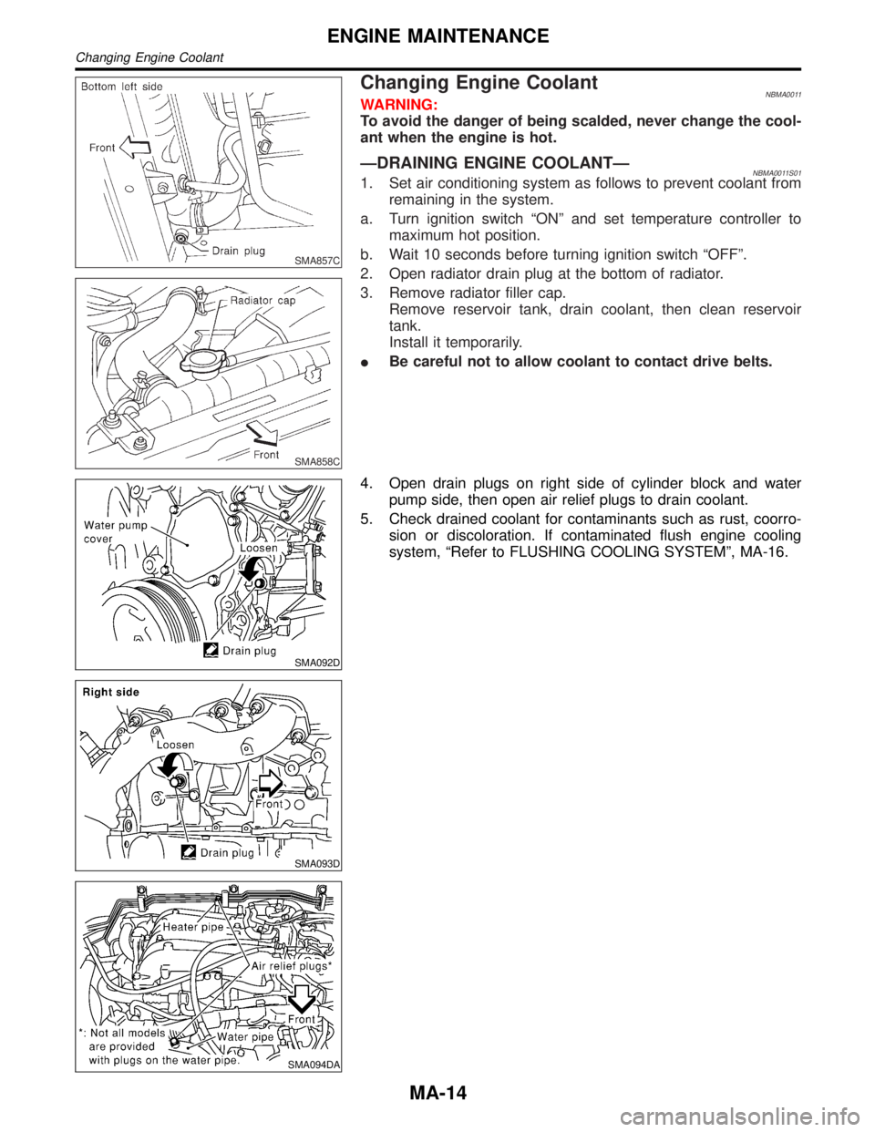
ÐDRAINING ENGINE COOLANTÐNBMA0011S011. Set air conditioning system as follows to prevent coolant from
remaining in the system.
a. Turn ignition switch ªONº and set temperature controller to
maximum hot position.
b. Wait 10 seconds before turning ignition switch ªOFFº.
2. Open radiator drain plug at the bottom of radiator.
3. Remove radiator filler cap.
Remove reservoir tank, drain coolant, then clean reservoir
tank.
Install it temporarily.
IBe careful not to allow coolant to contact drive belts.
SMA092D
SMA093D
SMA094DA
4. Open drain plugs on right side of cylinder block and water
pump side, then open air relief plugs to drain coolant.
5. Check drained coolant for contaminants such as rust, coorro-
sion or discoloration. If contaminated flush engine cooling
system, ªRefer to FLUSHING COOLING SYSTEMº, MA-16.
ENGINE MAINTENANCE
Changing Engine Coolant
MA-14
Page 2015 of 2395
: 20 - 29 N´m (2.0 - 3.0 kg-m, 14 - 22 ft-lb)
Use standard type spark plug for normal condition.
The hot type spark plug is suitable when fouling may occur with the
standard type spark plug such as:
Ifrequent engine starts
Ilow ambient temperatures
The cold type spark plug is suitable when spark knock may occur
with the standard type spark plug such as:
Iextended highway driving
Ifrequent high engine revolution
SMA773C
IDo not use a wire brush for cleaning.
IIf plug tip is covered with carbon, spark plug cleaner may
be used.
Cleaner air pressure:
Less than 588 kPa (6 kg/cm
2, 85 psi)
Cleaning time:
Less than 20 seconds
SMA806C
IChecking and adjusting plug gap is not required between
change intervals.
SMA099D
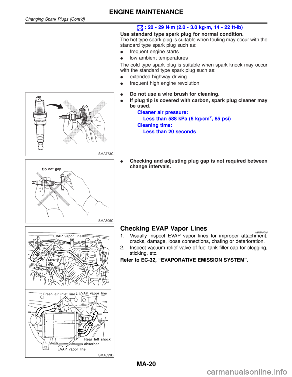
Checking EVAP Vapor LinesNBMA00181. Visually inspect EVAP vapor lines for improper attachment,
cracks, damage, loose connections, chafing or deterioration.
2. Inspect vacuum relief valve of fuel tank filler cap for clogging,
sticking, etc.
Refer to EC-32, ªEVAPORATIVE EMISSION SYSTEMº.
ENGINE MAINTENANCE
Changing Spark Plugs (Cont'd)
MA-20