2001 INFINITI QX4 air condition
[x] Cancel search: air conditionPage 1869 of 2395

RHA463GA
RHA334HA
8. Check AUTO ModeNBHA0019S02081. Press AUTO switch.
2. Display should indicate AUTO (no ECON).
Confirm that the compressor clutch engages (audio or visual
inspection).
(Discharge air and blower speed will depend on ambient, in-
vehicle and set temperatures.)
If NG, go to trouble diagnosis procedure for A/C system (HA-71),
then if necessary, trouble diagnosis procedure for magnet clutch
(HA-104).
SHA286HA
9. Check Ambient Display (With Navigation System)NBHA0019S02091. Press AUTO switch.
2. Press AMB switch.
3. Display should show the outside (ambient) temperature for
approximately 5 seconds.
If NG, go to trouble diagnosis procedure for multiplex communica-
tion circuit (HA-142).
If all operational check are OK (symptom can not be duplicated),
go to ªIncident Simulation Testsº (GI section) and perform tests as
outlined to simulate driving conditions environment. If symptom
appears, refer to ªSymptom Tableº (HA-65) and perform applicable
trouble diagnosis procedures.
TROUBLE DIAGNOSES
Operational Check (Cont'd)
HA-70
Page 1871 of 2395

RHA464GA
RHA858H
MAIN POWER SUPPLY AND GROUND CIRCUIT CHECKNBHA0037Component DescriptionNBHA0037S01Automatic Amplifier (Auto Amp.)NBHA0037S0101The auto amplifier has a built-in microcomputer which processes
information sent from various sensors needed for air conditioner
operation. The air mix door motor, mode door motor, intake door
motor, blower motor and compressor are then controlled.
The auto amplifier is unitized with control mechanisms. Signals
from various switches and Potentio Temperature Control (PTC) are
directly entered into auto amplifier.
Self-diagnostic functions are also built into auto amplifier to provide
quick check of malfunctions in the auto air conditioner system.
RHA464GA
RHA867H
Potentio Temperature Control (PTC)NBHA0037S0102The PTC is built into the A/C auto amp. or Display & NAVI control
unit. It can be set at an interval of 0.5ÉC (1.0ÉF) in the 18ÉC (65ÉF)
to 32ÉC (85ÉF) temperature range by pushing the temperature but-
ton. The set temperature is digitally displayed.
TROUBLE DIAGNOSES
A/C System (Cont'd)
HA-72
Page 1896 of 2395
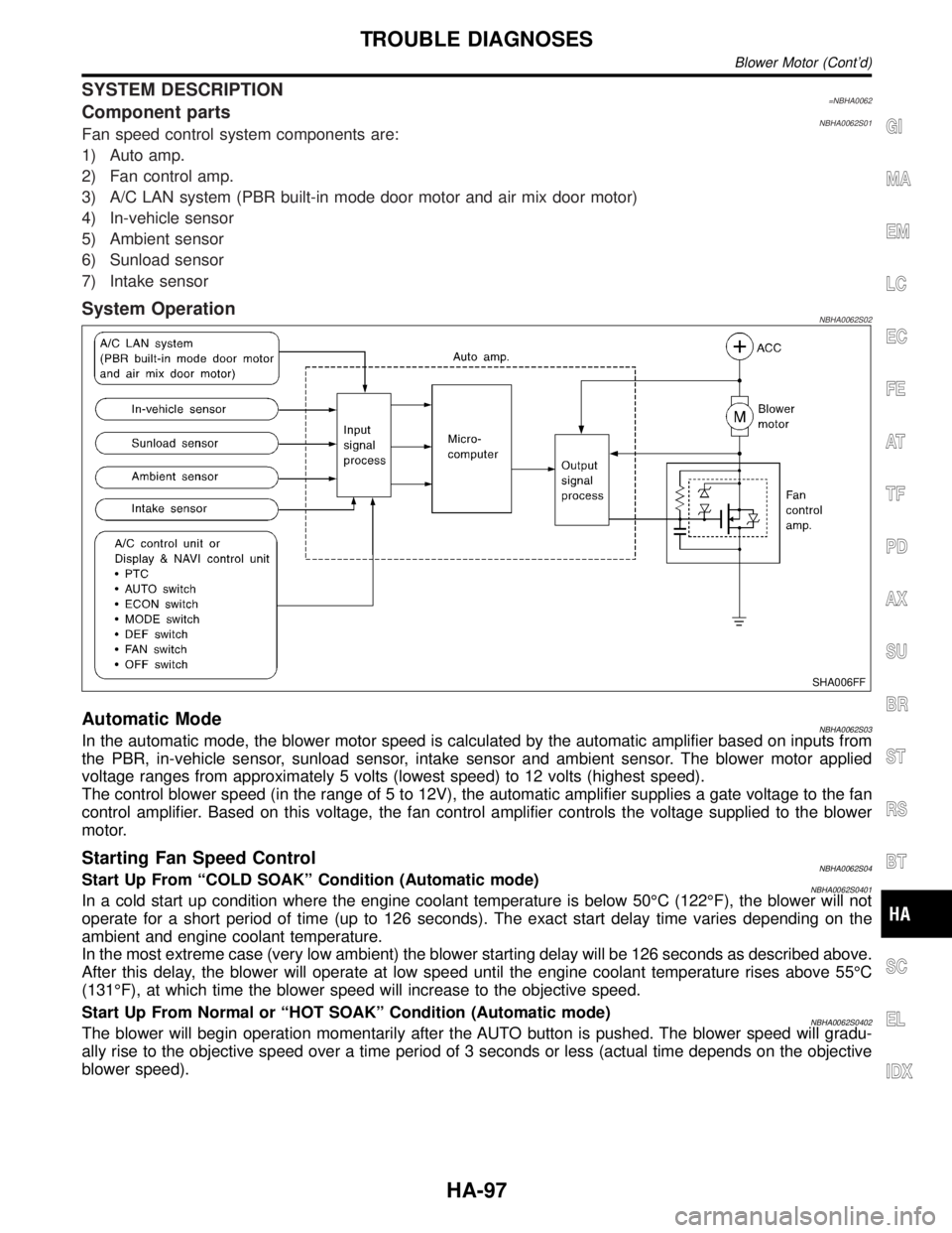
SYSTEM DESCRIPTION=NBHA0062Component partsNBHA0062S01Fan speed control system components are:
1) Auto amp.
2) Fan control amp.
3) A/C LAN system (PBR built-in mode door motor and air mix door motor)
4) In-vehicle sensor
5) Ambient sensor
6) Sunload sensor
7) Intake sensor
System OperationNBHA0062S02
SHA006FF
Automatic ModeNBHA0062S03In the automatic mode, the blower motor speed is calculated by the automatic amplifier based on inputs from
the PBR, in-vehicle sensor, sunload sensor, intake sensor and ambient sensor. The blower motor applied
voltage ranges from approximately 5 volts (lowest speed) to 12 volts (highest speed).
The control blower speed (in the range of 5 to 12V), the automatic amplifier supplies a gate voltage to the fan
control amplifier. Based on this voltage, the fan control amplifier controls the voltage supplied to the blower
motor.
Starting Fan Speed ControlNBHA0062S04Start Up From ªCOLD SOAKº Condition (Automatic mode)NBHA0062S0401In a cold start up condition where the engine coolant temperature is below 50ÉC (122ÉF), the blower will not
operate for a short period of time (up to 126 seconds). The exact start delay time varies depending on the
ambient and engine coolant temperature.
In the most extreme case (very low ambient) the blower starting delay will be 126 seconds as described above.
After this delay, the blower will operate at low speed until the engine coolant temperature rises above 55ÉC
(131ÉF), at which time the blower speed will increase to the objective speed.
Start Up From Normal or ªHOT SOAKº Condition (Automatic mode)
NBHA0062S0402The blower will begin operation momentarily after the AUTO button is pushed. The blower speed will gradu-
ally rise to the objective speed over a time period of 3 seconds or less (actual time depends on the objective
blower speed).
GI
MA
EM
LC
EC
FE
AT
TF
PD
AX
SU
BR
ST
RS
BT
SC
EL
IDX
TROUBLE DIAGNOSES
Blower Motor (Cont'd)
HA-97
Page 1909 of 2395
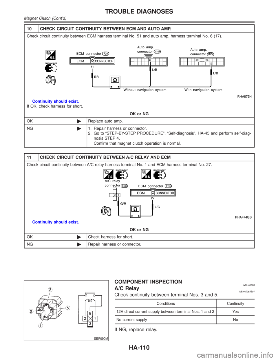
10 CHECK CIRCUIT CONTINUITY BETWEEN ECM AND AUTO AMP.
Check circuit continuity between ECM harness terminal No. 51 and auto amp. harness terminal No. 6 (17).
RHA879H
Continuity should exist.
If OK, check harness for short.
OK or NG
OK©Replace auto amp.
NG©1. Repair harness or connector.
2. Go to ªSTEP-BY-STEP PROCEDUREº, ªSelf-diagnosisº, HA-45 and perform self-diag-
nosis STEP 4.
Confirm that magnet clutch operation is normal.
11 CHECK CIRCUIT CONTINUITY BETWEEN A/C RELAY AND ECM
Check circuit continuity between A/C relay harness terminal No. 1 and ECM harness terminal No. 27.
RHA474GB
Continuity should exist.
OK or NG
OK©Check harness for short.
NG©Repair harness or connector.
SEF090M
COMPONENT INSPECTIONNBHA0068A/C RelayNBHA0068S01Check continuity between terminal Nos. 3 and 5.
Conditions Continuity
12V direct current supply between terminal Nos. 1 and 2 Yes
No current supply No
If NG, replace relay.
TROUBLE DIAGNOSES
Magnet Clutch (Cont'd)
HA-110
Page 1915 of 2395
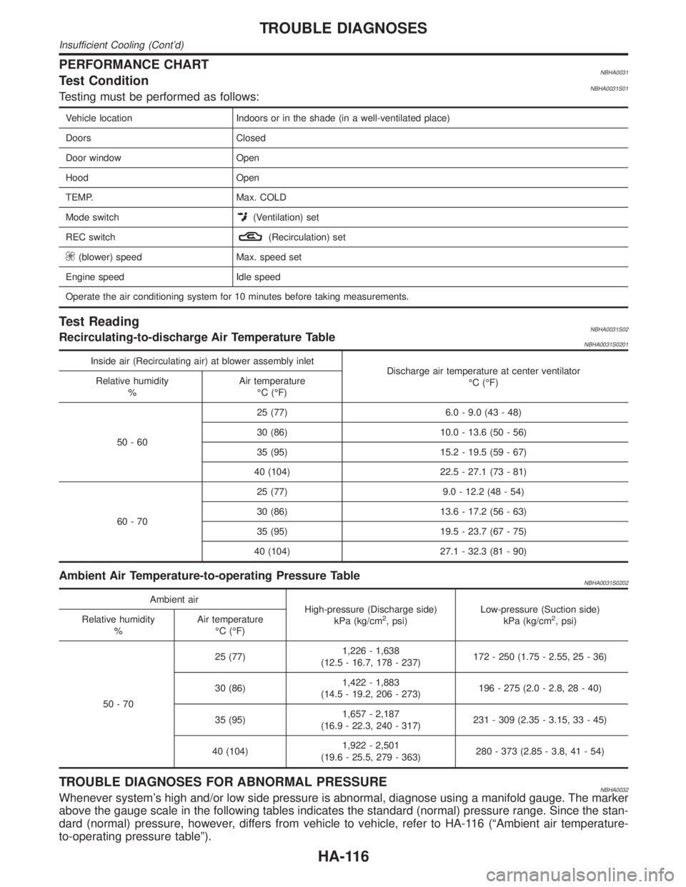
PERFORMANCE CHARTNBHA0031Test ConditionNBHA0031S01Testing must be performed as follows:
Vehicle location Indoors or in the shade (in a well-ventilated place)
Doors Closed
Door window Open
Hood Open
TEMP. Max. COLD
Mode switch
(Ventilation) set
REC switch
(Recirculation) set
(blower) speed Max. speed set
Engine speed Idle speed
Operate the air conditioning system for 10 minutes before taking measurements.
Test ReadingNBHA0031S02Recirculating-to-discharge Air Temperature TableNBHA0031S0201
Inside air (Recirculating air) at blower assembly inlet
Discharge air temperature at center ventilator
ÉC (ÉF) Relative humidity
%Air temperature
ÉC (ÉF)
50-6025 (77) 6.0 - 9.0 (43 - 48)
30 (86) 10.0 - 13.6 (50 - 56)
35 (95) 15.2 - 19.5 (59 - 67)
40 (104) 22.5 - 27.1 (73 - 81)
60-7025 (77) 9.0 - 12.2 (48 - 54)
30 (86) 13.6 - 17.2 (56 - 63)
35 (95) 19.5 - 23.7 (67 - 75)
40 (104) 27.1 - 32.3 (81 - 90)
Ambient Air Temperature-to-operating Pressure TableNBHA0031S0202
Ambient air
High-pressure (Discharge side)
kPa (kg/cm
2, psi)Low-pressure (Suction side)
kPa (kg/cm2, psi) Relative humidity
%Air temperature
ÉC (ÉF)
50-7025 (77)1,226 - 1,638
(12.5 - 16.7, 178 - 237)172 - 250 (1.75 - 2.55, 25 - 36)
30 (86)1,422 - 1,883
(14.5 - 19.2, 206 - 273)196 - 275 (2.0 - 2.8, 28 - 40)
35 (95)1,657 - 2,187
(16.9 - 22.3, 240 - 317)231 - 309 (2.35 - 3.15, 33 - 45)
40 (104)1,922 - 2,501
(19.6 - 25.5, 279 - 363)280 - 373 (2.85 - 3.8, 41 - 54)
TROUBLE DIAGNOSES FOR ABNORMAL PRESSURENBHA0032Whenever system's high and/or low side pressure is abnormal, diagnose using a manifold gauge. The marker
above the gauge scale in the following tables indicates the standard (normal) pressure range. Since the stan-
dard (normal) pressure, however, differs from vehicle to vehicle, refer to HA-116 (ªAmbient air temperature-
to-operating pressure tableº).
TROUBLE DIAGNOSES
Insufficient Cooling (Cont'd)
HA-116
Page 1919 of 2395
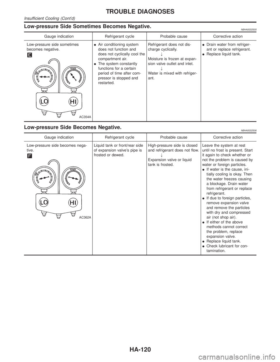
Low-pressure Side Sometimes Becomes Negative.NBHA0032S05
Gauge indication Refrigerant cycle Probable cause Corrective action
Low-pressure side sometimes
becomes negative.
AC354A
IAir conditioning system
does not function and
does not cyclically cool the
compartment air.
IThe system constantly
functions for a certain
period of time after com-
pressor is stopped and
restarted.Refrigerant does not dis-
charge cyclically.
"
Moisture is frozen at expan-
sion valve outlet and inlet.
"
Water is mixed with refriger-
ant.IDrain water from refriger-
ant or replace refrigerant.
IReplace liquid tank.
Low-pressure Side Becomes Negative.NBHA0032S06
Gauge indication Refrigerant cycle Probable cause Corrective action
Low-pressure side becomes nega-
tive.
AC362A
Liquid tank or front/rear side
of expansion valve's pipe is
frosted or dewed.High-pressure side is closed
and refrigerant does not flow.
"
Expansion valve or liquid
tank is frosted.Leave the system at rest
until no frost is present. Start
it again to check whether or
not the problem is caused by
water or foreign particles.
IIf water is the cause, ini-
tially cooling is okay. Then
the water freezes causing
a blockage. Drain water
from refrigerant or replace
refrigerant.
IIf due to foreign particles,
remove expansion valve
and remove the particles
with dry and compressed
air (not shop air).
IIf either of the above
methods cannot correct
the problem, replace
expansion valve.
IReplace liquid tank.
ICheck lubricant for con-
tamination.
TROUBLE DIAGNOSES
Insufficient Cooling (Cont'd)
HA-120
Page 1945 of 2395
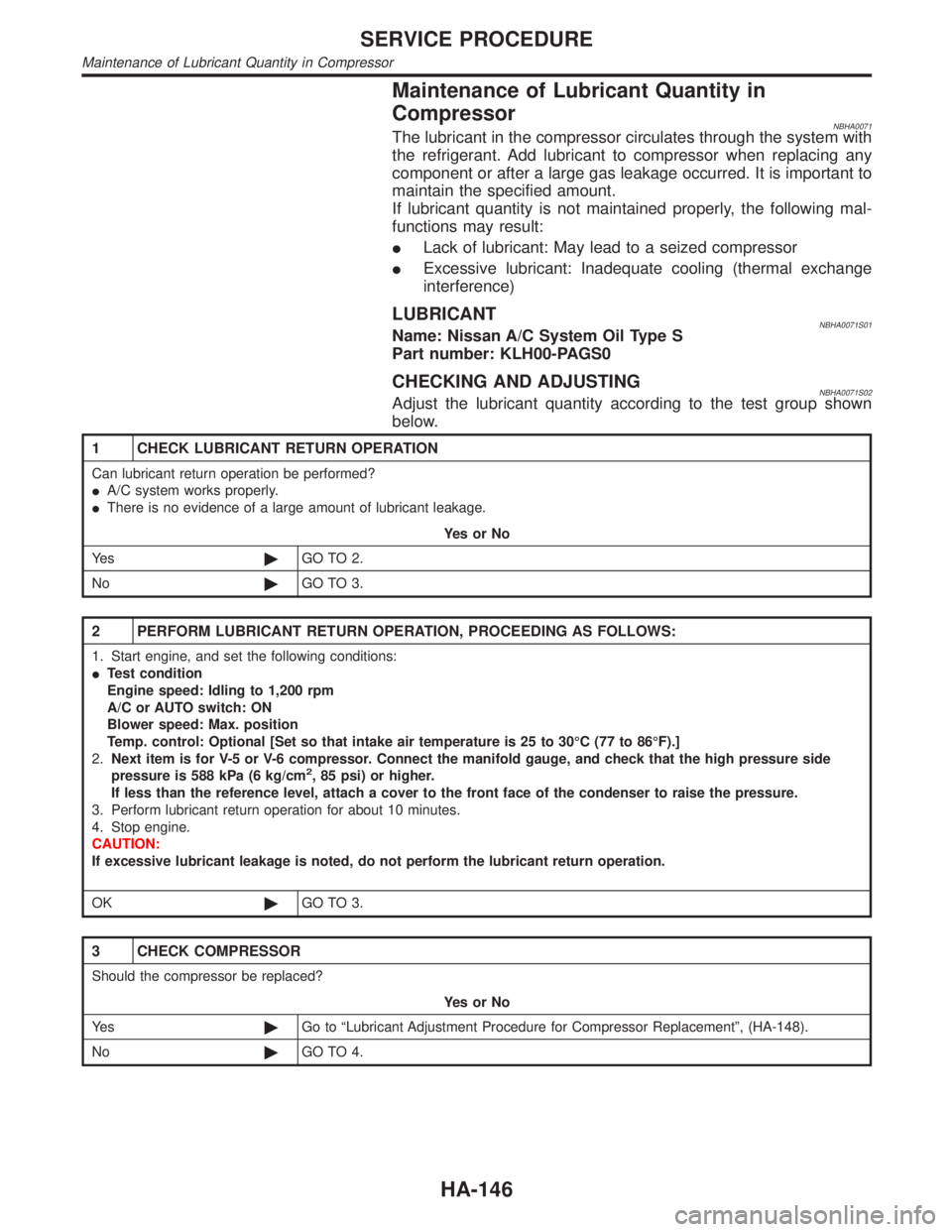
Maintenance of Lubricant Quantity in
Compressor
NBHA0071The lubricant in the compressor circulates through the system with
the refrigerant. Add lubricant to compressor when replacing any
component or after a large gas leakage occurred. It is important to
maintain the specified amount.
If lubricant quantity is not maintained properly, the following mal-
functions may result:
ILack of lubricant: May lead to a seized compressor
IExcessive lubricant: Inadequate cooling (thermal exchange
interference)
LUBRICANTNBHA0071S01Name: Nissan A/C System Oil Type S
Part number: KLH00-PAGS0
CHECKING AND ADJUSTINGNBHA0071S02Adjust the lubricant quantity according to the test group shown
below.
1 CHECK LUBRICANT RETURN OPERATION
Can lubricant return operation be performed?
IA/C system works properly.
IThere is no evidence of a large amount of lubricant leakage.
YesorNo
Ye s©GO TO 2.
No©GO TO 3.
2 PERFORM LUBRICANT RETURN OPERATION, PROCEEDING AS FOLLOWS:
1. Start engine, and set the following conditions:
ITest condition
Engine speed: Idling to 1,200 rpm
A/C or AUTO switch: ON
Blower speed: Max. position
Temp. control: Optional [Set so that intake air temperature is 25 to 30ÉC (77 to 86ÉF).]
2.Next item is for V-5 or V-6 compressor. Connect the manifold gauge, and check that the high pressure side
pressure is 588 kPa (6 kg/cm
2, 85 psi) or higher.
If less than the reference level, attach a cover to the front face of the condenser to raise the pressure.
3. Perform lubricant return operation for about 10 minutes.
4. Stop engine.
CAUTION:
If excessive lubricant leakage is noted, do not perform the lubricant return operation.
OK©GO TO 3.
3 CHECK COMPRESSOR
Should the compressor be replaced?
YesorNo
Ye s©Go to ªLubricant Adjustment Procedure for Compressor Replacementº, (HA-148).
No©GO TO 4.
SERVICE PROCEDURE
Maintenance of Lubricant Quantity in Compressor
HA-146
Page 1955 of 2395
5. When the A/C operating (compressor running), inject one
bottle (1/4 ounce /7.4 cc) of fluorescent dye through the low-
pressure service valve using dye injector tool J-41459 (refer to
the manufacture's operating instructions).
6. With the engine still running, disconnect the injector tool from
the service fitting.
CAUTION:
Be careful not to allow dye to spray or drip when disconnect-
ing the injector from the system.
NOTE:
If repairing the A/C system or replacing a component, pour the
dye directly into the open system connection and proceed
with the service procedures.
7. Operate the A/C system for a minimum of 20 minutes to mix
the dye with the system oil. Depending on the leak size, oper-
ating conditions and location of the leak, it may take from min-
utes to days for the dye to penetrate a leak and become visible.
SHA196FA
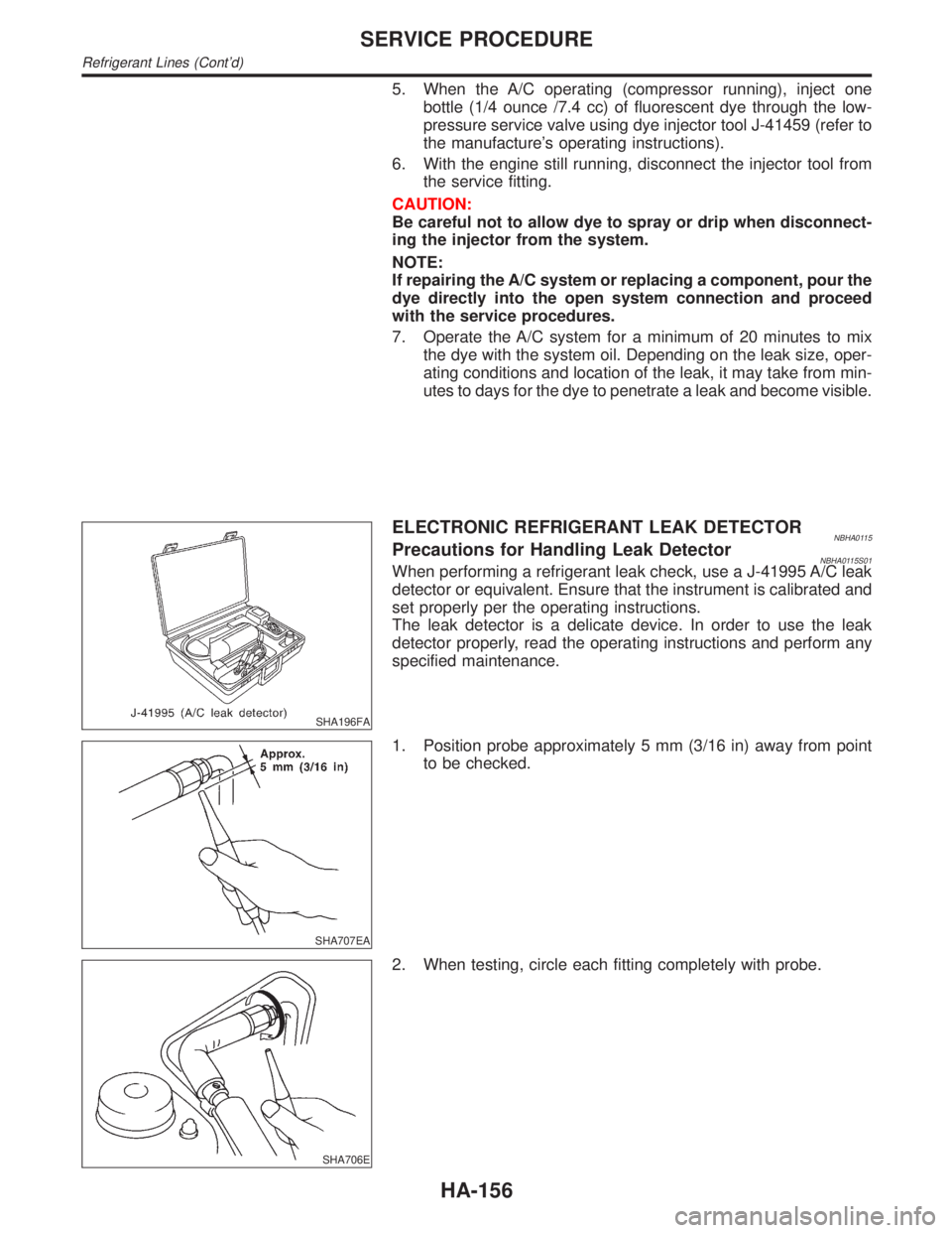
ELECTRONIC REFRIGERANT LEAK DETECTORNBHA0115Precautions for Handling Leak DetectorNBHA0115S01When performing a refrigerant leak check, use a J-41995 A/C leak
detector or equivalent. Ensure that the instrument is calibrated and
set properly per the operating instructions.
The leak detector is a delicate device. In order to use the leak
detector properly, read the operating instructions and perform any
specified maintenance.
SHA707EA
1. Position probe approximately 5 mm (3/16 in) away from point
to be checked.
SHA706E
2. When testing, circle each fitting completely with probe.
SERVICE PROCEDURE
Refrigerant Lines (Cont'd)
HA-156