2001 INFINITI QX4 ECO mode
[x] Cancel search: ECO modePage 1285 of 2395
Meter/Gauge Operation and Odo/Trip Meter
Segment Check in Diagnosis Mode
NBEL0200DIAGNOSIS FUNCTIONNBEL0200S01IOdo/trip meter segment can be checked in diagnosis mode.
IMeters/gauges can be checked in diagnosis mode.
HOW TO ALTERNATE DIAGNOSIS MODENBEL0200S021. Turn ignition switch to ON and change odo/trip meter to ªTRIP
Aº or ªTRIP Bº.
2. Turn ignition switch to OFF.
3. Turn ignition switch to ON when pushing odo/trip meter switch.
4. Push odo/trip meter switch 1 second.
5. Release odo/trip meter switch.
6. Push odo/trip meter switch more than three times within 7
seconds.
SEL176W
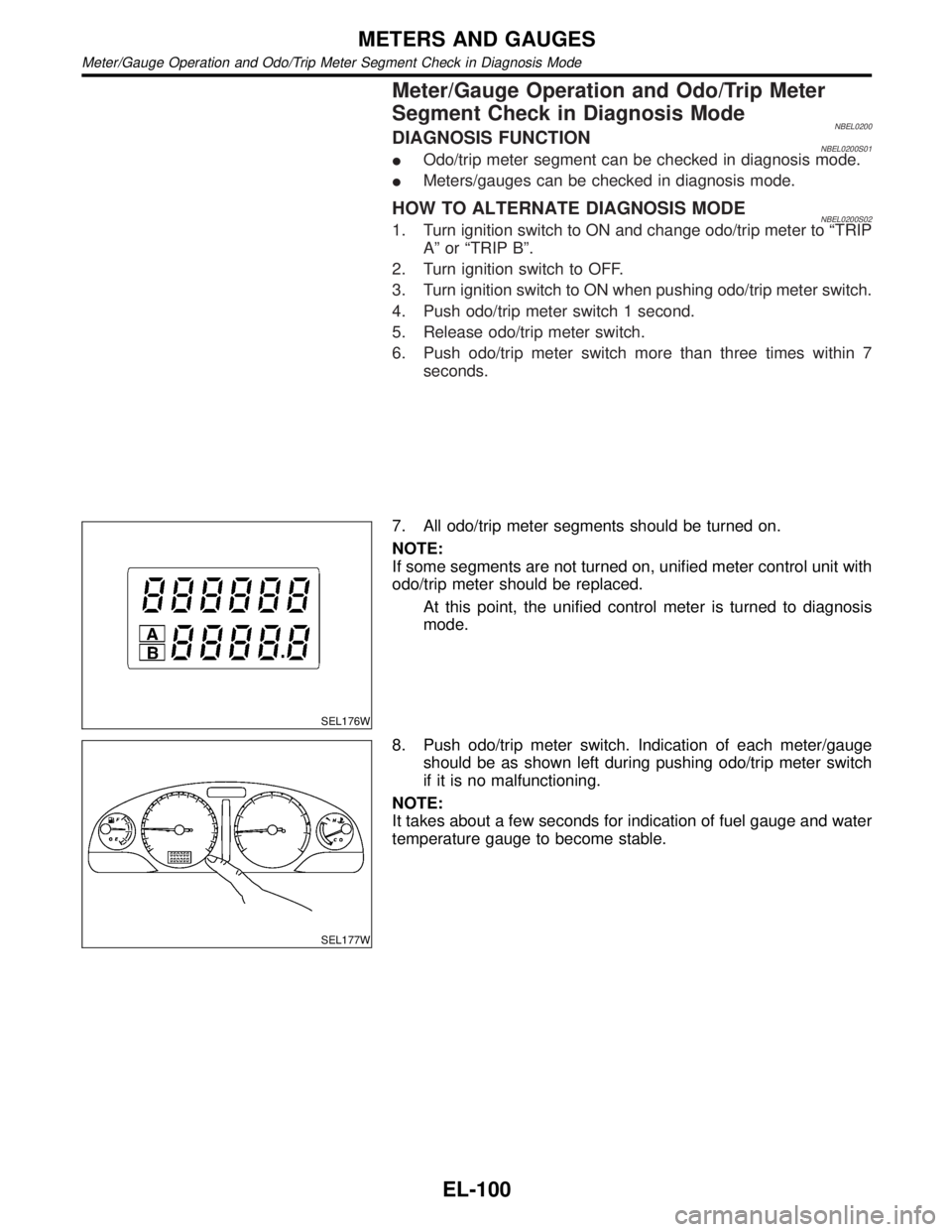
7. All odo/trip meter segments should be turned on.
NOTE:
If some segments are not turned on, unified meter control unit with
odo/trip meter should be replaced.
At this point, the unified control meter is turned to diagnosis
mode.
SEL177W
8. Push odo/trip meter switch. Indication of each meter/gauge
should be as shown left during pushing odo/trip meter switch
if it is no malfunctioning.
NOTE:
It takes about a few seconds for indication of fuel gauge and water
temperature gauge to become stable.
METERS AND GAUGES
Meter/Gauge Operation and Odo/Trip Meter Segment Check in Diagnosis Mode
EL-100
Page 1297 of 2395
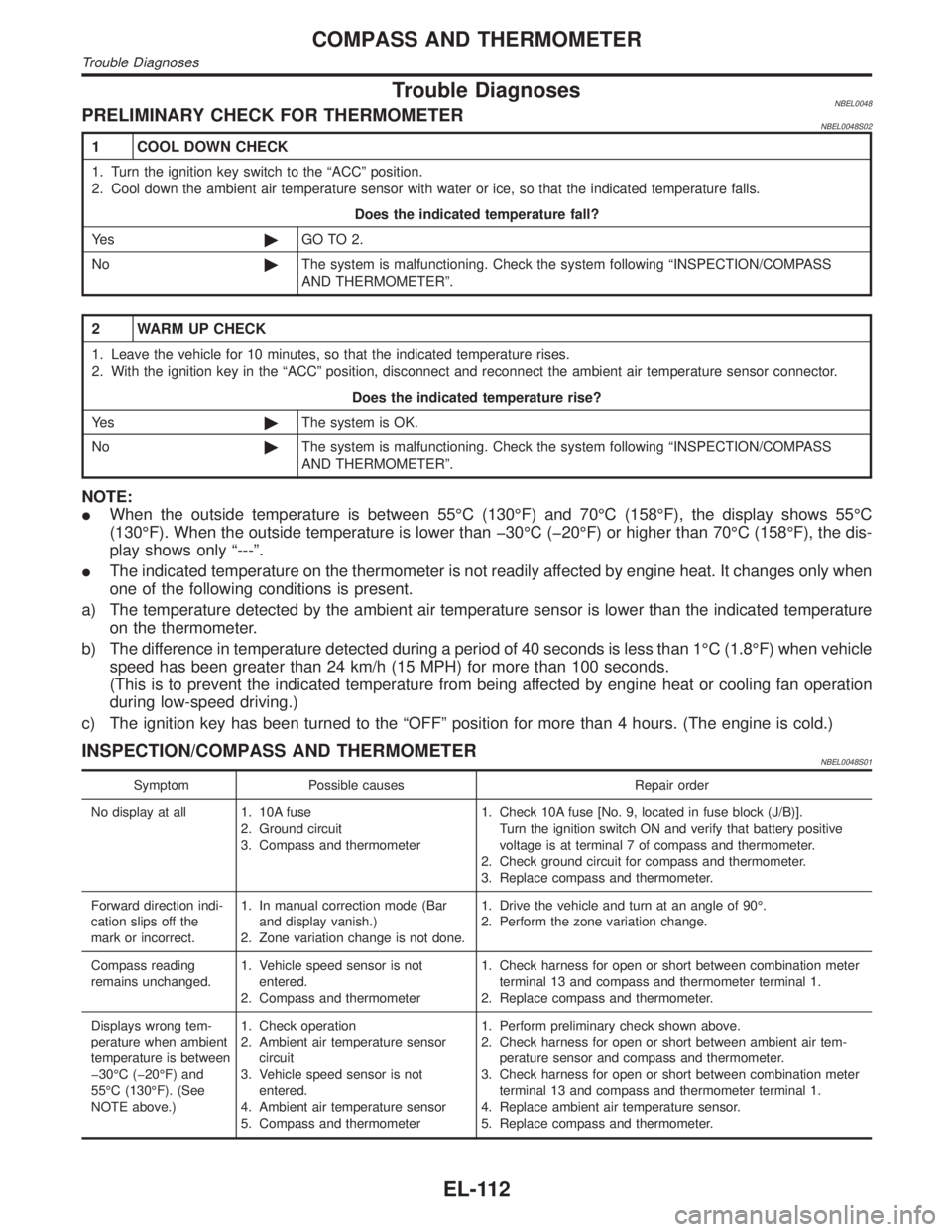
Trouble DiagnosesNBEL0048PRELIMINARY CHECK FOR THERMOMETERNBEL0048S02
1 COOL DOWN CHECK
1. Turn the ignition key switch to the ªACCº position.
2. Cool down the ambient air temperature sensor with water or ice, so that the indicated temperature falls.
Does the indicated temperature fall?
Ye s©GO TO 2.
No©The system is malfunctioning. Check the system following ªINSPECTION/COMPASS
AND THERMOMETERº.
2 WARM UP CHECK
1. Leave the vehicle for 10 minutes, so that the indicated temperature rises.
2. With the ignition key in the ªACCº position, disconnect and reconnect the ambient air temperature sensor connector.
Does the indicated temperature rise?
Ye s©The system is OK.
No©The system is malfunctioning. Check the system following ªINSPECTION/COMPASS
AND THERMOMETERº.
NOTE:
IWhen the outside temperature is between 55ÉC (130ÉF) and 70ÉC (158ÉF), the display shows 55ÉC
(130ÉF). When the outside temperature is lower than þ30ÉC (þ20ÉF) or higher than 70ÉC (158ÉF), the dis-
play shows only ª---º.
IThe indicated temperature on the thermometer is not readily affected by engine heat. It changes only when
one of the following conditions is present.
a) The temperature detected by the ambient air temperature sensor is lower than the indicated temperature
on the thermometer.
b) The difference in temperature detected during a period of 40 seconds is less than 1ÉC (1.8ÉF) when vehicle
speed has been greater than 24 km/h (15 MPH) for more than 100 seconds.
(This is to prevent the indicated temperature from being affected by engine heat or cooling fan operation
during low-speed driving.)
c) The ignition key has been turned to the ªOFFº position for more than 4 hours. (The engine is cold.)
INSPECTION/COMPASS AND THERMOMETERNBEL0048S01
Symptom Possible causes Repair order
No display at all 1. 10A fuse
2. Ground circuit
3. Compass and thermometer1. Check 10A fuse [No. 9, located in fuse block (J/B)].
Turn the ignition switch ON and verify that battery positive
voltage is at terminal 7 of compass and thermometer.
2. Check ground circuit for compass and thermometer.
3. Replace compass and thermometer.
Forward direction indi-
cation slips off the
mark or incorrect.1. In manual correction mode (Bar
and display vanish.)
2. Zone variation change is not done.1. Drive the vehicle and turn at an angle of 90É.
2. Perform the zone variation change.
Compass reading
remains unchanged.1. Vehicle speed sensor is not
entered.
2. Compass and thermometer1. Check harness for open or short between combination meter
terminal 13 and compass and thermometer terminal 1.
2. Replace compass and thermometer.
Displays wrong tem-
perature when ambient
temperature is between
þ30ÉC (þ20ÉF) and
55ÉC (130ÉF). (See
NOTE above.)1. Check operation
2. Ambient air temperature sensor
circuit
3. Vehicle speed sensor is not
entered.
4. Ambient air temperature sensor
5. Compass and thermometer1. Perform preliminary check shown above.
2. Check harness for open or short between ambient air tem-
perature sensor and compass and thermometer.
3. Check harness for open or short between combination meter
terminal 13 and compass and thermometer terminal 1.
4. Replace ambient air temperature sensor.
5. Replace compass and thermometer.
COMPASS AND THERMOMETER
Trouble Diagnoses
EL-112
Page 1298 of 2395
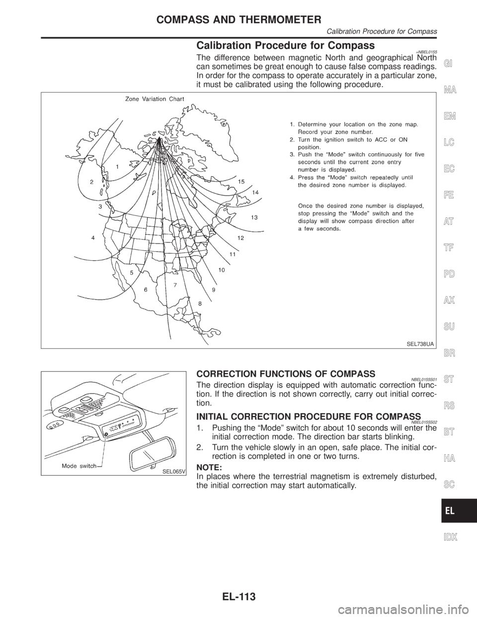
Calibration Procedure for Compass=NBEL0155The difference between magnetic North and geographical North
can sometimes be great enough to cause false compass readings.
In order for the compass to operate accurately in a particular zone,
it must be calibrated using the following procedure.
SEL738UA
SEL065V
CORRECTION FUNCTIONS OF COMPASSNBEL0155S01The direction display is equipped with automatic correction func-
tion. If the direction is not shown correctly, carry out initial correc-
tion.
INITIAL CORRECTION PROCEDURE FOR COMPASSNBEL0155S021. Pushing the ªModeº switch for about 10 seconds will enter the
initial correction mode. The direction bar starts blinking.
2. Turn the vehicle slowly in an open, safe place. The initial cor-
rection is completed in one or two turns.
NOTE:
In places where the terrestrial magnetism is extremely disturbed,
the initial correction may start automatically.
GI
MA
EM
LC
EC
FE
AT
TF
PD
AX
SU
BR
ST
RS
BT
HA
SC
IDX
COMPASS AND THERMOMETER
Calibration Procedure for Compass
EL-113
Page 1351 of 2395
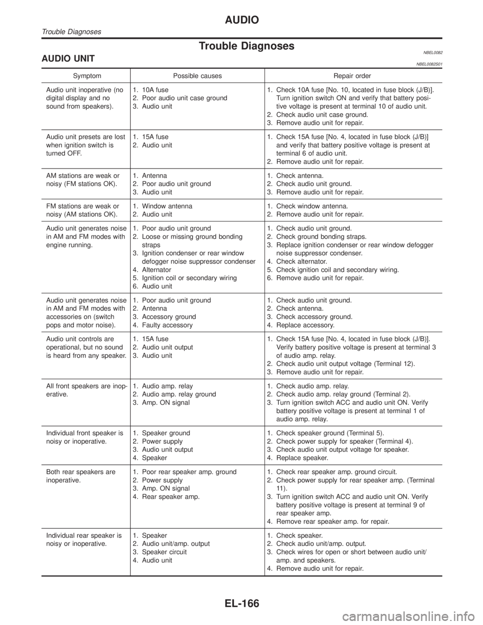
Trouble DiagnosesNBEL0082AUDIO UNITNBEL0082S01
Symptom Possible causes Repair order
Audio unit inoperative (no
digital display and no
sound from speakers).1. 10A fuse
2. Poor audio unit case ground
3. Audio unit1. Check 10A fuse [No. 10, located in fuse block (J/B)].
Turn ignition switch ON and verify that battery posi-
tive voltage is present at terminal 10 of audio unit.
2. Check audio unit case ground.
3. Remove audio unit for repair.
Audio unit presets are lost
when ignition switch is
turned OFF.1. 15A fuse
2. Audio unit1. Check 15A fuse [No. 4, located in fuse block (J/B)]
and verify that battery positive voltage is present at
terminal 6 of audio unit.
2. Remove audio unit for repair.
AM stations are weak or
noisy (FM stations OK).1. Antenna
2. Poor audio unit ground
3. Audio unit1. Check antenna.
2. Check audio unit ground.
3. Remove audio unit for repair.
FM stations are weak or
noisy (AM stations OK).1. Window antenna
2. Audio unit1. Check window antenna.
2. Remove audio unit for repair.
Audio unit generates noise
in AM and FM modes with
engine running.1. Poor audio unit ground
2. Loose or missing ground bonding
straps
3. Ignition condenser or rear window
defogger noise suppressor condenser
4. Alternator
5. Ignition coil or secondary wiring
6. Audio unit1. Check audio unit ground.
2. Check ground bonding straps.
3. Replace ignition condenser or rear window defogger
noise suppressor condenser.
4. Check alternator.
5. Check ignition coil and secondary wiring.
6. Remove audio unit for repair.
Audio unit generates noise
in AM and FM modes with
accessories on (switch
pops and motor noise).1. Poor audio unit ground
2. Antenna
3. Accessory ground
4. Faulty accessory1. Check audio unit ground.
2. Check antenna.
3. Check accessory ground.
4. Replace accessory.
Audio unit controls are
operational, but no sound
is heard from any speaker.1. 15A fuse
2. Audio unit output
3. Audio unit1. Check 15A fuse [No. 4, located in fuse block (J/B)].
Verify battery positive voltage is present at terminal 3
of audio amp. relay.
2. Check audio unit output voltage (Terminal 12).
3. Remove audio unit for repair.
All front speakers are inop-
erative.1. Audio amp. relay
2. Audio amp. relay ground
3. Amp. ON signal1. Check audio amp. relay.
2. Check audio amp. relay ground (Terminal 2).
3. Turn ignition switch ACC and audio unit ON. Verify
battery positive voltage is present at terminal 1 of
audio amp. relay.
Individual front speaker is
noisy or inoperative.1. Speaker ground
2. Power supply
3. Audio unit output
4. Speaker1. Check speaker ground (Terminal 5).
2. Check power supply for speaker (Terminal 4).
3. Check audio unit output voltage for speaker.
4. Replace speaker.
Both rear speakers are
inoperative.1. Poor rear speaker amp. ground
2. Power supply
3. Amp. ON signal
4. Rear speaker amp.1. Check rear speaker amp. ground circuit.
2. Check power supply for rear speaker amp. (Terminal
11).
3. Turn ignition switch ACC and audio unit ON. Verify
battery positive voltage is present at terminal 9 of
rear speaker amp.
4. Remove rear speaker amp. for repair.
Individual rear speaker is
noisy or inoperative.1. Speaker
2. Audio unit/amp. output
3. Speaker circuit
4. Audio unit1. Check speaker.
2. Check audio unit/amp. output.
3. Check wires for open or short between audio unit/
amp. and speakers.
4. Remove audio unit for repair.
AUDIO
Trouble Diagnoses
EL-166
Page 1382 of 2395

MALFUNCTION CODE TABLE=NBEL0213S02In this mode, a malfunction code is indicated by the number of flashes from the automatic drive positioner
indicator lamps (indicator lamp 1, indicator lamp 2) as shown below.
SEL597W
Code
No.Detected
itemsDiagnostic procedureRefer-
ence
pageCode
No.Detected
itemsDiagnostic procedureRefer-
ence
page
1Seat
slidingPROCEDURE 2
(Sliding encoder check)
PROCEDURE 6
(Sliding motor check)EL-203
EL-2114Seat
lifting
rearPROCEDURE 5
[Lifting encoder (rear) check]
PROCEDURE 9
[Lifting motor (rear) check]EL-209
EL-214
2Seat
recliningPROCEDURE 3
(Reclining encoder check)
PROCEDURE 7
(Reclining motor check)EL-205
EL-2129Vehicle
speed
sensorPROCEDURE 12
(Vehicle speed sensor check)EL-217
3Seat
lifting
frontPROCEDURE 4
[Lifting encoder (front) check]
PROCEDURE 8
[Lifting motor (front) check]EL-207
EL-213
GI
MA
EM
LC
EC
FE
AT
TF
PD
AX
SU
BR
ST
RS
BT
HA
SC
IDX
AUTOMATIC DRIVE POSITIONER
On Board Diagnosis (Cont'd)
EL-197
Page 1456 of 2395
When the front door switch LH is OPEN, ground is supplied
Ito smart entrance control unit terminal 29
Ithrough front door switch LH terminal 1
Ito front door switch LH terminal 2
Ithrough body grounds B11, B22 and D210.
When the front door switch RH is OPEN, ground is supplied
Ito smart entrance control unit terminal 40
Ithrough front door switch RH body ground.
When the other door switches are OPEN, ground is supplied
Ito smart entrance control unit terminal 28
Ithrough other door switches body grounds.
Remote controller signal is inputted to smart entrance control unit (The antenna of the system is combined
with smart entrance control unit).
OPERATIONNBEL0112S03The multi-remote control system controls operation of the
Ipower door lock
Iinterior lamp
Ipanic alarm
Ihazard and horn reminder
OPERATED PROCEDURENBEL0112S02Power Door Lock OperationNBEL0112S0201Smart entrance control unit receives a LOCK signal from remote controller. Smart entrance control unit locks
all doors with input of LOCK signal from remote controller.
When an UNLOCK signal is sent from remote controller once, driver's door will be unlocked.
Then, if an UNLOCK signal is sent from remote controller again within 5 seconds, all other door will be
unlocked.
Hazard and Horn ReminderNBEL0112S0204When smart entrance control unit receives LOCK or UNLOCK signal from remote controller with all doors
closed, ground is supplied
Ito multi-remote control relay terminal 2
Ithrough smart entrance control unit terminal 7, and
Ito horn relay terminal 2
Ithrough smart entrance control unit terminal 19
Multi-remote control relay and horn relay are now energized, and hazard warning lamp flashes and horn
sounds as a reminder.
The hazard and horn reminder has a horn chirp mode (C mode) and a non-horn chirp mode (S mode).
Operating function of hazard and horn reminder
Horn chirp mode (C mode) Non-horn chirp mode (S mode)
Hazard warning lamp
flashHorn soundHazard warning lamp
flashHorn sound
Lock Twice Once Twice Ð
Unlock Once Ð Ð Ð
How to change hazard and horn reminder mode
When LOCK and UNLOCK signals are sent from the remote controller for more than 2 seconds at the same
time, the hazard and horn reminder mode is changed and hazard warning lamp flashes and horn sounds as
follows:
GI
MA
EM
LC
EC
FE
AT
TF
PD
AX
SU
BR
ST
RS
BT
HA
SC
IDX
MULTI-REMOTE CONTROL SYSTEM
System Description (Cont'd)
EL-271
Page 1481 of 2395
![INFINITI QX4 2001 Factory Service Manual Ito smart entrance control unit terminal 33.
With the ignition switch in the ACC or ON position, power is supplied
Ithrough 10A fuse [No. 10, located in the fuse block (J/B)]
Ito smart entrance contro INFINITI QX4 2001 Factory Service Manual Ito smart entrance control unit terminal 33.
With the ignition switch in the ACC or ON position, power is supplied
Ithrough 10A fuse [No. 10, located in the fuse block (J/B)]
Ito smart entrance contro](/manual-img/42/57027/w960_57027-1480.png)
Ito smart entrance control unit terminal 33.
With the ignition switch in the ACC or ON position, power is supplied
Ithrough 10A fuse [No. 10, located in the fuse block (J/B)]
Ito smart entrance control unit terminal 21.
Ground is supplied
Ito smart entrance control unit terminal 16
Ithrough body grounds M77 and M111.
INITIAL CONDITION TO ACTIVATE THE SYSTEMNBEL0120S02The operation of the theft warning system is controlled by the doors, hood and glass hatch.
To activate the theft warning system, the smart entrance control unit must receive signals indicating the doors,
hood and glass hatch are closed and the doors are locked.
When a door is open, smart entrance control unit terminal 28, 29 or 40 receives a ground signal from each
door switch.
When a door is unlocked, smart entrance control unit terminal 26, 36 or 37 receives a ground signal from ter-
minal 4 of each door unlock sensor or terminal 1 of back door unlock sensor.
When the hood is open, smart entrance control unit terminal 27 receives a ground signal
Ifrom terminal 1 of the hood switch
Ithrough body grounds E13 and E41.
When the glass hatch is open, smart entrance control unit terminal 38 receives a ground signal
Ifrom terminal 1 of the glass hatch switch
Ithrough body grounds D210, B11 and B22.
When the doors are locked with key or multi-remote controller and none of the described conditions exist, the
theft warning system will automatically shift to armed mode.
THEFT WARNING SYSTEM ACTIVATION (WITH KEY OR REMOTE CONTROLLER USED TO
LOCK DOORS)
NBEL0120S03If the key is used to lock doors, terminal 41 receives a ground signal
Ifrom terminal 3 of the key cylinder switch LH
Ithrough back grounds M77 and M111
Ifrom terminal 1 of the back door key cylinder switch
Ithrough body grounds B11, B22 and D210.
If this signal or lock signal from remote controller is received by the smart entrance control unit, the theft
warning system will activate automatically.
Once the theft warning system has been activated, smart entrance control unit terminal 31 supplies ground to
terminal 2 of the security indicator lamp.
The security lamp will illuminate for approximately 30 seconds and then blink.
Now the theft warning system is in armed phase.
THEFT WARNING SYSTEM ALARM OPERATIONNBEL0120S04The theft warning system is triggered by
Iopening a door
Iopening the hood or the glass hatch
Iunlocking door without using the key or multi-remote controller.
Once the theft warning system is in armed phase, if the smart entrance control unit receives a ground signal
at terminal 26, 36, 37 (door unlock sensor), 28, 29, 40 (door switch), 38 (glass hatch switch) or 27 (hood
switch), the theft warning system will be triggered. The headlamps flash and the horn sounds intermittently.
Power is supplied at all times
Ithrough 7.5A fuse (No. 52, located in fuse and fusible link box)
Ito horn relay terminals 1 and 3.
Ithrough 10A fuse (No. 54, located in fuse and fusible link box)
Ito horn relay terminal 6.
When the theft warning system is triggered, ground is supplied intermittently
Ifrom terminal 4 of the smart entrance control unit
Ito headlamp relay LH and RH terminal 2 and
Ifrom terminal 19 of the smart entrance control unit
THEFT WARNING SYSTEM
System Description (Cont'd)
EL-296
Page 1531 of 2395

DIAGNOSTIC PROCEDURE 7=NBEL0224S11Self-diagnostic results:
ªLOCK MODEº displayed on CONSULT-II screen
1 CONFIRM SELF-DIAGNOSTIC RESULTS
Confirm SELF-DIAGNOSTIC RESULTS ªLOCK MODEº is displayed on CONSULT-II screen.
SEL371X
Is CONSULT-II screen displayed as above?
Ye s©GO TO 2.
No©GO TO SYMPTOM MATRIX CHART 1.
2 ESCAPE FROM LOCK MODE
1. Turn ignition switch OFF.
2. Turn ignition switch ON with registered key. (Do not start engine.) Wait 5 seconds.
3. Return the key to OFF position.
4. Repeat steps 2 and 3 twice (total of three cycles).
5. Start the engine.
Does engine start?
Ye s©System is OK.
(Now system is escaped from ªLOCK MODEº.)
No©GO TO 3.
3 CHECK IMMU ILLUSTRATION
Check IMMU installation. Refer to ªHow to Replace IMMUº in EL-347.
OK or NG
OK©GO TO 4.
NG©Reinstall IMMU correctly.
IVIS (INFINITI VEHICLE IMMOBILIZER SYSTEM Ð NATS)
Trouble Diagnoses (Cont'd)
EL-346