2001 INFINITI QX4 hood open
[x] Cancel search: hood openPage 889 of 2395

SEF565X
DTC Confirmation ProcedureNBEC0219
SEF566X
SEF874X
SEF567X
NOTE:
IIf DTC P0440 or P1440 is displayed with P1448, perform
trouble diagnosis for DTC P1448 first. (See EC-573.)
IIf ªDTC Confirmation Procedureº has been previously
conducted, always turn ignition switch ªOFFº and wait at least
10 seconds before conducting the next test.
TESTING CONDITION:
IPerform ªDTC WORK SUPPORTº when the fuel level is
between 1/4 to 3/4 full and vehicle is placed on flat level
surface.
IOpen engine hood before conducting the following proce-
dure.
WITH CONSULT-IINBEC0219S011) Turn ignition switch ªONº.
2) Turn ignition switch ªOFFº and wait at least 10 seconds.
3) Turn ignition switch ªONº and select ªDATA MONITORº mode
with CONSULT-II.
4) Make sure that the following conditions are met.
COOLAN TEMP/S: 0 - 70ÉC (32 - 158ÉF)
INT/A TEMP SE: 0 - 30ÉC (32 - 86ÉF)
5) Select ªEVAP SML LEAK P0440/P1440º of ªEVAPORATIVE
SYSTEMº in ªDTC WORK SUPPORTº mode with CONSULT-
II.
Follow the instruction displayed.
NOTE:
If the engine speed cannot be maintained within the range dis-
played on the CONSULT-II screen, go to ªBasic Inspectionº,
EC-101.
6) Make sure that ªOKº is displayed.
If ªNGº is displayed, refer to ªDiagnostic Procedureº, EC-355.
NOTE:
Make sure that EVAP hoses are connected to EVAP canister
purge volume control solenoid valve properly.
WITH GSTNBEC0219S02NOTE:
Be sure to read the explanation of ªDriving Patternº on EC-66
before driving vehicle.
1) Start engine.
2) Drive vehicle according to ªDriving Patternº, EC-66.
3) Stop vehicle.
4) Select ªMODE 1º with GST.
IIf SRT of EVAP system is not set yet, go to the following step.
IIf SRT of EVAP system is set, the result will be OK.
5) Turn ignition switch ªOFFº and wait at least 10 seconds.
6) Start engine.
It is not necessary to cool engine down before driving.
7) Drive vehicle again according to the ªDriving Patternº, EC-66.
8) Stop vehicle.
9) Select ªMODE 3º with GST.
IIf P0440 or P1440 is displayed on the screen, go to ªDiagnos-
tic Procedureº, EC-355.
IIf P1447 is displayed on the screen, go to ªDiagnostic Proce-
dureº for DTC P1447, EC-564.
DTC P0440 EVAP CONTROL SYSTEM (SMALL LEAK) (NEGATIVE PRESSURE)
DTC Confirmation Procedure
EC-354
Page 931 of 2395

SEF565X
DTC Confirmation ProcedureNBEC0646
SEF566X
SEF874X
SEF567X
CAUTION:
Never remove fuel filler cap during the DTC Confirmation Pro-
cedure.
NOTE:
IIf DTC P0455 is displayed with P1448, perform trouble
diagnosis for DTC P1448 first. (See EC-573.)
IMake sure that EVAP hoses are connected to EVAP canis-
ter purge volume control solenoid valve properly.
IIf ªDTC Confirmation Procedureº has been previously
conducted, always turn ignition switch ªOFFº and wait at least
10 seconds before conducting the next test.
TESTING CONDITION:
IPerform ªDTC WORK SUPPORTº when the fuel level is
between 1/4 to 3/4 full and vehicle is placed on flat level
surface.
IOpen engine hood before conducting the following proce-
dures.
WITH CONSULT-IINBEC0646S011) Tighten fuel filler cap securely until ratcheting sound is heard.
2) Turn ignition switch ªONº.
3) Turn ignition switch ªOFFº and wait at least 10 seconds.
4) Turn ignition switch ªONº and select ªDATA MONITORº mode
with CONSULT-II.
5) Make sure that the following conditions are met.
COOLAN TEMP/S: 0 - 70ÉC (32 - 158ÉF)
INT/A TEMP SE: 0 - 60ÉC (32 - 140ÉF)
6) Select ªEVAP SML LEAK P0440/P1440º of ªEVAPORATIVE
SYSTEMº in ªDTC WORK SUPPORTº mode with CONSULT-
II.
Follow the instruction displayed.
NOTE:
If the engine speed cannot be maintained within the range dis-
played on the CONSULT-II screen, go to ªBasic Inspectionº,
EC-101.
7) Make sure that ªOKº is displayed.
If ªNGº is displayed, select ªSELF-DIAG RESULTSº mode and
make sure that ªEVAP GROSS LEAK [P0455]º is displayed. If
it is displayed, refer to ªDiagnostic Procedureº, EC-397.
If P0440 is displayed, perform ªDiagnostic Procedureº for DTC
P0440.
WITH GSTNBEC0646S02NOTE:
Be sure to read the explanation of ªDriving Patternº on EC-66
before driving vehicle.
1) Start engine.
2) Drive vehicle according to ªDriving Patternº, EC-66.
3) Stop vehicle.
4) Select ªMODE 1º with GST.
IIf SRT of EVAP system is not set yet, go to the following step.
IIf SRT of EVAP system is set, the result will be OK.
5) Turn ignition switch ªOFFº and wait at least 10 seconds.
6) Start engine.
It is not necessary to cool engine down before driving.
7) Drive vehicle again according to the ªDriving Patternº, EC-66.
DTC P0455 EVAP CONTROL SYSTEM (GROSS LEAK)
DTC Confirmation Procedure
EC-396
Page 959 of 2395

SEF058Y
PROCEDURE FOR MALFUNCTION ANBEC0253S01TESTING CONDITION:
Before performing the following procedure, confirm that bat-
tery voltage is more than 10.5V with ignition switch ªONº.
With CONSULT-IINBEC0253S01011) Start engine and warm it up to normal operating temperature.
2) Turn ignition switch ªOFFº and wait at least 10 seconds.
3) Perform ªIdle Air Volume Learningº (see EC-57).
4) Turn ignition switch ªOFFº and wait at least 10 seconds.
5) Turn ignition switch ªONº.
6) Select ªDATA MONITORº mode with CONSULT-II.
7) Start engine and let it idle.
8) Keep engine speed at 2,500 rpm for three seconds, then let it
idle for three seconds.
Do not rev engine to more than 3,000 rpm.
9) Perform step 4 once more.
10) If 1st trip DTC is detected, go to ªDiagnostic Procedureº,
EC-426.
With GSTNBEC0253S0102Follow the procedure ªWith CONSULT-IIº above.
SEF174Y
PROCEDURE FOR MALFUNCTION BNBEC0253S02TESTING CONDITION:
IBefore performing the following procedure, confirm that
battery voltage is more than 11V at idle.
IAlways perform the test at a temperature above þ10ÉC
(14ÉF).
With CONSULT-IINBEC0253S02011) Open engine hood.
2) Start engine and warm it up to normal operating temperature.
3) Turn ignition switch ªOFFº and wait at least 10 seconds.
4) Perform ªIdle Air Volume Learningº (see EC-57).
5) Turn ignition switch ªOFFº and wait at least 10 seconds.
6) Turn ignition switch ªONº again and select ªDATA MONITORº
mode with CONSULT-II
7) Start engine and run it for at least 1 minute at idle speed.
8) If 1st trip DTC is detected, go to ªDiagnostic Procedureº,
EC-426.
With GSTNBEC0253S0202Follow the procedure ªWith CONSULT-IIº above.
DTC P0505 IDLE AIR CONTROL VALVE (IACV) Ð AUXILIARY AIR CONTROL
(AAC) VALVE
DTC Confirmation Procedure (Cont'd)
EC-424
Page 1062 of 2395

IEVAP purge line rubber tube bent.
IBlocked or bent rubber tube to EVAP control system pressure
sensor
ILoose or disconnected rubber tube
IEVAP canister vent control valve and the circuit
IEVAP canister purge volume control solenoid valve
IAbsolute pressure sensor
IFuel tank temperature sensor
IO-ring of EVAP canister vent control valve is missing or dam-
aged.
IWater separator
IEVAP canister is saturated with water.
IFuel level sensor and the circuit
IEVAP control system pressure sensor
SEF881X
SEF882X
SEF883X
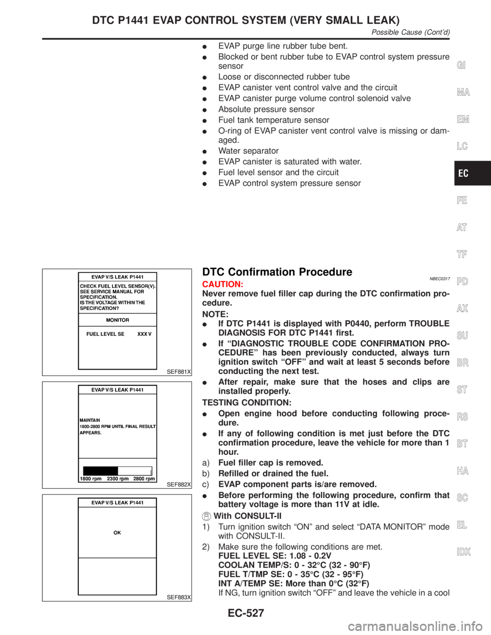
DTC Confirmation ProcedureNBEC0317CAUTION:
Never remove fuel filler cap during the DTC confirmation pro-
cedure.
NOTE:
IIf DTC P1441 is displayed with P0440, perform TROUBLE
DIAGNOSIS FOR DTC P1441 first.
IIf ªDIAGNOSTIC TROUBLE CODE CONFIRMATION PRO-
CEDUREº has been previously conducted, always turn
ignition switch ªOFFº and wait at least 5 seconds before
conducting the next test.
IAfter repair, make sure that the hoses and clips are
installed properly.
TESTING CONDITION:
IOpen engine hood before conducting following proce-
dure.
IIf any of following condition is met just before the DTC
confirmation procedure, leave the vehicle for more than 1
hour.
a)Fuel filler cap is removed.
b)Refilled or drained the fuel.
c)EVAP component parts is/are removed.
IBefore performing the following procedure, confirm that
battery voltage is more than 11V at idle.
With CONSULT-II
1) Turn ignition switch ªONº and select ªDATA MONITORº mode
with CONSULT-II.
2) Make sure the following conditions are met.
FUEL LEVEL SE: 1.08 - 0.2V
COOLAN TEMP/S: 0 - 32ÉC (32 - 90ÉF)
FUEL T/TMP SE: 0 - 35ÉC (32 - 95ÉF)
INT A/TEMP SE: More than 0ÉC (32ÉF)
If NG, turn ignition switch ªOFFº and leave the vehicle in a cool
GI
MA
EM
LC
FE
AT
TF
PD
AX
SU
BR
ST
RS
BT
HA
SC
EL
IDX
DTC P1441 EVAP CONTROL SYSTEM (VERY SMALL LEAK)
Possible Cause (Cont'd)
EC-527
Page 1109 of 2395

Possible CauseNBEC0591IEVAP canister vent control valve
IEVAP control system pressure sensor and circuit
IBlocked rubber tube to EVAP canister vent control valve
IWater separator
IEVAP canister is saturated with water.
IVacuum cut valve
DTC Confirmation ProcedureNBEC0342NOTE:
IIf DTC P1448 is displayed with P0440 or P1440, perform
trouble diagnosis for DTC P1448 first.
IIf ªDTC Confirmation Procedureº has been previously
conducted, always turn ignition switch ªOFFº and wait at least
10 seconds before conducting the next test.
SEF565X
SEF566X
SEF567X
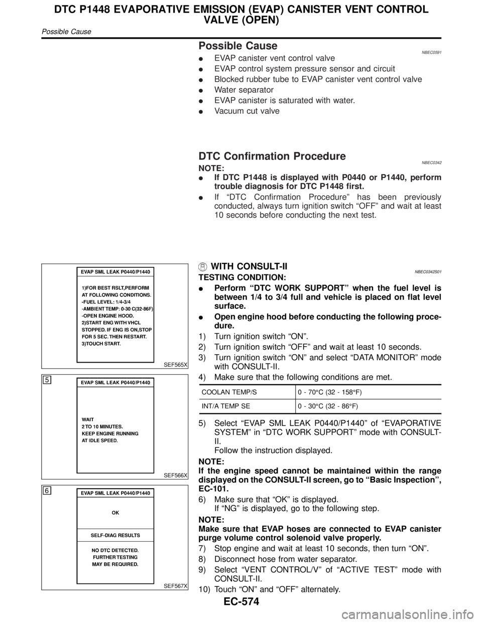
WITH CONSULT-IINBEC0342S01TESTING CONDITION:
IPerform ªDTC WORK SUPPORTº when the fuel level is
between 1/4 to 3/4 full and vehicle is placed on flat level
surface.
IOpen engine hood before conducting the following proce-
dure.
1) Turn ignition switch ªONº.
2) Turn ignition switch ªOFFº and wait at least 10 seconds.
3) Turn ignition switch ªONº and select ªDATA MONITORº mode
with CONSULT-II.
4) Make sure that the following conditions are met.
COOLAN TEMP/S 0 - 70ÉC (32 - 158ÉF)
INT/A TEMP SE 0 - 30ÉC (32 - 86ÉF)
5) Select ªEVAP SML LEAK P0440/P1440º of ªEVAPORATIVE
SYSTEMº in ªDTC WORK SUPPORTº mode with CONSULT-
II.
Follow the instruction displayed.
NOTE:
If the engine speed cannot be maintained within the range
displayed on the CONSULT-II screen, go to ªBasic Inspectionº,
EC-101.
6) Make sure that ªOKº is displayed.
If ªNGº is displayed, go to the following step.
NOTE:
Make sure that EVAP hoses are connected to EVAP canister
purge volume control solenoid valve properly.
7) Stop engine and wait at least 10 seconds, then turn ªONº.
8) Disconnect hose from water separator.
9) Select ªVENT CONTROL/Vº of ªACTIVE TESTº mode with
CONSULT-II.
10) Touch ªONº and ªOFFº alternately.
DTC P1448 EVAPORATIVE EMISSION (EVAP) CANISTER VENT CONTROL
VALVE (OPEN)
Possible Cause
EC-574
Page 1480 of 2395

System DescriptionNBEL0120DESCRIPTIONNBEL0120S011. Operation FlowNBEL0120S0101
SEL334W
2. Setting The Theft Warning SystemNBEL0120S0102Initial condition
1) Close all doors.
2) Close hood and glass hatch.
Disarmed phase
When the theft warning system is in the disarmed phase, the security indicator lamp blinks every 2.6 seconds.
Pre-armed phase and armed phase
The theft warning system turns into the ªpre-armedº phase when hood, glass hatch and all doors are closed
and the doors are locked by key or multi-remote controller. (The security indicator lamp illuminates.)
After about 30 seconds, the system automatically shifts into the ªarmedº phase (the system is set). (The
security indicator lamp blinks every 2.6 seconds.)
3. Canceling The Set Theft Warning SystemNBEL0120S0103When the following 1) or 2) operation is performed, the armed phase is canceled.
1) Unlock the doors with the key or multi-remote controller.
2) Open the glass hatch with the key.
4. Activating The Alarm Operation of The Theft Warning SystemNBEL0120S0104Make sure the system is in the armed phase. (The security indicator lamp blinks every 2.6 seconds.)
When any of the following operations is performed, the system sounds the horns and flashes the headlamps
for about 50 seconds.
1) Engine hood, glass hatch or any door is opened before unlocking door with key or multi-remote control-
ler.
2) Door is unlocked without using key or multi-remote controller.
3) Disconnecting and connecting the battery connector before canceling armed phase.
POWER SUPPLY AND GROUNDNBEL0120S07Power is supplied at all times
Ithrough 7.5A fuse [No. 24, located in the fuse block (J/B)]
Ito security indicator lamp terminal 1, and
Ito smart entrance control unit terminal 10.
With the ignition switch in the ON or START position, power is supplied
Ithrough 7.5A fuse [No. 11, located in the fuse block (J/B)]
GI
MA
EM
LC
EC
FE
AT
TF
PD
AX
SU
BR
ST
RS
BT
HA
SC
IDX
THEFT WARNING SYSTEM
System Description
EL-295
Page 1481 of 2395
![INFINITI QX4 2001 Factory Service Manual Ito smart entrance control unit terminal 33.
With the ignition switch in the ACC or ON position, power is supplied
Ithrough 10A fuse [No. 10, located in the fuse block (J/B)]
Ito smart entrance contro INFINITI QX4 2001 Factory Service Manual Ito smart entrance control unit terminal 33.
With the ignition switch in the ACC or ON position, power is supplied
Ithrough 10A fuse [No. 10, located in the fuse block (J/B)]
Ito smart entrance contro](/manual-img/42/57027/w960_57027-1480.png)
Ito smart entrance control unit terminal 33.
With the ignition switch in the ACC or ON position, power is supplied
Ithrough 10A fuse [No. 10, located in the fuse block (J/B)]
Ito smart entrance control unit terminal 21.
Ground is supplied
Ito smart entrance control unit terminal 16
Ithrough body grounds M77 and M111.
INITIAL CONDITION TO ACTIVATE THE SYSTEMNBEL0120S02The operation of the theft warning system is controlled by the doors, hood and glass hatch.
To activate the theft warning system, the smart entrance control unit must receive signals indicating the doors,
hood and glass hatch are closed and the doors are locked.
When a door is open, smart entrance control unit terminal 28, 29 or 40 receives a ground signal from each
door switch.
When a door is unlocked, smart entrance control unit terminal 26, 36 or 37 receives a ground signal from ter-
minal 4 of each door unlock sensor or terminal 1 of back door unlock sensor.
When the hood is open, smart entrance control unit terminal 27 receives a ground signal
Ifrom terminal 1 of the hood switch
Ithrough body grounds E13 and E41.
When the glass hatch is open, smart entrance control unit terminal 38 receives a ground signal
Ifrom terminal 1 of the glass hatch switch
Ithrough body grounds D210, B11 and B22.
When the doors are locked with key or multi-remote controller and none of the described conditions exist, the
theft warning system will automatically shift to armed mode.
THEFT WARNING SYSTEM ACTIVATION (WITH KEY OR REMOTE CONTROLLER USED TO
LOCK DOORS)
NBEL0120S03If the key is used to lock doors, terminal 41 receives a ground signal
Ifrom terminal 3 of the key cylinder switch LH
Ithrough back grounds M77 and M111
Ifrom terminal 1 of the back door key cylinder switch
Ithrough body grounds B11, B22 and D210.
If this signal or lock signal from remote controller is received by the smart entrance control unit, the theft
warning system will activate automatically.
Once the theft warning system has been activated, smart entrance control unit terminal 31 supplies ground to
terminal 2 of the security indicator lamp.
The security lamp will illuminate for approximately 30 seconds and then blink.
Now the theft warning system is in armed phase.
THEFT WARNING SYSTEM ALARM OPERATIONNBEL0120S04The theft warning system is triggered by
Iopening a door
Iopening the hood or the glass hatch
Iunlocking door without using the key or multi-remote controller.
Once the theft warning system is in armed phase, if the smart entrance control unit receives a ground signal
at terminal 26, 36, 37 (door unlock sensor), 28, 29, 40 (door switch), 38 (glass hatch switch) or 27 (hood
switch), the theft warning system will be triggered. The headlamps flash and the horn sounds intermittently.
Power is supplied at all times
Ithrough 7.5A fuse (No. 52, located in fuse and fusible link box)
Ito horn relay terminals 1 and 3.
Ithrough 10A fuse (No. 54, located in fuse and fusible link box)
Ito horn relay terminal 6.
When the theft warning system is triggered, ground is supplied intermittently
Ifrom terminal 4 of the smart entrance control unit
Ito headlamp relay LH and RH terminal 2 and
Ifrom terminal 19 of the smart entrance control unit
THEFT WARNING SYSTEM
System Description (Cont'd)
EL-296
Page 1492 of 2395

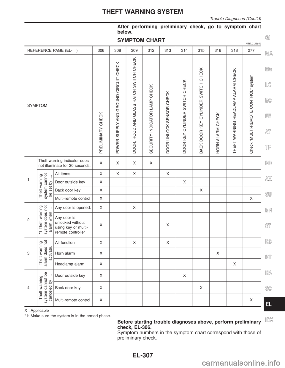
After performing preliminary check, go to symptom chart
below.
SYMPTOM CHARTNBEL0123S02
REFERENCE PAGE (EL- ) 306 308 309 312 313 314 315 316 318 277
SYMPTOM
PRELIMINARY CHECK
POWER SUPPLY AND GROUND CIRCUIT CHECK
DOOR, HOOD AND GLASS HATCH SWITCH CHECK
SECURITY INDICATOR LAMP CHECK
DOOR UNLOCK SENSOR CHECK
DOOR KEY CYLINDER SWITCH CHECK
BACK DOOR KEY CYLINDER SWITCH CHECK
HORN ALARM CHECK
THEFT WARNING HEADLAMP ALARM CHECK
Check ªMULTI-REMOTE CONTROLº system.
1Theft warning indicator does
not illuminate for 30 seconds.XXXX
Theft warning
system cannot
be set by ....
All items X X X X
Door outside key X X
Back door key X X
Multi-remote control XX
2
*1 Theft warning
system does not
alarm when ...
Any door is opened. X X
Any door is
unlocked without
using key or multi-
remote controllerXX
3
Theft warning
alarm does not
activate.
All function X X X
Horn alarm X X
Headlamp alarm XX
4
Theft warning
system cannot be
canceled by ....
Door outside key X X
Back door key X X
Multi-remote control XX
X : Applicable
*1: Make sure the system is in the armed phase.
Before starting trouble diagnoses above, perform preliminary
check, EL-306.
Symptom numbers in the symptom chart correspond with those of
preliminary check.
GI
MA
EM
LC
EC
FE
AT
TF
PD
AX
SU
BR
ST
RS
BT
HA
SC
IDX
THEFT WARNING SYSTEM
Trouble Diagnoses (Cont'd)
EL-307