2001 INFINITI QX4 hood open
[x] Cancel search: hood openPage 1494 of 2395
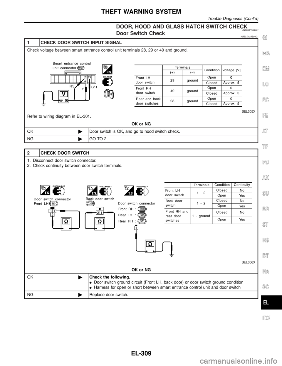
DOOR, HOOD AND GLASS HATCH SWITCH CHECK=NBEL0123S04Door Switch CheckNBEL0123S0401
1 CHECK DOOR SWITCH INPUT SIGNAL
Check voltage between smart entrance control unit terminals 28, 29 or 40 and ground.
SEL305X
Refer to wiring diagram in EL-301.
OK or NG
OK©Door switch is OK, and go to hood switch check.
NG©GO TO 2.
2 CHECK DOOR SWITCH
1. Disconnect door switch connector.
2. Check continuity between door switch terminals.
SEL306X
OK or NG
OK©Check the following.
IDoor switch ground circuit (Front LH, back door) or door switch ground condition
IHarness for open or short between smart entrance control unit and door switch
NG©Replace door switch.
GI
MA
EM
LC
EC
FE
AT
TF
PD
AX
SU
BR
ST
RS
BT
HA
SC
IDX
THEFT WARNING SYSTEM
Trouble Diagnoses (Cont'd)
EL-309
Page 1495 of 2395
Hood Switch Check=NBEL0123S0402
1 CHECK HOOD SWITCH FITTING CONDITION
OK or NG
OK©GO TO 2.
NG©Adjust installation of hood switch or hood.
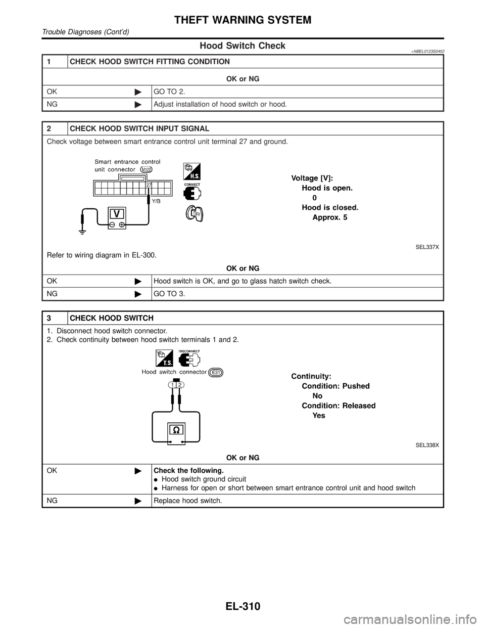
2 CHECK HOOD SWITCH INPUT SIGNAL
Check voltage between smart entrance control unit terminal 27 and ground.
SEL337X
Refer to wiring diagram in EL-300.
OK or NG
OK©Hood switch is OK, and go to glass hatch switch check.
NG©GO TO 3.
3 CHECK HOOD SWITCH
1. Disconnect hood switch connector.
2. Check continuity between hood switch terminals 1 and 2.
SEL338X
OK or NG
OK©Check the following.
IHood switch ground circuit
IHarness for open or short between smart entrance control unit and hood switch
NG©Replace hood switch.
THEFT WARNING SYSTEM
Trouble Diagnoses (Cont'd)
EL-310
Page 1509 of 2395
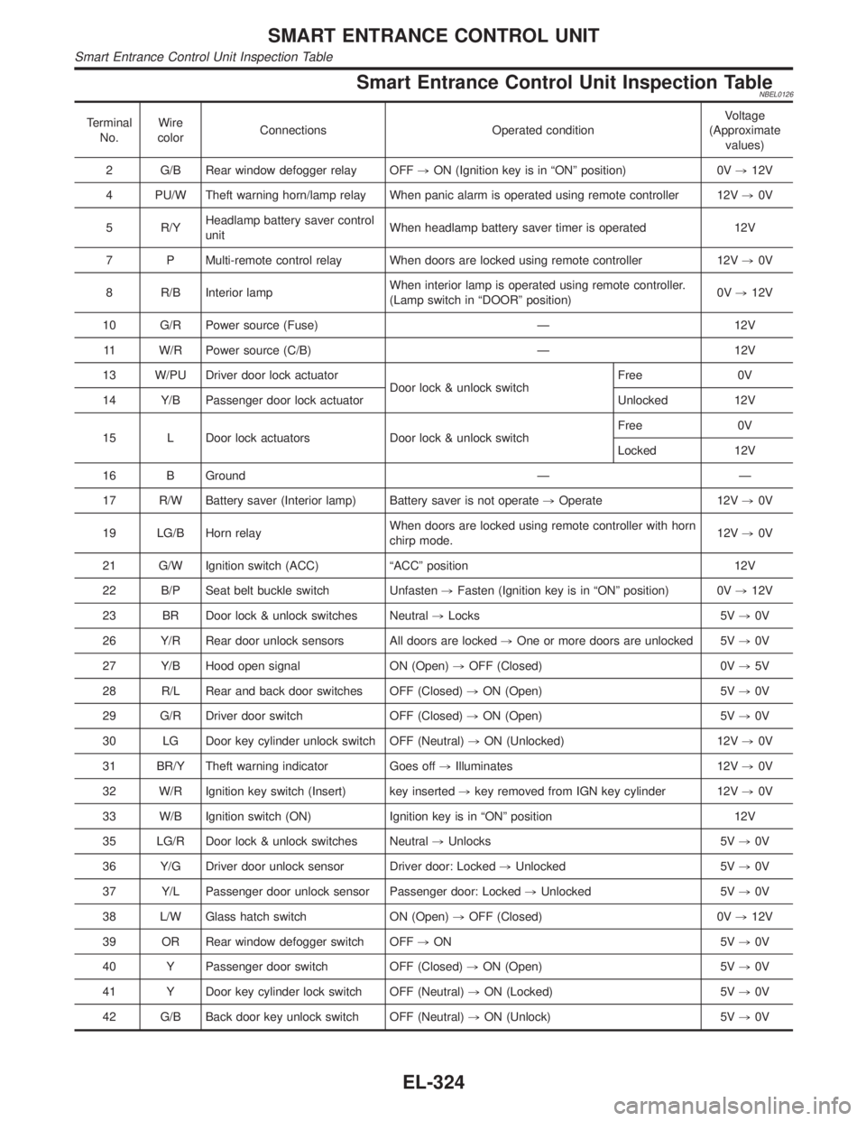
Smart Entrance Control Unit Inspection TableNBEL0126
Terminal
No.Wire
colorConnections Operated conditionVoltage
(Approximate
values)
2 G/B Rear window defogger relay OFF,ON (Ignition key is in ªONº position) 0V,12V
4 PU/W Theft warning horn/lamp relay When panic alarm is operated using remote controller 12V,0V
5 R/YHeadlamp battery saver control
unitWhen headlamp battery saver timer is operated 12V
7 P Multi-remote control relay When doors are locked using remote controller 12V,0V
8 R/B Interior lampWhen interior lamp is operated using remote controller.
(Lamp switch in ªDOORº position)0V,12V
10 G/R Power source (Fuse) Ð 12V
11 W/R Power source (C/B) Ð 12V
13 W/PU Driver door lock actuator
Door lock & unlock switchFree 0V
14 Y/B Passenger door lock actuator Unlocked 12V
15 L Door lock actuators Door lock & unlock switchFree 0V
Locked 12V
16 B Ground Ð Ð
17 R/W Battery saver (Interior lamp) Battery saver is not operate,Operate 12V,0V
19 LG/B Horn relayWhen doors are locked using remote controller with horn
chirp mode.12V,0V
21 G/W Ignition switch (ACC) ªACCº position 12V
22 B/P Seat belt buckle switch Unfasten,Fasten (Ignition key is in ªONº position) 0V,12V
23 BR Door lock & unlock switches Neutral,Locks 5V,0V
26 Y/R Rear door unlock sensors All doors are locked,One or more doors are unlocked 5V,0V
27 Y/B Hood open signal ON (Open),OFF (Closed) 0V,5V
28 R/L Rear and back door switches OFF (Closed),ON (Open) 5V,0V
29 G/R Driver door switch OFF (Closed),ON (Open) 5V,0V
30 LG Door key cylinder unlock switch OFF (Neutral),ON (Unlocked) 12V,0V
31 BR/Y Theft warning indicator Goes off,Illuminates 12V,0V
32 W/R Ignition key switch (Insert) key inserted,key removed from IGN key cylinder 12V,0V
33 W/B Ignition switch (ON) Ignition key is in ªONº position 12V
35 LG/R Door lock & unlock switches Neutral,Unlocks 5V,0V
36 Y/G Driver door unlock sensor Driver door: Locked,Unlocked 5V,0V
37 Y/L Passenger door unlock sensor Passenger door: Locked,Unlocked 5V,0V
38 L/W Glass hatch switch ON (Open),OFF (Closed) 0V,12V
39 OR Rear window defogger switch OFF,ON 5V,0V
40 Y Passenger door switch OFF (Closed),ON (Open) 5V,0V
41 Y Door key cylinder lock switch OFF (Neutral),ON (Locked) 5V,0V
42 G/B Back door key unlock switch OFF (Neutral),ON (Unlock) 5V,0V
SMART ENTRANCE CONTROL UNIT
Smart Entrance Control Unit Inspection Table
EL-324
Page 1915 of 2395
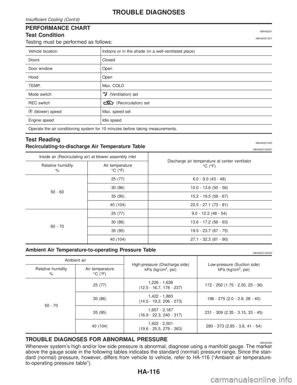
PERFORMANCE CHARTNBHA0031Test ConditionNBHA0031S01Testing must be performed as follows:
Vehicle location Indoors or in the shade (in a well-ventilated place)
Doors Closed
Door window Open
Hood Open
TEMP. Max. COLD
Mode switch
(Ventilation) set
REC switch
(Recirculation) set
(blower) speed Max. speed set
Engine speed Idle speed
Operate the air conditioning system for 10 minutes before taking measurements.
Test ReadingNBHA0031S02Recirculating-to-discharge Air Temperature TableNBHA0031S0201
Inside air (Recirculating air) at blower assembly inlet
Discharge air temperature at center ventilator
ÉC (ÉF) Relative humidity
%Air temperature
ÉC (ÉF)
50-6025 (77) 6.0 - 9.0 (43 - 48)
30 (86) 10.0 - 13.6 (50 - 56)
35 (95) 15.2 - 19.5 (59 - 67)
40 (104) 22.5 - 27.1 (73 - 81)
60-7025 (77) 9.0 - 12.2 (48 - 54)
30 (86) 13.6 - 17.2 (56 - 63)
35 (95) 19.5 - 23.7 (67 - 75)
40 (104) 27.1 - 32.3 (81 - 90)
Ambient Air Temperature-to-operating Pressure TableNBHA0031S0202
Ambient air
High-pressure (Discharge side)
kPa (kg/cm
2, psi)Low-pressure (Suction side)
kPa (kg/cm2, psi) Relative humidity
%Air temperature
ÉC (ÉF)
50-7025 (77)1,226 - 1,638
(12.5 - 16.7, 178 - 237)172 - 250 (1.75 - 2.55, 25 - 36)
30 (86)1,422 - 1,883
(14.5 - 19.2, 206 - 273)196 - 275 (2.0 - 2.8, 28 - 40)
35 (95)1,657 - 2,187
(16.9 - 22.3, 240 - 317)231 - 309 (2.35 - 3.15, 33 - 45)
40 (104)1,922 - 2,501
(19.6 - 25.5, 279 - 363)280 - 373 (2.85 - 3.8, 41 - 54)
TROUBLE DIAGNOSES FOR ABNORMAL PRESSURENBHA0032Whenever system's high and/or low side pressure is abnormal, diagnose using a manifold gauge. The marker
above the gauge scale in the following tables indicates the standard (normal) pressure range. Since the stan-
dard (normal) pressure, however, differs from vehicle to vehicle, refer to HA-116 (ªAmbient air temperature-
to-operating pressure tableº).
TROUBLE DIAGNOSES
Insufficient Cooling (Cont'd)
HA-116
Page 1964 of 2395
Fusible link ......................................................EL-16
G
Garage jack and safety stand .........................GI-46
Gauges............................................................EL-94
Generator - See Alternator .............................SC-28
Generic scan tool (GST) ................................EC-95
Glass ...............................................................BT-18
Glass hatch opener, electric .........................EL-178
Grease ............................................................MA-11
Ground distribution..........................................EL-17
H
Harness connector ............................................EL-5
Harness connector inspection .........................GI-21
Harness layout ..............................................EL-440
Hazard warning lamp ......................................EL-75
Headlamp ........................................................EL-31
Headlamp aiming control ................................EL-59
Headlining - See Roof trim .............................BT-32
Heated seat .......................................BT-43, EL-183
Height (Dimensions) ........................................GI-43
HFC134a (R134a) system precaution .............HA-2
HFC134a (R134a) system service
procedure ..................................................HA-144
HFC134a (R134a) system service tools ........HA-11
HFC134a system service equipment
precaution .....................................................HA-7
High clutch.....................................................AT-317
H/LAMP - Wiring diagram ...............................EL-36
Hood................................................................BT-12
Horn ..............................................................EL-147
HORN - Wiring diagram................................EL-147
How to erase DTC for OBD system...............EC-72
HSEAT - Wiring diagram...............................EL-183
I
IACV-AAC valve ...........................................EC-422
IATS - Wiring diagram ..................................EC-166
Identification .....................................................HA-4
Identification plate............................................GI-42
Idle air control valve (IACV) .........................EC-422
Idle mixture ratio.............................................EC-43
Idle speed .......................................................EC-43
IGN/SG - Wiring diagram .............................EC-501
Ignition control system .................................EC-499
Ignition timing .................................................EC-43
ILL - Wiring diagram .......................................EL-83
Illumination ......................................................EL-80
In vehicle sensor ..........................................HA-132
INFINITI COMMUNICATOR..........................EL-348
Infiniti communicator (IVCS) .........................EL-348
INJECT - Wiring diagram .............................EC-617
Injector ..........................................................EC-616Injector removal and installation ....................EC-41
Instrument panel .............................................BT-21
INT/L - Wiring diagram....................................EL-91
Intake air temparature sensor ......................EC-164
Intake door control linkage adjustment ..........HA-94
Intake door motor ...........................................HA-87
Intake manifold...............................................EM-12
Intake sensor ................................................HA-139
Integrated homelink transmitter ....................EL-325
Interior .............................................................BT-28
Interior lamp ....................................................EL-88
Interior lamp on-off control ..............................EL-89
Internal gear (Transfer) .................................TF-134
IVC-L - Wiring diagram.................................EC-453
IVC-R - Wiring diagram ................................EC-453
IVCS - Wiring diagram ..................................EL-359
IVCS-L - Wiring diagram ..............................EC-485
IVCS-R - Wiring diagram .............................EC-485
IVIS (Infiniti vehicle immobilizer
system) ......................................................EL-328
IVIS (Infiniti vehicle immobilizer sys-
tem) precautions ............................................GI-3
J
Jacking points ..................................................GI-45
Journal bearing assembly (propeller
shaft) .............................................................PD-9
Journal bearing disassembly (propeller
shaft) .............................................................PD-8
Junction box (J/B).........................................Foldout
K
Keyless entry system - See Multi-re-
mote control system ..................................EL-270
Knock sensor (KS) .......................................EC-328
Knuckle spindle ................................................AX-9
KS - Wiring diagram .....................................EC-330
L
Length (Dimensions) .......................................GI-43
License lamp ...................................................EL-61
Lifting points ....................................................GI-47
Limited slip diff. adjustment ............................PD-50
Limited slip diff. assembly ..............................PD-51
Limited slip diff. disassembly..........................PD-48
Limited slip diff. inspection .............................PD-49
Line pressure solenoid valve ........AT-147, 161, 167
Line pressure switch (Transfer) .....................TF-111
Line pressure test (A/T) ..................................AT-62
Liquid gasket application .................................EM-3
LOAD - Wiring diagram ................................EC-643
Location of electrical units ............................EL-436
Lock, door .......................................................BT-18
Low and reverse brake .................................AT-324
GI
MA
EM
LC
EC
FE
AT
TF
PD
AX
SU
BR
ST
RS
BT
HA
SC
EL
ALPHABETICAL INDEX
IDX-5
Page 1999 of 2395

NBMA0003
General maintenance includes those items which should be checked during the normal day-to-day operation
of the vehicle. They are essential if the vehicle is to continue operating properly. The owners can perform
checks and inspections themselves or they can have their INFINITI dealers do them.
OUTSIDE THE VEHICLE
The maintenance items listed here should be performed from time to time, unless otherwise specified.
ItemReference page
TiresCheck the pressure with a gauge periodically when at a service station,
including the spare, and adjust to the specified pressure if necessary. Check
carefully for damage, cuts or excessive wear.Ð
Wheel nutsWhen checking the tires, make sure no nuts are missing, and check for any
loose nuts. Tighten if necessary.Ð
Tire rotationTires should be rotated every 12,000 km (7,500 miles). MA-24
Wheel alignment and
balanceIf the vehicle pulls to either side while driving on a straight and level road, or
if you detect uneven or abnormal tire wear, there may be a need for wheel
alignment. If the steering wheel or seat vibrates at normal highway speeds,
wheel balancing may be needed.MA-24, SU-6, ªFront
Wheel Alignmentº
Windshield wiper
bladesCheck for cracks or wear if they do not wipe properly. Ð
Doors and engine
hoodCheck that all doors and the engine hood operate smoothly as well as the
trunk lid and back hatch. Also make sure that all latches lock securely. Lubri-
cate if necessary. Make sure that the secondary latch keeps the hood from
opening when the primary latch is released.
When driving in areas using road salt or other corrosive materials, check
lubrication frequently.MA-27
INSIDE THE VEHICLE
The maintenance items listed here should be checked on a regular basis, such as when performing periodic maintenance, cleaning the
vehicle, etc.
ItemReference page
LampsMake sure that the headlamps, stop lamps, tail lamps, turn signal lamps, and
other lamps are all operating properly and installed securely. Also check
headlamp aim.Ð
Warning lamps and
buzzers/chimesMake sure that all warning lamps and buzzers/chimes are operating properly. Ð
Windshield wiper
and washerCheck that the wipers and washer operate properly and that the wipers do
not streak.Ð
Windshield defrosterCheck that the air comes out of the defroster outlets properly and in sufficient
quantity when operating the heater or air conditioning.Ð
Steering wheelCheck that it has the specified play. Be sure to check for changes in the
steering condition, such as excessive play, hard steering or strange noises.
Free play: Less than 35 mm (1.38 in)Ð
SeatsCheck seat position controls such as seat adjusters, seatback recliner, etc. to
make sure they operate smoothly and that all latches lock securely in every
position. Check that the head restrains move up and down smoothly and that
the locks (if equipped) hold securely in all latched positions. Check that the
latches lock securely for folding-down rear seatbacks.Ð
Seat beltsCheck that all parts of the seat belt system (e.g. buckles, anchors, adjusters
and retractors) operate properly and smoothly and are installed securely.
Check the belt webbing for cuts, fraying, wear or damage.MA-28, RS-7, ªSeat Belt
Inspectionº
BrakesCheck that the brake does not pull the vehicle to one side when applied. Ð
GENERAL MAINTENANCE
MA-4