2001 INFINITI QX4 engine overheat
[x] Cancel search: engine overheatPage 723 of 2395

Possible CauseNBEC0431IHarness or connectors
(High resistance in the circuit)
IEngine coolant temperature sensor
IThermostat
SEF174Y
DTC Confirmation ProcedureNBEC0083CAUTION:
Be careful not to overheat engine.
NOTE:
If ªDTC Confirmation Procedureº has been previously conducted,
always turn ignition switch ªOFFº and wait at least 10 seconds
before conducting the next test.
WITH CONSULT-IINBEC0083S011) Turn ignition switch ªONº.
2) Select ªDATA MONITORº mode with CONSULT-II.
3) Check that ªCOOLAN TEMP/Sº is above 10ÉC (50ÉF).
If it is above 10ÉC (50ÉF), the test result will be OK.
If it is below 10ÉC (50ÉF), go to following step.
4) Start engine and run it for 65 minutes at idle speed.
If ªCOOLAN TEMP/Sº increases to more than 10ÉC (50ÉF)
within 65 minutes, stop engine because the test result will
be OK.
5) If 1st trip DTC is detected, go to ªDiagnostic Procedureº,
EC-190.
WITH GSTNBEC0083S02Follow the procedure ªWITH CONSULT-IIº above.
DTC P0125 ENGINE COOLANT TEMPERATURE SENSOR (ECTS)
Possible Cause
EC-188
Page 849 of 2395

On Board Diagnosis LogicNBEC0610This diagnosis checks whether the engine coolant temperature is
extraordinary high, even when the load is not heavy.
When malfunction is detected, the malfunction indicator lamp (MIL)
will light up even in the first trip.
Malfunction is detected when engine coolant temperature is exces-
sively high under normal engine speed.
Possible CauseNBEC0611IThermostat
IImproper ignition timing
IEngine coolant temperature sensor
IBlocked radiator
IBlocked front end (Improper fitting of nose mask)
ICrushed vehicle frontal area (Vehicle frontal is collided but not
repaired)
IBlocked air passage by improper installation of front fog lamp
or fog lamps.
IImproper mixture ratio of coolant
IDamaged bumper
For more information, refer to ªMAIN 12 CAUSES OF
OVERHEATINGº, EC-319.
Overall Function CheckNBEC0612Use this procedure to check the overall function of the coolant
overtemperature enrichment protection check, a DTC might not be
confirmed.
WARNING:
Never remove the radiator cap when the engine is hot. Serious
burns could be caused by high-pressure fluid escaping from
the radiator.
Wrap a thick cloth around the cap. Carefully remove the cap
by turning it a quarter turn to allow built-up pressure to
escape. Then turn the cap all the way off.
SEF621W
WITH CONSULT-IINBEC0612S011) Check the coolant level and mixture ratio (using coolant tester)
in the reservoir tank and radiator.
Allow engine to cool before checking coolant level and
mixture ratio.
IIf the coolant level in the reservoir and/or radiator is below the
proper range, go to ªDiagnostic Procedureº, EC-316.
IIf the coolant mixture ratio is out of the range of 45 to 55%,
replace the coolant in the following procedure MA-14, ªChang-
ing Engine Coolantº.
a) Fill radiator with coolant up to specified level with a filling speed
DTC P0217 COOLANT OVERTEMPERATURE ENRICHMENT PROTECTION
On Board Diagnosis Logic
EC-314
Page 853 of 2395

5 CHECK ENGINE COOLANT TEMPERATURE SENSOR
1. Remove engine coolant temperature sensor.
2. Check resistance between engine coolant temperature sensor terminals 1 and 2 as shown in the figure.
SEF304X
OK or NG
OK©GO TO 6.
NG©Replace engine coolant temperature sensor.
6 CHECK MAIN 12 CAUSES
If the cause cannot be isolated, go to ªMAIN 12 CAUSES OF OVERHEATINGº, EC-319.
©INSPECTION END
DTC P0217 COOLANT OVERTEMPERATURE ENRICHMENT PROTECTION
Diagnostic Procedure (Cont'd)
EC-318
Page 854 of 2395

Main 12 Causes of OverheatingNBEC0615
Engine Step Inspection item Equipment Standard Reference page
OFF 1IBlocked radiator
IBlocked condenser
IBlocked radiator grille
IBlocked bumperIVisual No blocking Ð
2ICoolant mixtureICoolant tester 50 - 50% coolant mixture See MA-11, ªRECOM-
MENDED FLUIDS AND
LUBRICANTSº.
3ICoolant levelIVisual Coolant up to MAX level
in reservoir tank and
radiator filler neckSee MA-14, ªChanging
Engine Coolantº.
4IRadiator capIPressure tester 59 - 98 kPa
(0.6 - 1.0 kg/cm
2,9-14
psi) (Limit)See LC-11, ªSystem
Checkº.
ON*
25ICoolant leaksIVisual No leaks See LC-11, ªSystem
Checkº.
ON*
26IThermostatITouch the upper and
lower radiator hosesBoth hoses should be
hotSee LC-16, ªThermostatº
and LC-19, ªRadiatorº.
ON*
17*5ICooling fanICONSULT-II Operating See trouble diagnosis for
DTC P0217 (EC-314).
OFF 8ICombustion gas leakIColor checker chemi-
cal tester 4 Gas ana-
lyzerNegative Ð
ON*
39ICoolant temperature
gaugeIVisual Gauge less than 3/4
when drivingÐ
ICoolant overflow to
reservoir tankIVisual No overflow during driv-
ing and idlingSee MA-14, ªChanging
Engine Coolantº.
OFF*
410ICoolant return from
reservoir tank to radia-
torIVisual Should be initial level in
reservoir tankSee MA-13, ªENGINE
MAINTENANCEº.
OFF 11ICylinder headIStraight gauge feeler
gauge0.1 mm (0.004 in) Maxi-
mum distortion (warping)See EM-42, ªInspectionº.
12ICylinder block and pis-
tonsIVisual No scuffing on cylinder
walls or pistonSee EM-63, ªInspectionº.
*1: Turn the ignition switch ON.
*2: Engine running at 3,000 rpm for 10 minutes.
*3: Drive at 90 km/h (55 MPH) for 30 minutes and then let idle for 10 minutes.
*4: After 60 minutes of cool down time.
*5: Cooling fan is not applied to this vehicle.
For more information, refer to LC-24, ªOVERHEATING CAUSE ANALYSISº.
GI
MA
EM
LC
FE
AT
TF
PD
AX
SU
BR
ST
RS
BT
HA
SC
EL
IDX
DTC P0217 COOLANT OVERTEMPERATURE ENRICHMENT PROTECTION
Main 12 Causes of Overheating
EC-319
Page 855 of 2395

On Board Diagnosis LogicNBEC0182When a misfire occurs, engine speed will fluctuate. If the engine
speed fluctuates enough to cause the CKP sensor signal to vary,
ECM can determine that a misfire is occurring.
Sensor Input Signal to ECM ECM function
Crankshaft position sensor (POS) Engine speed On board diagnosis of misfire
The misfire detection logic consists of the following two conditions.
1. One Trip Detection Logic (Three Way Catalyst Damage)
On the first trip that a misfire condition occurs that can dam-
age the three way catalyst (TWC) due to overheating, the MIL
will blink.
When a misfire condition occurs, the ECM monitors the CKP
sensor signal every 200 engine revolutions for a change.
When the misfire condition decreases to a level that will not
damage the TWC, the MIL will turn off.
If another misfire condition occurs that can damage the TWC
on a second trip, the MIL will blink.
When the misfire condition decreases to a level that will not
damage the TWC, the MIL will remain on.
If another misfire condition occurs that can damage the TWC,
the MIL will begin to blink again.
2. Two Trip Detection Logic (Exhaust quality deterioration)
For misfire conditions that will not damage the TWC (but will
affect vehicle emissions), the MIL will only light when the mis-
fire is detected on a second trip. During this condition, the ECM
monitors the CKP sensor signal every 1,000 engine revolu-
tions.
A misfire malfunction can be detected on any one cylinder or
on multiple cylinders.
Malfunction is detected when multiple cylinders misfire, No. 1 cyl-
inder misfires, No. 2 cylinder misfires, No. 3 cylinder misfires, No.
4 cylinder misfires, No. 5 cylinder misfires and No. 6 cylinder
misfires.
Possible CauseNBEC0490IImproper spark plug
IInsufficient compression
IIncorrect fuel pressure
IThe injector circuit is open or shorted
IInjectors
IIntake air leak
IThe ignition secondary circuit is open or shorted
ILack of fuel
IDrive plate or flywheel
IHeated oxygen sensor 1 (front)
DTC P0300 - P0306 NO.6-1CYLINDER MISFIRE, MULTIPLE CYLINDER
MISFIRE
On Board Diagnosis Logic
EC-320
Page 1916 of 2395

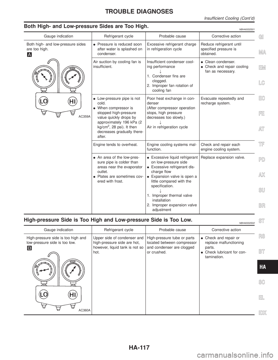
Both High- and Low-pressure Sides are Too High.NBHA0032S01
Gauge indication Refrigerant cycle Probable cause Corrective action
Both high- and low-pressure sides
are too high.
AC359A
IPressure is reduced soon
after water is splashed on
condenser.Excessive refrigerant charge
in refrigeration cycleReduce refrigerant until
specified pressure is
obtained.
Air suction by cooling fan is
insufficient.Insufficient condenser cool-
ing performance
"
1. Condenser fins are
clogged.
2. Improper fan rotation of
cooling fanIClean condenser.
ICheck and repair cooling
fan as necessary.
ILow-pressure pipe is not
cold.
IWhen compressor is
stopped high-pressure
value quickly drops by
approximately 196 kPa (2
kg/cm
2, 28 psi). It then
decreases gradually there-
after.Poor heat exchange in con-
denser
(After compressor operation
stops, high pressure
decreases too slowly.)
"
Air in refrigeration cycleEvacuate repeatedly and
recharge system.
Engine tends to overheat. Engine cooling systems mal-
function.Check and repair each
engine cooling system.
IAn area of the low-pres-
sure pipe is colder than
areas near the evaporator
outlet.
IPlates are sometimes cov-
ered with frost.IExcessive liquid refrigerant
on low-pressure side
IExcessive refrigerant dis-
charge flow
IExpansion valve is open a
little compared with the
specification.
"
1. Improper thermal valve
installation
2. Improper expansion valve
adjustmentReplace expansion valve.
High-pressure Side is Too High and Low-pressure Side is Too Low.NBHA0032S02
Gauge indication Refrigerant cycle Probable cause Corrective action
High-pressure side is too high and
low-pressure side is too low.
AC360A
Upper side of condenser and
high-pressure side are hot,
however, liquid tank is not so
hot.High-pressure tube or parts
located between compressor
and condenser are clogged
or crushed.ICheck and repair or
replace malfunctioning
parts.
ICheck lubricant for con-
tamination.
GI
MA
EM
LC
EC
FE
AT
TF
PD
AX
SU
BR
ST
RS
BT
SC
EL
IDX
TROUBLE DIAGNOSES
Insufficient Cooling (Cont'd)
HA-117
Page 1970 of 2395

ENGINE LUBRICATION &
COOLING SYSTEMS
SECTION
LC
CONTENTS
ENGINE LUBRICATION SYSTEM..................................2
Precautions ..................................................................2
LIQUID GASKET APPLICATION PROCEDURE............2
Preparation ..................................................................2
SPECIAL SERVICE TOOLS........................................2
COMMERCIAL SERVICE TOOL..................................3
Lubrication Circuit ........................................................3
Oil Pressure Check......................................................4
Oil Pump ......................................................................5
REMOVAL AND INSTALLATION.................................5
DISASSEMBLY AND ASSEMBLY................................5
OIL PUMP INSPECTION............................................6
REGULATOR VALVE INSPECTION............................6
OIL FILTER...............................................................7
Oil Cooler .....................................................................7
REMOVAL AND INSTALLATION.................................7
INSPECTION.............................................................8
Service Data and Specifications (SDS).......................8
OIL PRESSURE........................................................8
REGULATOR VALVE.................................................8
OIL PUMP.................................................................8
ENGINE COOLING SYSTEM..........................................9
Precautions ..................................................................9
LIQUID GASKET APPLICATION PROCEDURE............9
Preparation ..................................................................9
SPECIAL SERVICE TOOLS........................................9
Cooling Circuit ...........................................................10
System Check............................................................ 11
CHECKING COOLING SYSTEM HOSES................... 11
CHECKING RADIATOR............................................ 11
CHECKING RADIATOR CAP.................................... 11
CHECKING COOLING SYSTEM FOR LEAKS............12
Water Pump ...............................................................12
REMOVAL AND INSTALLATION...............................12
REMOVAL...............................................................12
INSPECTION...........................................................14
INSTALLATION........................................................14
Thermostat .................................................................16
REMOVAL AND INSTALLATION...............................16
INSPECTION...........................................................16
Water Control Valve ...................................................17
REMOVAL AND INSTALLATION...............................17
INSPECTION...........................................................18
Radiator .....................................................................19
REMOVAL AND INSTALLATION...............................19
Cooling Fan (Crankshaft driven) ...............................20
REMOVAL AND INSTALLATION...............................20
INSPECTION...........................................................20
Refilling Engine Coolant ............................................20
Radiator (Aluminum type) ..........................................21
PREPARATION.......................................................21
DISASSEMBLY........................................................21
ASSEMBLY.............................................................22
INSPECTION...........................................................23
Overheating Cause Analysis .....................................24
Service Data and Specifications (SDS).....................25
THERMOSTAT........................................................25
WATER CONTROL VALVE.......................................25
RADIATOR..............................................................25
GI
MA
EM
EC
FE
AT
TF
PD
AX
SU
BR
ST
RS
BT
HA
SC
EL
IDX
Page 1993 of 2395

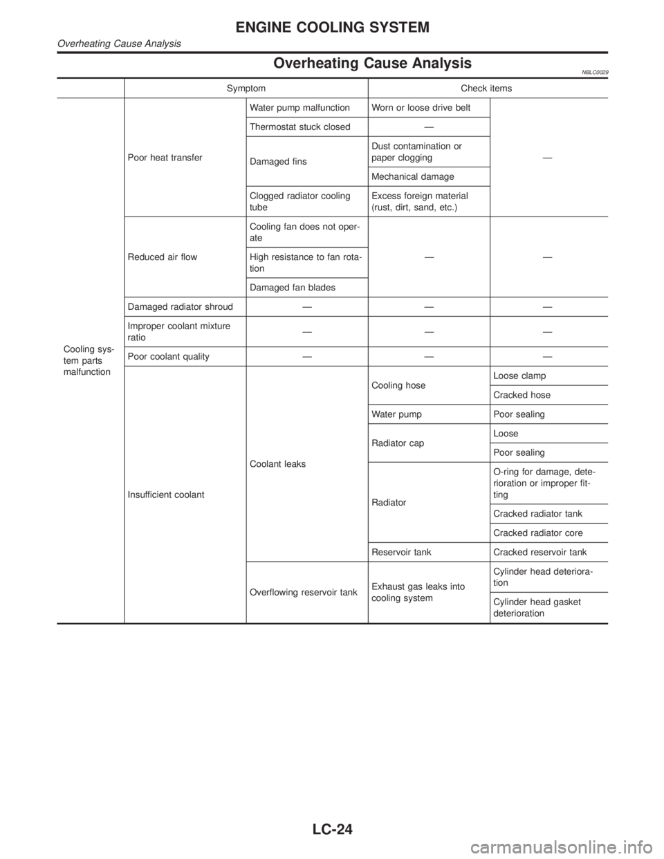
Overheating Cause AnalysisNBLC0029
Symptom Check items
Cooling sys-
tem parts
malfunctionPoor heat transferWater pump malfunction Worn or loose drive belt
Ð Thermostat stuck closed Ð
Damaged finsDust contamination or
paper clogging
Mechanical damage
Clogged radiator cooling
tubeExcess foreign material
(rust, dirt, sand, etc.)
Reduced air flowCooling fan does not oper-
ate
ÐÐ High resistance to fan rota-
tion
Damaged fan blades
Damaged radiator shroud Ð Ð Ð
Improper coolant mixture
ratioÐÐÐ
Poor coolant quality Ð Ð Ð
Insufficient coolantCoolant leaksCooling hoseLoose clamp
Cracked hose
Water pump Poor sealing
Radiator capLoose
Poor sealing
RadiatorO-ring for damage, dete-
rioration or improper fit-
ting
Cracked radiator tank
Cracked radiator core
Reservoir tank Cracked reservoir tank
Overflowing reservoir tankExhaust gas leaks into
cooling systemCylinder head deteriora-
tion
Cylinder head gasket
deterioration
ENGINE COOLING SYSTEM
Overheating Cause Analysis
LC-24