Page 2374 of 2395

SMT945C
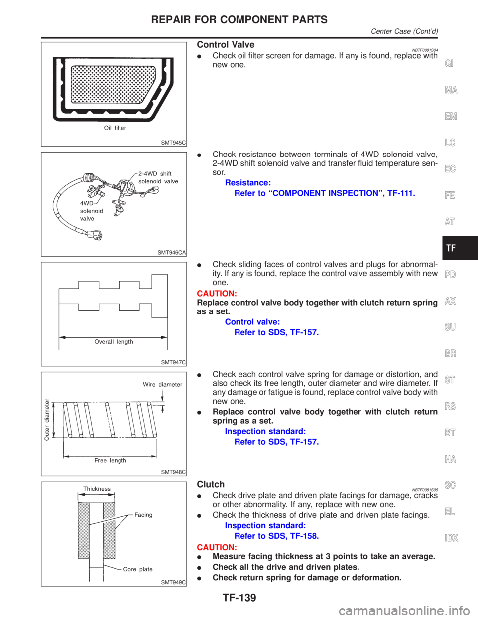
Control ValveNBTF0081S04ICheck oil filter screen for damage. If any is found, replace with
new one.
SMT946CA
ICheck resistance between terminals of 4WD solenoid valve,
2-4WD shift solenoid valve and transfer fluid temperature sen-
sor.
Resistance:
Refer to ªCOMPONENT INSPECTIONº, TF-111.
SMT947C
ICheck sliding faces of control valves and plugs for abnormal-
ity. If any is found, replace the control valve assembly with new
one.
CAUTION:
Replace control valve body together with clutch return spring
as a set.
Control valve:
Refer to SDS, TF-157.
SMT948C
ICheck each control valve spring for damage or distortion, and
also check its free length, outer diameter and wire diameter. If
any damage or fatigue is found, replace control valve body with
new one.
IReplace control valve body together with clutch return
spring as a set.
Inspection standard:
Refer to SDS, TF-157.
SMT949C
ClutchNBTF0081S05ICheck drive plate and driven plate facings for damage, cracks
or other abnormality. If any, replace with new one.
ICheck the thickness of drive plate and driven plate facings.
Inspection standard:
Refer to SDS, TF-158.
CAUTION:
IMeasure facing thickness at 3 points to take an average.
ICheck all the drive and driven plates.
ICheck return spring for damage or deformation.
GI
MA
EM
LC
EC
FE
AT
PD
AX
SU
BR
ST
RS
BT
HA
SC
EL
IDX
REPAIR FOR COMPONENT PARTS
Center Case (Cont'd)
TF-139
Page 2378 of 2395

SMT021D
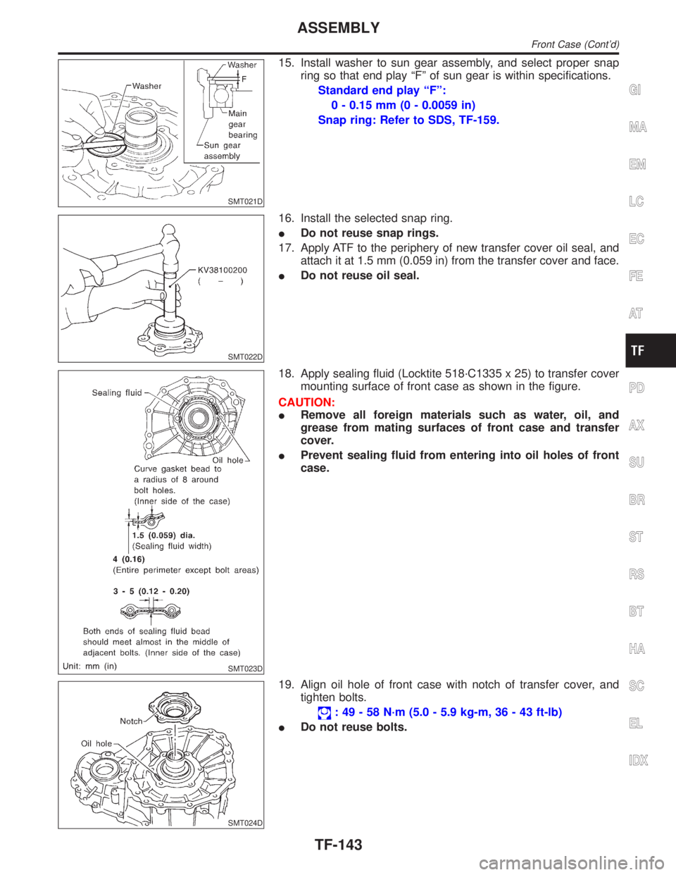
15. Install washer to sun gear assembly, and select proper snap
ring so that end play ªFº of sun gear is within specifications.
Standard end play ªFº:
0 - 0.15 mm (0 - 0.0059 in)
Snap ring: Refer to SDS, TF-159.
SMT022D
16. Install the selected snap ring.
IDo not reuse snap rings.
17. Apply ATF to the periphery of new transfer cover oil seal, and
attach it at 1.5 mm (0.059 in) from the transfer cover and face.
IDo not reuse oil seal.
SMT023D
18. Apply sealing fluid (Locktite 518´C1335 x 25) to transfer cover
mounting surface of front case as shown in the figure.
CAUTION:
IRemove all foreign materials such as water, oil, and
grease from mating surfaces of front case and transfer
cover.
IPrevent sealing fluid from entering into oil holes of front
case.
SMT024D
19. Align oil hole of front case with notch of transfer cover, and
tighten bolts.
: 49 - 58 N´m (5.0 - 5.9 kg-m, 36 - 43 ft-lb)
IDo not reuse bolts.
GI
MA
EM
LC
EC
FE
AT
PD
AX
SU
BR
ST
RS
BT
HA
SC
EL
IDX
ASSEMBLY
Front Case (Cont'd)
TF-143
Page 2381 of 2395
SMT955C
4. Align dowel pin hole and mounting bolt hole of sub-oil pump
assembly with center case. Then tighten bolts.
:7-9N´m(0.7 - 0.9 kg-m, 61 - 78 in-lb)
SMT956C
5. Apply ATF or petroleum jelly to new O-ring and install it to
transfer motor.
6. Fit double-flat end of transfer motor shaft into slot of sub-oil
pump assembly. Then tighten bolts.
: 41 - 48 N´m (4.2 - 4.9 kg-m, 30 - 35 ft-lb)
SMT957C
Main Oil PumpNBTF0083S031. Install inner gear and outer gear in the main oil pump housing
with their identification marks facing toward center case
mounting surface side. Then, measure the side clearance.
Refer to ªMain Oil Pumpº, ªCenter Caseº, TF-138.
SMT930C
2. Install main oil pump assembly to center case assembly, and
tighten bolts.
:7-9N´m(0.7 - 0.9 kg-m, 61 - 78 in-lb)
3. Install oil pump shaft to main oil pump, then install rear case
assembly to center case.
Refer to ªFinal Assemblyº, TF-153.
ASSEMBLY
Center Case (Cont'd)
TF-146
Page 2392 of 2395

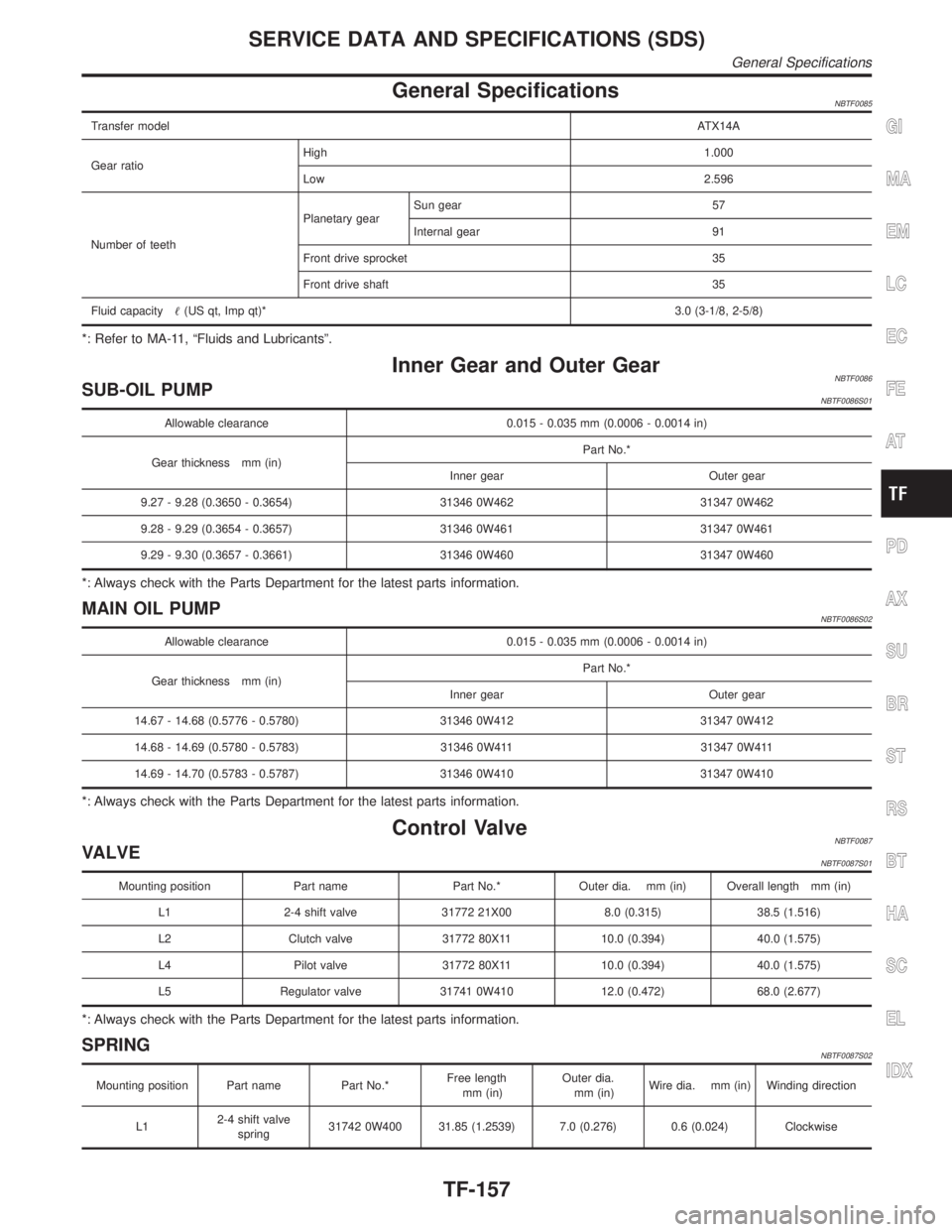
General SpecificationsNBTF0085
Transfer modelATX14A
Gear ratioHigh1.000
Low2.596
Number of teethPlanetary gearSun gear 57
Internal gear 91
Front drive sprocket 35
Front drive shaft 35
Fluid capacity(US qt, Imp qt)*3.0 (3-1/8, 2-5/8)
*: Refer to MA-11, ªFluids and Lubricantsº.
Inner Gear and Outer GearNBTF0086SUB-OIL PUMPNBTF0086S01
Allowable clearance 0.015 - 0.035 mm (0.0006 - 0.0014 in)
Gear thickness mm (in)Part No.*
Inner gear Outer gear
9.27 - 9.28 (0.3650 - 0.3654) 31346 0W462 31347 0W462
9.28 - 9.29 (0.3654 - 0.3657) 31346 0W461 31347 0W461
9.29 - 9.30 (0.3657 - 0.3661) 31346 0W460 31347 0W460
*: Always check with the Parts Department for the latest parts information.
MAIN OIL PUMPNBTF0086S02
Allowable clearance 0.015 - 0.035 mm (0.0006 - 0.0014 in)
Gear thickness mm (in)Part No.*
Inner gear Outer gear
14.67 - 14.68 (0.5776 - 0.5780) 31346 0W412 31347 0W412
14.68 - 14.69 (0.5780 - 0.5783) 31346 0W411 31347 0W411
14.69 - 14.70 (0.5783 - 0.5787) 31346 0W410 31347 0W410
*: Always check with the Parts Department for the latest parts information.
Control ValveNBTF0087VALVENBTF0087S01
Mounting position Part name Part No.* Outer dia. mm (in) Overall length mm (in)
L1 2-4 shift valve 31772 21X00 8.0 (0.315) 38.5 (1.516)
L2 Clutch valve 31772 80X11 10.0 (0.394) 40.0 (1.575)
L4 Pilot valve 31772 80X11 10.0 (0.394) 40.0 (1.575)
L5 Regulator valve 31741 0W410 12.0 (0.472) 68.0 (2.677)
*: Always check with the Parts Department for the latest parts information.
SPRINGNBTF0087S02
Mounting position Part name Part No.*Free length
mm (in)Outer dia.
mm (in)Wire dia. mm (in) Winding direction
L12-4 shift valve
spring31742 0W400 31.85 (1.2539) 7.0 (0.276) 0.6 (0.024) Clockwise
GI
MA
EM
LC
EC
FE
AT
PD
AX
SU
BR
ST
RS
BT
HA
SC
EL
IDX
SERVICE DATA AND SPECIFICATIONS (SDS)
General Specifications
TF-157