Page 2116 of 2395

SRS662
DEPLOYMENT PROCEDURES FOR SEAT BELT PRE-
TENSIONER (OUTSIDE OF VEHICLE)
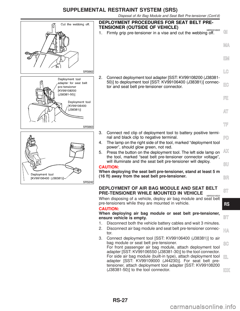
NBRS0018S051. Firmly grip pre-tensioner in a vise and cut the webbing off.
SRS663
2. Connect deployment tool adapter [SST: KV99108200 (J38381-
50)] to deployment tool [SST: KV99106400 (J38381)] connec-
tor and seat belt pre-tensioner connector.
SRS242
3. Connect red clip of deployment tool to battery positive termi-
nal and black clip to negative terminal.
4. The lamp on the right side of the tool, marked ªdeployment tool
powerº, should glow green, not red.
5. Press the button on the deployment tool. The left side lamp on
the tool, marked ªseat belt pre-tensioner connector voltageº,
will illuminate and the seat belt pre-tensioner will deploy.
CAUTION:
When deploying the seat belt pre-tensioner, stand at least 5 m
(16 ft) away from the seat belt pre-tensioner.
DEPLOYMENT OF AIR BAG MODULE AND SEAT BELT
PRE-TENSIONER WHILE MOUNTED IN VEHICLE
NBRS0018S03When disposing of a vehicle, deploy air bag module and seat belt
pre-tensioners while they are mounted in vehicle.
CAUTION:
When deploying air bag module or seat belt pre-tensioner,
ensure vehicle is empty.
1. Disconnect both the vehicle battery cables and wait 3 minutes.
2. Disconnect air bag module and seat belt pre-tensioner connec-
tor.
3. Connect deployment tool [SST: KV99106400 (J38381)] to air
bag module or seat belt pre-tensioner.
For front passenger air bag module, attach deployment tool
adapter [SST: KV991065S0 (J38381-30)] to the tool connector.
For side air bag module (built-in type), attach deployment tool
adapter [SST: KV99109000 (J44230)]. For seat belt pre-
tensioner, attach deployment tool adapter [SST: KV99108200
(J38381-50)] to the tool connector.
GI
MA
EM
LC
EC
FE
AT
TF
PD
AX
SU
BR
ST
BT
HA
SC
EL
IDX
SUPPLEMENTAL RESTRAINT SYSTEM (SRS)
Disposal of Air Bag Module and Seat Belt Pre-tensioner (Cont'd)
RS-27
Page 2118 of 2395

Trouble Diagnoses Introduction=NBRS0040CAUTION:
IDo not use electrical test equipment on any circuit related to the SRS unless instructed to in this
Service Manual. Spiral cable and wiring harnesses covered with yellow insulation tape either just
before the harness connectors or for the complete harness are related to the SRS.
IDo not attempt to repair, splice or modify the SRS wiring harness. If the harness is damaged,
replace it with a new one.
IKeep ground portion clean.
DIAGNOSIS FUNCTIONNBRS0040S01The SRS self-diagnosis results can be read by using ªAIR BAGº warning lamp and/or CONSULT-II. The read-
ing of these results is accomplished using one of two modes Ð ªUser modeº and ªDiagnosis modeº.
The User mode is exclusively prepared for the customer (driver). This mode warns the driver of a system
malfunction through the operation of the ªAIR BAGº warning lamp.
The Diagnosis mode allows the technician to locate and inspect the malfunctioning part.
The mode applications for the ªAIR BAGº warning lamp and CONSULT-II are as follows:
User mode Diagnosis mode Display type
ªAIR BAGº warning lamp X X ON-OFF operation
CONSULT-II Ð X Monitoring
NOTE:
Seat belt pre-tensioner malfunction is indicated by ªAIR BAGº warning lamp.
DIAGNOSIS MODE FOR CONSULT-IINBRS0040S02IªSELF-DIAG [CURRENT]º
A current Self-diagnosis result (also indicated by the number of warning lamp flashes in the Diagnosis
mode) is displayed on the CONSULT-II screen in real time. This refers to a malfunctioning part requiring
repairs.
IªSELF-DIAG [PAST]º
Diagnosis results previously stored in the memory are displayed on the CONSULT-II screen. The stored
results are not erased until memory erasing is executed.
IªTROUBLE DIAG RECORDº
With TROUBLE DIAG RECORD, diagnosis results previously erased by a reset operation can be displayed
on the CONSULT-II screen.
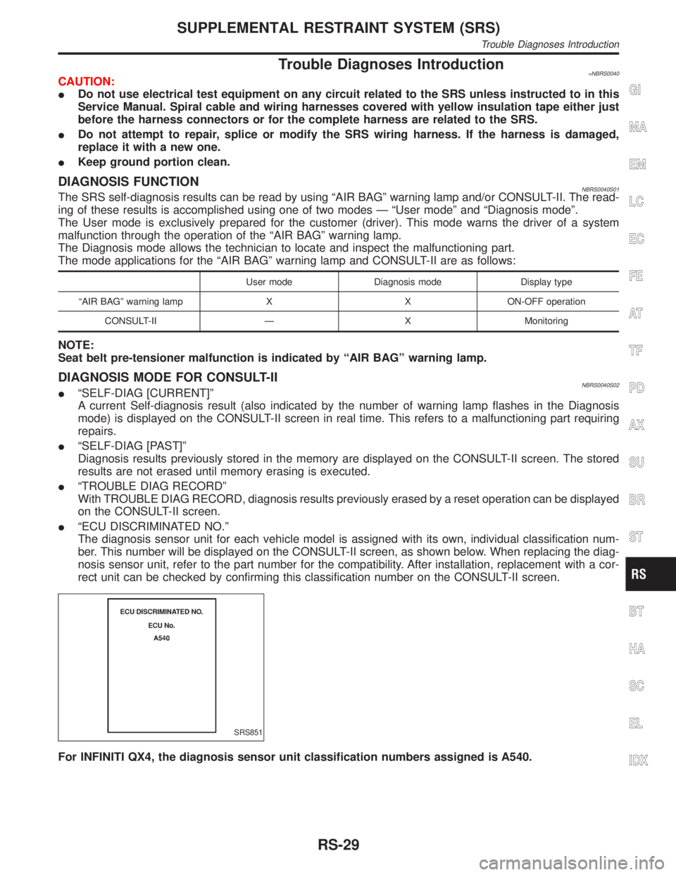
IªECU DISCRIMINATED NO.º
The diagnosis sensor unit for each vehicle model is assigned with its own, individual classification num-
ber. This number will be displayed on the CONSULT-II screen, as shown below. When replacing the diag-
nosis sensor unit, refer to the part number for the compatibility. After installation, replacement with a cor-
rect unit can be checked by confirming this classification number on the CONSULT-II screen.
SRS851
For INFINITI QX4, the diagnosis sensor unit classification numbers assigned is A540.
GI
MA
EM
LC
EC
FE
AT
TF
PD
AX
SU
BR
ST
BT
HA
SC
EL
IDX
SUPPLEMENTAL RESTRAINT SYSTEM (SRS)
Trouble Diagnoses Introduction
RS-29
Page 2120 of 2395
After the malfunction is repaired completely, no malfunction is detected on ªSELF-DIAG [CURRENT]º.
IªSELF-DIAG [PAST]º
Return to the ªSELF-DIAG [CURRENT]º CONSULT-II screen by pushing ªBACKº key of CONSULT-II and
select ªSELF-DIAG [CURRENT]º in SELECT DIAG MODE. Touch ªERASEº in ªSELF-DIAG [CURRENT]º
mode.
NOTE:
If the memory of the malfunction in ªSELF-DIAG [PAST]º is not erased, the User mode shows the sys-
tem malfunction by the operation of the warning lamp even if the malfunction is repaired completely.
SRS701
IªTROUBLE DIAG RECORDº
The memory of ªTROUBLE DIAG RECORDº cannot be erased.
Without CONSULT-IINBRS0040S0502After a malfunction is repaired, switch the ignition ªOFFº for at least one second, then back ªONº. Diagnosis
mode returns to the User mode. At that time, the self-diagnostic result is cleared.
GI
MA
EM
LC
EC
FE
AT
TF
PD
AX
SU
BR
ST
BT
HA
SC
EL
IDX
SUPPLEMENTAL RESTRAINT SYSTEM (SRS)
Trouble Diagnoses Introduction (Cont'd)
RS-31
Page 2122 of 2395
WORK FLOW=NBRS0041S03NOTE:
Seat belt pre-tensioner malfunction is indicated by ªAIR BAGº warning lamp.
SRS799
*1: RS-32
*2: RS-38*3: RS-39
*4: RS-48*5: RS-42
*6: RS-53
GI
MA
EM
LC
EC
FE
AT
TF
PD
AX
SU
BR
ST
BT
HA
SC
EL
IDX
SUPPLEMENTAL RESTRAINT SYSTEM (SRS)
How to Perform Trouble Diagnoses for Quick and Accurate Repair (Cont'd)
RS-33
Page 2124 of 2395
Wiring Diagram Ð SRS ÐNBRS0043
MRS326A
GI
MA
EM
LC
EC
FE
AT
TF
PD
AX
SU
BR
ST
BT
HA
SC
EL
IDX
SUPPLEMENTAL RESTRAINT SYSTEM (SRS)
Wiring Diagram Ð SRS Ð
RS-35
Page 2126 of 2395
MRS327A
GI
MA
EM
LC
EC
FE
AT
TF
PD
AX
SU
BR
ST
BT
HA
SC
EL
IDX
SUPPLEMENTAL RESTRAINT SYSTEM (SRS)
Wiring Diagram Ð SRS Ð (Cont'd)
RS-37
Page 2128 of 2395
SRS844
Trouble Diagnoses with CONSULT-II=NBRS0045DIAGNOSTIC PROCEDURE 2NBRS0045S01Inspecting SRS malfunctioning parts by using CONSULT-II Ð
Diagnosis mode
1. Turn ignition switch ªOFFº.
2. Connect CONSULT-II to data link connector.
SRS695
3. Turn ignition switch ªONº.
4. Touch ªSTARTº.
SRS771
5. Touch ªAIR BAGº.
SRS697
6. Touch ªSELF-DIAG [CURRENT]º.
SRS772
7. Diagnostic codes are displayed on ªSELF-DIAG [CURRENT]º.
GI
MA
EM
LC
EC
FE
AT
TF
PD
AX
SU
BR
ST
BT
HA
SC
EL
IDX
SUPPLEMENTAL RESTRAINT SYSTEM (SRS)
Trouble Diagnoses with CONSULT-II
RS-39
Page 2130 of 2395
![INFINITI QX4 2001 Factory Service Manual Diagnostic item ExplanationRepair order
ªRecheck SRS at each replace-
ment.º
AIRBAG MODULE
[VB-SHORT]IDrivers air bag module circuit is shorted to some power sup-
ply circuit. (including the spiral INFINITI QX4 2001 Factory Service Manual Diagnostic item ExplanationRepair order
ªRecheck SRS at each replace-
ment.º
AIRBAG MODULE
[VB-SHORT]IDrivers air bag module circuit is shorted to some power sup-
ply circuit. (including the spiral](/manual-img/42/57027/w960_57027-2129.png)
Diagnostic item ExplanationRepair order
ªRecheck SRS at each replace-
ment.º
AIRBAG MODULE
[VB-SHORT]IDriver's air bag module circuit is shorted to some power sup-
ply circuit. (including the spiral cable)1. Visually check the wiring harness
connection.
2. Replace the harness if it has visible
damage.
3. Replace the spiral cable.
4. Replace driver's air bag module.
(Before disposal of it, it must be
deployed.)
5. Replace the diagnosis sensor unit.
6. Replace the related harness. AIRBAG MODULE
[GND-SHORT]IDriver's air bag module circuit is shorted to ground. (including
the spiral cable)
AIRBAG MODULE
[SHORT]IDriver's air bag module circuits are shorted to each other.
ASSIST A/B MODULE
[VB-SHORT]IFront passenger air bag module circuit is shorted to some
power supply circuit.1. Visually check the wiring harness
connection.
2. Replace the harness if it has visible
damage.
3. Replace front passenger air bag
module. (Before disposal of it, it
must be deployed.)
4. Replace the diagnosis sensor unit.
5. Replace the related harness. ASSIST A/B MODULE
[OPEN]IFront passenger air bag module circuit is open.
ASSIST A/B MODULE
[GND-SHORT]IFront passenger air bag module circuit is shorted to ground.
ASSIST A/B MODULE
[SHORT]IFront passenger air bag module circuits are shorted to each
other.
SIDE MODULE LH
[OPEN]ISide air bag module (LH) circuit is open. 1. Visually check the wiring harness
connection.
2. Replace the harness if it has visible
damage.
3. Replace side air bag module (LH).
(Before disposal, it must be
deployed.)
4. Replace the diagnosis sensor unit.
5. Replace the related harness. SIDE MODULE LH
[VB-SHORT]ISide air bag module (LH) circuit is shorted to some power
supply circuits.
SIDE MODULE LH
[GND-SHORT]ISide air bag module (LH) circuit is shorted to ground.
SIDE MODULE LH
[SHORT]ISide air bag module (LH) circuits are shorted to each other.
SIDE MODULE RH
[OPEN]ISide air bag module (RH) circuit is open. 1. Visually check the wiring harness
connection.
2. Replace the harness if it has visible
damage.
3. Replace side air bag module (RH).
(Before disposal, it must be
deployed.)
4. Replace the diagnosis sensor unit.
5. Replace the related harness. SIDE MODULE RH
[VB-SHORT]ISide air bag module (RH) circuit is shorted to some power
supply circuits.
SIDE MODULE RH
[GND-SHORT]ISide air bag module (RH) circuit is shorted to ground.
SIDE MODULE RH
[SHORT]ISide air bag module (RH) circuits are shorted to each other.
SATELLITE SENS LH
[UNIT FAIL]
SATELLITE SENS LH
[COMM FAIL]ISatellite sensor (LH) 1. Visually check the wiring harness
connection.
2. Replace the harness if it has visible
damage.
3. Replace the satellite sensor (LH).
4. Replace the diagnosis sensor unit.
5. Replace the related harness.
SATELLITE SENS RH
[UNIT FAIL]
SATELLITE SENS RH
[COMM FAIL]ISatellite sensor (RH) 1. Visually check the wiring harness
connection.
2. Replace the harness if it has visible
damage.
3. Replace the satellite sensor (RH).
4. Replace the diagnosis sensor unit.
5. Replace the related harness.GI
MA
EM
LC
EC
FE
AT
TF
PD
AX
SU
BR
ST
BT
HA
SC
EL
IDX
SUPPLEMENTAL RESTRAINT SYSTEM (SRS)
Trouble Diagnoses with CONSULT-II (Cont'd)
RS-41