2001 INFINITI QX4 relay
[x] Cancel search: relayPage 1502 of 2395

4 CHECK HORN RELAY CIRCUIT
1. Disconnect horn relay connector.
2. Check voltage between terminals 3 and 5.
3. Check voltage between terminals 6 and 7.
SEL348X
OK or NG
OK©Check harness for open or short between horn relay and smart entrance control unit.
NG©Check harness for open or short.
GI
MA
EM
LC
EC
FE
AT
TF
PD
AX
SU
BR
ST
RS
BT
HA
SC
IDX
THEFT WARNING SYSTEM
Trouble Diagnoses (Cont'd)
EL-317
Page 1503 of 2395

THEFT WARNING HEADLAMP ALARM CHECK=NBEL0123S10
1 CHECK THEFT WARNING HEADLAMP ALARM OPERATION
1. Disconnect smart entrance control unit connector.
2. Apply ground to smart entrance control unit terminal 4.
SEL570X
Refer to wiring diagram in EL-304.
OK or NG
OK©Headlamp alarm is OK.
NG©GO TO 2.
2 CHECK HEADLAMP OPERATION
Does headlamp come on when turning lighting switch ªONº?
Ye s©Check harness for open or short between headlamp relay and smart entrance control
unit.
No©Check headlamp system. Refer to ªHEADLAMPº.
THEFT WARNING SYSTEM
Trouble Diagnoses (Cont'd)
EL-318
Page 1504 of 2395
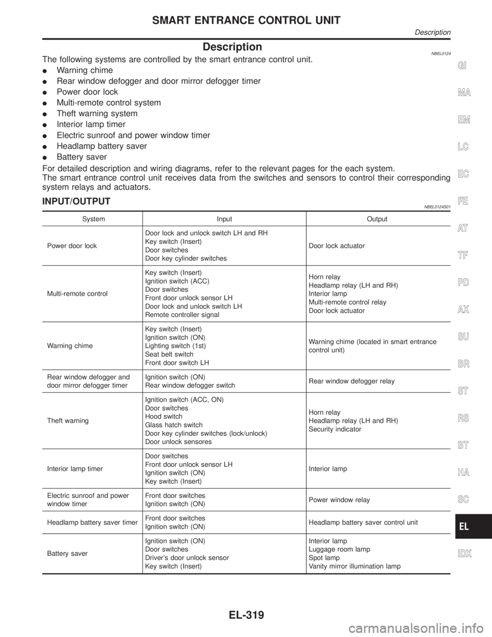
DescriptionNBEL0124The following systems are controlled by the smart entrance control unit.
IWarning chime
IRear window defogger and door mirror defogger timer
IPower door lock
IMulti-remote control system
ITheft warning system
IInterior lamp timer
IElectric sunroof and power window timer
IHeadlamp battery saver
IBattery saver
For detailed description and wiring diagrams, refer to the relevant pages for the each system.
The smart entrance control unit receives data from the switches and sensors to control their corresponding
system relays and actuators.
INPUT/OUTPUTNBEL0124S01
System Input Output
Power door lockDoor lock and unlock switch LH and RH
Key switch (Insert)
Door switches
Door key cylinder switchesDoor lock actuator
Multi-remote controlKey switch (Insert)
Ignition switch (ACC)
Door switches
Front door unlock sensor LH
Door lock and unlock switch LH
Remote controller signalHorn relay
Headlamp relay (LH and RH)
Interior lamp
Multi-remote control relay
Door lock actuator
Warning chimeKey switch (Insert)
Ignition switch (ON)
Lighting switch (1st)
Seat belt switch
Front door switch LHWarning chime (located in smart entrance
control unit)
Rear window defogger and
door mirror defogger timerIgnition switch (ON)
Rear window defogger switchRear window defogger relay
Theft warningIgnition switch (ACC, ON)
Door switches
Hood switch
Glass hatch switch
Door key cylinder switches (lock/unlock)
Door unlock sensoresHorn relay
Headlamp relay (LH and RH)
Security indicator
Interior lamp timerDoor switches
Front door unlock sensor LH
Ignition switch (ON)
Key switch (Insert)Interior lamp
Electric sunroof and power
window timerFront door switches
Ignition switch (ON)Power window relay
Headlamp battery saver timerFront door switches
Ignition switch (ON)Headlamp battery saver control unit
Battery saverIgnition switch (ON)
Door switches
Driver's door unlock sensor
Key switch (Insert)Interior lamp
Luggage room lamp
Spot lamp
Vanity mirror illumination lamp
GI
MA
EM
LC
EC
FE
AT
TF
PD
AX
SU
BR
ST
RS
BT
HA
SC
IDX
SMART ENTRANCE CONTROL UNIT
Description
EL-319
Page 1509 of 2395
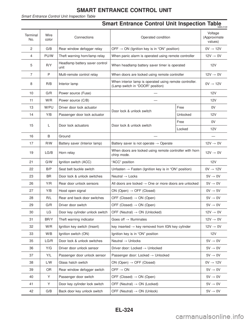
Smart Entrance Control Unit Inspection TableNBEL0126
Terminal
No.Wire
colorConnections Operated conditionVoltage
(Approximate
values)
2 G/B Rear window defogger relay OFF,ON (Ignition key is in ªONº position) 0V,12V
4 PU/W Theft warning horn/lamp relay When panic alarm is operated using remote controller 12V,0V
5 R/YHeadlamp battery saver control
unitWhen headlamp battery saver timer is operated 12V
7 P Multi-remote control relay When doors are locked using remote controller 12V,0V
8 R/B Interior lampWhen interior lamp is operated using remote controller.
(Lamp switch in ªDOORº position)0V,12V
10 G/R Power source (Fuse) Ð 12V
11 W/R Power source (C/B) Ð 12V
13 W/PU Driver door lock actuator
Door lock & unlock switchFree 0V
14 Y/B Passenger door lock actuator Unlocked 12V
15 L Door lock actuators Door lock & unlock switchFree 0V
Locked 12V
16 B Ground Ð Ð
17 R/W Battery saver (Interior lamp) Battery saver is not operate,Operate 12V,0V
19 LG/B Horn relayWhen doors are locked using remote controller with horn
chirp mode.12V,0V
21 G/W Ignition switch (ACC) ªACCº position 12V
22 B/P Seat belt buckle switch Unfasten,Fasten (Ignition key is in ªONº position) 0V,12V
23 BR Door lock & unlock switches Neutral,Locks 5V,0V
26 Y/R Rear door unlock sensors All doors are locked,One or more doors are unlocked 5V,0V
27 Y/B Hood open signal ON (Open),OFF (Closed) 0V,5V
28 R/L Rear and back door switches OFF (Closed),ON (Open) 5V,0V
29 G/R Driver door switch OFF (Closed),ON (Open) 5V,0V
30 LG Door key cylinder unlock switch OFF (Neutral),ON (Unlocked) 12V,0V
31 BR/Y Theft warning indicator Goes off,Illuminates 12V,0V
32 W/R Ignition key switch (Insert) key inserted,key removed from IGN key cylinder 12V,0V
33 W/B Ignition switch (ON) Ignition key is in ªONº position 12V
35 LG/R Door lock & unlock switches Neutral,Unlocks 5V,0V
36 Y/G Driver door unlock sensor Driver door: Locked,Unlocked 5V,0V
37 Y/L Passenger door unlock sensor Passenger door: Locked,Unlocked 5V,0V
38 L/W Glass hatch switch ON (Open),OFF (Closed) 0V,12V
39 OR Rear window defogger switch OFF,ON 5V,0V
40 Y Passenger door switch OFF (Closed),ON (Open) 5V,0V
41 Y Door key cylinder lock switch OFF (Neutral),ON (Locked) 5V,0V
42 G/B Back door key unlock switch OFF (Neutral),ON (Unlock) 5V,0V
SMART ENTRANCE CONTROL UNIT
Smart Entrance Control Unit Inspection Table
EL-324
Page 1562 of 2395
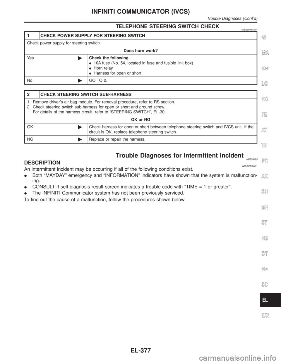
TELEPHONE STEERING SWITCH CHECK=NBEL0184S14
1 CHECK POWER SUPPLY FOR STEERING SWITCH
Check power supply for steering switch.
Does horn work?
Ye s©Check the following.
I10A fuse (No. 54, located in fuse and fusible link box)
IHorn relay
IHarness for open or short
No©GO TO 2.
2 CHECK STEERING SWITCH SUB-HARNESS
1. Remove driver's air bag module. For removal procedure, refer to RS section.
2. Check steering switch sub-harness for open or short and ground screw.
For details of the harness circuit, refer to ªSTEERING SWITCHº, EL-30.
OK or NG
OK©Check harness for open or short between telephone steering switch and IVCS unit. If the
circuit is OK, replace telephone steering switch.
NG©Replace or repair the harness.
Trouble Diagnoses for Intermittent IncidentNBEL0185DESCRIPTIONNBEL0185S01An intermittent incident may be occurring if all of the following conditions exist.
IBoth ªMAYDAYº emergency and ªINFORMATIONº indicators have shown that the system is malfunction-
ing.
ICONSULT-II self-diagnosis result screen indicates a trouble code with ªTIME=1orgreaterº.
IThe INFINITI Communicator system has not been previously serviced.
To find out the cause of a malfunction, follow the procedures shown below.
GI
MA
EM
LC
EC
FE
AT
TF
PD
AX
SU
BR
ST
RS
BT
HA
SC
IDX
INFINITI COMMUNICATOR (IVCS)
Trouble Diagnoses (Cont'd)
EL-377
Page 1625 of 2395
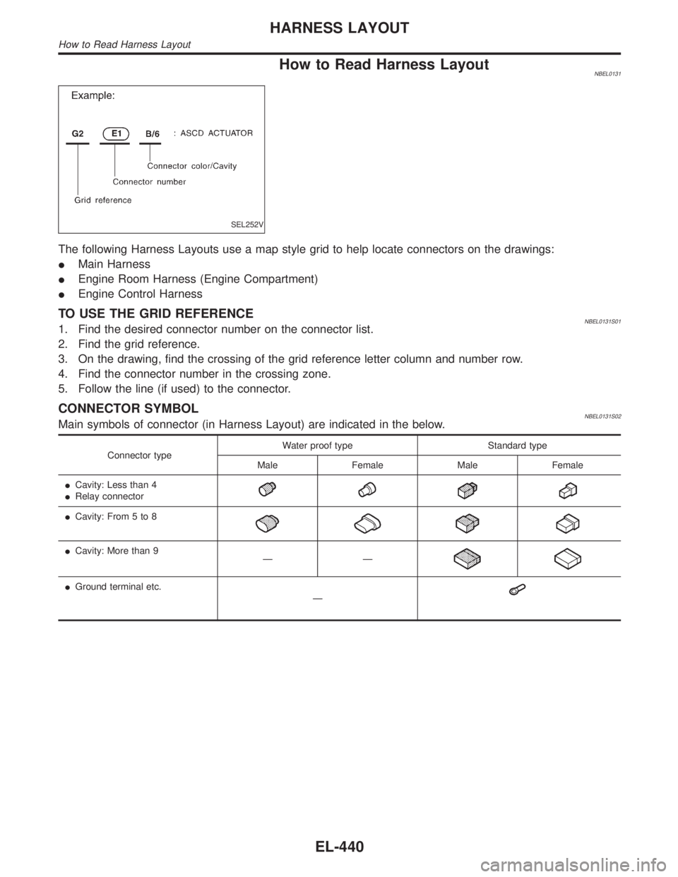
How to Read Harness LayoutNBEL0131
SEL252V
The following Harness Layouts use a map style grid to help locate connectors on the drawings:
IMain Harness
IEngine Room Harness (Engine Compartment)
IEngine Control Harness
TO USE THE GRID REFERENCENBEL0131S011. Find the desired connector number on the connector list.
2. Find the grid reference.
3. On the drawing, find the crossing of the grid reference letter column and number row.
4. Find the connector number in the crossing zone.
5. Follow the line (if used) to the connector.
CONNECTOR SYMBOLNBEL0131S02Main symbols of connector (in Harness Layout) are indicated in the below.
Connector typeWater proof type Standard type
Male Female Male Female
ICavity: Less than 4
IRelay connector
ICavity: From 5 to 8
ICavity: More than 9
ÐÐ
IGround terminal etc.
Ð
HARNESS LAYOUT
How to Read Harness Layout
EL-440
Page 1758 of 2395
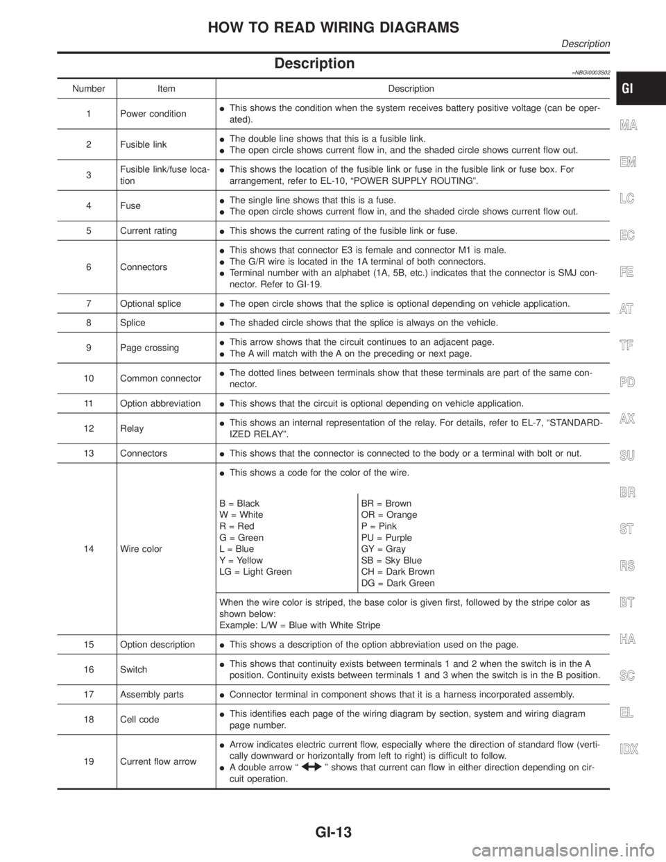
Description=NBGI0003S02
Number Item Description
1 Power conditionIThis shows the condition when the system receives battery positive voltage (can be oper-
ated).
2 Fusible linkIThe double line shows that this is a fusible link.
IThe open circle shows current flow in, and the shaded circle shows current flow out.
3Fusible link/fuse loca-
tionIThis shows the location of the fusible link or fuse in the fusible link or fuse box. For
arrangement, refer to EL-10, ªPOWER SUPPLY ROUTINGº.
4 FuseIThe single line shows that this is a fuse.
IThe open circle shows current flow in, and the shaded circle shows current flow out.
5 Current ratingIThis shows the current rating of the fusible link or fuse.
6 ConnectorsIThis shows that connector E3 is female and connector M1 is male.
IThe G/R wire is located in the 1A terminal of both connectors.
ITerminal number with an alphabet (1A, 5B, etc.) indicates that the connector is SMJ con-
nector. Refer to GI-19.
7 Optional spliceIThe open circle shows that the splice is optional depending on vehicle application.
8 SpliceIThe shaded circle shows that the splice is always on the vehicle.
9 Page crossingIThis arrow shows that the circuit continues to an adjacent page.
IThe A will match with the A on the preceding or next page.
10 Common connectorIThe dotted lines between terminals show that these terminals are part of the same con-
nector.
11 Option abbreviationIThis shows that the circuit is optional depending on vehicle application.
12 RelayIThis shows an internal representation of the relay. For details, refer to EL-7, ªSTANDARD-
IZED RELAYº.
13 ConnectorsIThis shows that the connector is connected to the body or a terminal with bolt or nut.
14 Wire colorIThis shows a code for the color of the wire.
B = Black
W = White
R = Red
G = Green
L = Blue
Y = Yellow
LG = Light GreenBR = Brown
OR = Orange
P = Pink
PU = Purple
GY = Gray
SB = Sky Blue
CH = Dark Brown
DG = Dark Green
When the wire color is striped, the base color is given first, followed by the stripe color as
shown below:
Example: L/W = Blue with White Stripe
15 Option descriptionIThis shows a description of the option abbreviation used on the page.
16 SwitchIThis shows that continuity exists between terminals 1 and 2 when the switch is in the A
position. Continuity exists between terminals 1 and 3 when the switch is in the B position.
17 Assembly partsIConnector terminal in component shows that it is a harness incorporated assembly.
18 Cell codeIThis identifies each page of the wiring diagram by section, system and wiring diagram
page number.
19 Current flow arrowIArrow indicates electric current flow, especially where the direction of standard flow (verti-
cally downward or horizontally from left to right) is difficult to follow.
IA double arrow ª
º shows that current can flow in either direction depending on cir-
cuit operation.
MA
EM
LC
EC
FE
AT
TF
PD
AX
SU
BR
ST
RS
BT
HA
SC
EL
IDX
HOW TO READ WIRING DIAGRAMS
Description
GI-13
Page 1770 of 2395
Incident Simulation TestsNBGI0004S02INTRODUCTIONNBGI0004S0201Sometimes the symptom is not present when the vehicle is brought
in for service. If possible, re-create the conditions present at the
time of the incident. Doing so may help avoid a No Trouble Found
Diagnosis. The following section illustrates ways to simulate the
conditions/environment under which the owner experiences an
electrical incident.
The section is broken into the six following topics:
IVehicle vibration
IHeat sensitive
IFreezing
IWater intrusion
IElectrical load
ICold or hot start up
Get a thorough description of the incident from the customer. It is
important for simulating the conditions of the problem.
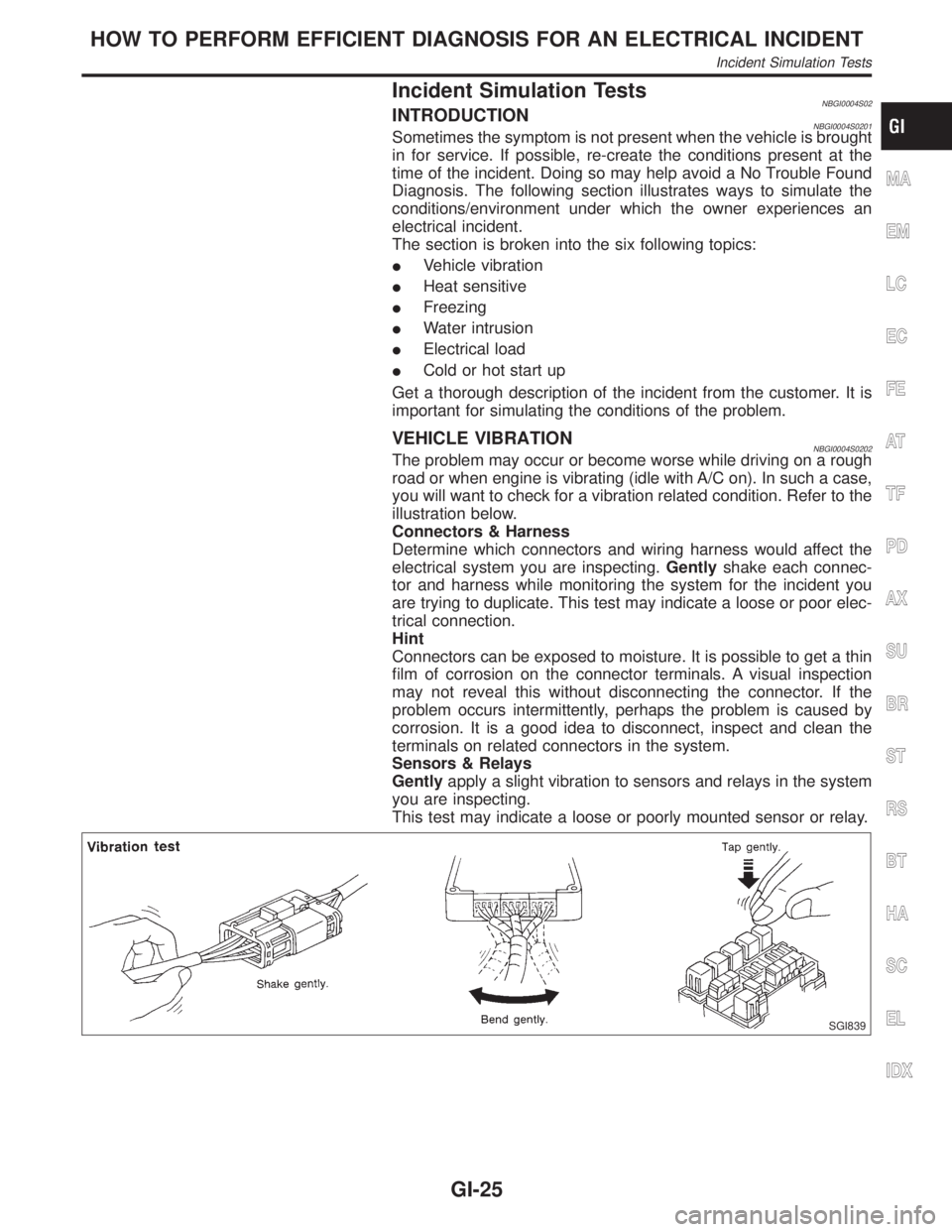
VEHICLE VIBRATIONNBGI0004S0202The problem may occur or become worse while driving on a rough
road or when engine is vibrating (idle with A/C on). In such a case,
you will want to check for a vibration related condition. Refer to the
illustration below.
Connectors & Harness
Determine which connectors and wiring harness would affect the
electrical system you are inspecting.Gentlyshake each connec-
tor and harness while monitoring the system for the incident you
are trying to duplicate. This test may indicate a loose or poor elec-
trical connection.
Hint
Connectors can be exposed to moisture. It is possible to get a thin
film of corrosion on the connector terminals. A visual inspection
may not reveal this without disconnecting the connector. If the
problem occurs intermittently, perhaps the problem is caused by
corrosion. It is a good idea to disconnect, inspect and clean the
terminals on related connectors in the system.
Sensors & Relays
Gentlyapply a slight vibration to sensors and relays in the system
you are inspecting.
This test may indicate a loose or poorly mounted sensor or relay.
SGI839
MA
EM
LC
EC
FE
AT
TF
PD
AX
SU
BR
ST
RS
BT
HA
SC
EL
IDX
HOW TO PERFORM EFFICIENT DIAGNOSIS FOR AN ELECTRICAL INCIDENT
Incident Simulation Tests
GI-25