2001 INFINITI QX4 relay
[x] Cancel search: relayPage 1773 of 2395
NOTE:
Refer to ªHOW TO CHECK TERMINALº in GI-21 to probe or
check terminal.
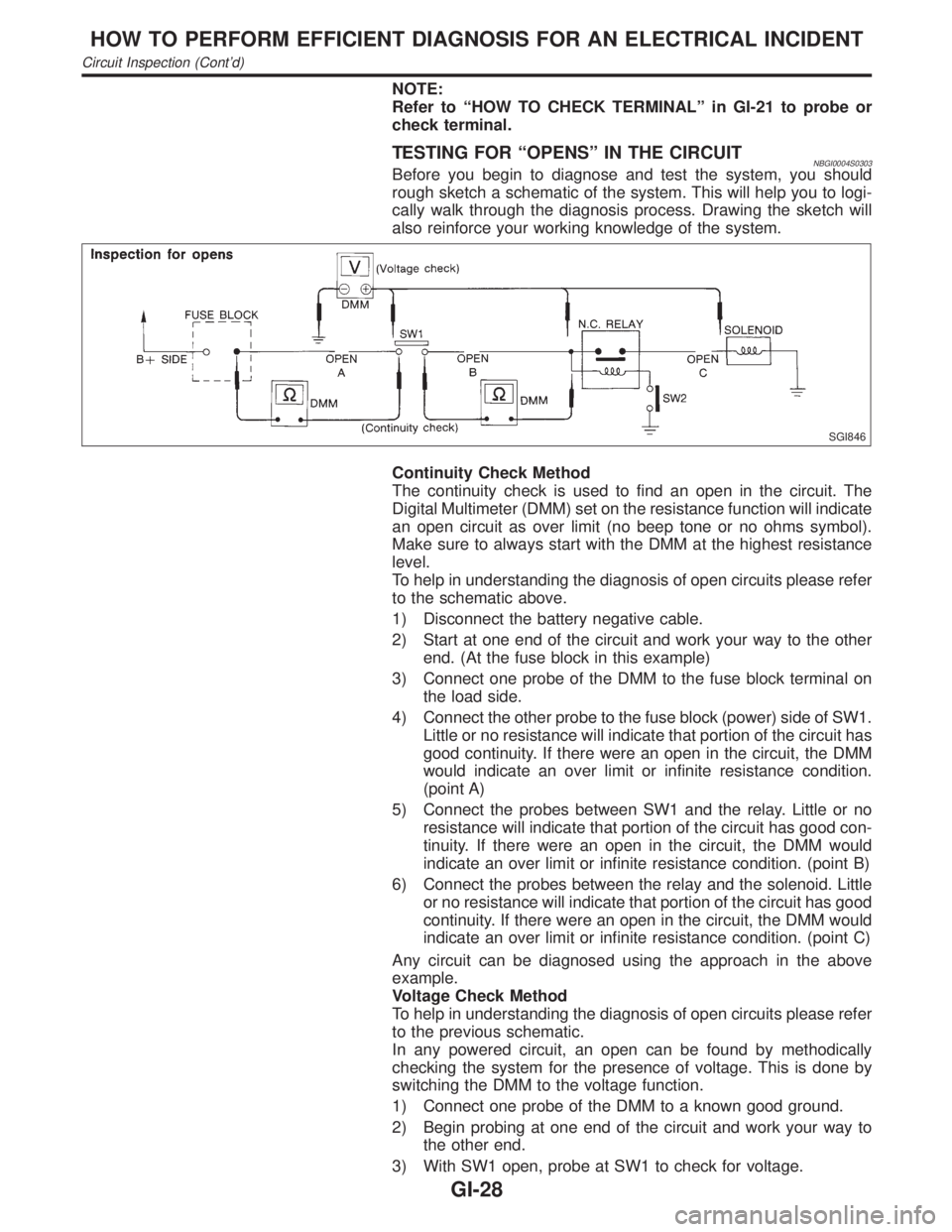
TESTING FOR ªOPENSº IN THE CIRCUITNBGI0004S0303Before you begin to diagnose and test the system, you should
rough sketch a schematic of the system. This will help you to logi-
cally walk through the diagnosis process. Drawing the sketch will
also reinforce your working knowledge of the system.
SGI846
Continuity Check Method
The continuity check is used to find an open in the circuit. The
Digital Multimeter (DMM) set on the resistance function will indicate
an open circuit as over limit (no beep tone or no ohms symbol).
Make sure to always start with the DMM at the highest resistance
level.
To help in understanding the diagnosis of open circuits please refer
to the schematic above.
1) Disconnect the battery negative cable.
2) Start at one end of the circuit and work your way to the other
end. (At the fuse block in this example)
3) Connect one probe of the DMM to the fuse block terminal on
the load side.
4) Connect the other probe to the fuse block (power) side of SW1.
Little or no resistance will indicate that portion of the circuit has
good continuity. If there were an open in the circuit, the DMM
would indicate an over limit or infinite resistance condition.
(point A)
5) Connect the probes between SW1 and the relay. Little or no
resistance will indicate that portion of the circuit has good con-
tinuity. If there were an open in the circuit, the DMM would
indicate an over limit or infinite resistance condition. (point B)
6) Connect the probes between the relay and the solenoid. Little
or no resistance will indicate that portion of the circuit has good
continuity. If there were an open in the circuit, the DMM would
indicate an over limit or infinite resistance condition. (point C)
Any circuit can be diagnosed using the approach in the above
example.
Voltage Check Method
To help in understanding the diagnosis of open circuits please refer
to the previous schematic.
In any powered circuit, an open can be found by methodically
checking the system for the presence of voltage. This is done by
switching the DMM to the voltage function.
1) Connect one probe of the DMM to a known good ground.
2) Begin probing at one end of the circuit and work your way to
the other end.
3) With SW1 open, probe at SW1 to check for voltage.
HOW TO PERFORM EFFICIENT DIAGNOSIS FOR AN ELECTRICAL INCIDENT
Circuit Inspection (Cont'd)
GI-28
Page 1774 of 2395
voltage; open is further down the circuit than SW1.
no voltage; open is between fuse block and SW1 (point A).
4) Close SW1 and probe at relay.
voltage; open is further down the circuit than the relay.
no voltage; open is between SW1 and relay (point B).
5) Close the relay and probe at the solenoid.
voltage; open is further down the circuit than the solenoid.
no voltage; open is between relay and solenoid (point C).
Any powered circuit can be diagnosed using the approach in the
above example.
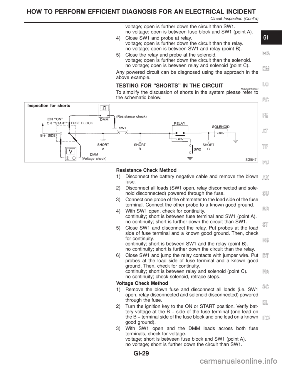
TESTING FOR ªSHORTSº IN THE CIRCUITNBGI0004S0304To simplify the discussion of shorts in the system please refer to
the schematic below.
SGI847
Resistance Check Method
1) Disconnect the battery negative cable and remove the blown
fuse.
2) Disconnect all loads (SW1 open, relay disconnected and sole-
noid disconnected) powered through the fuse.
3) Connect one probe of the ohmmeter to the load side of the fuse
terminal. Connect the other probe to a known good ground.
4) With SW1 open, check for continuity.
continuity; short is between fuse terminal and SW1 (point A).
no continuity; short is further down the circuit than SW1.
5) Close SW1 and disconnect the relay. Put probes at the load
side of fuse terminal and a known good ground. Then, check
for continuity.
continuity; short is between SW1 and the relay (point B).
no continuity; short is further down the circuit than the relay.
6) Close SW1 and jump the relay contacts with jumper wire. Put
probes at the load side of fuse terminal and a known good
ground. Then, check for continuity.
continuity; short is between relay and solenoid (point C).
no continuity; check solenoid, retrace steps.
Voltage Check Method
1) Remove the blown fuse and disconnect all loads (i.e. SW1
open, relay disconnected and solenoid disconnected) powered
through the fuse.
2) Turn the ignition key to the ON or START position. Verify bat-
tery voltage at the B + side of the fuse terminal (one lead on
the B + terminal side of the fuse block and one lead on a known
good ground).
3) With SW1 open and the DMM leads across both fuse
terminals, check for voltage.
voltage; short is between fuse block and SW1 (point A).
no voltage; short is further down the circuit than SW1.
MA
EM
LC
EC
FE
AT
TF
PD
AX
SU
BR
ST
RS
BT
HA
SC
EL
IDX
HOW TO PERFORM EFFICIENT DIAGNOSIS FOR AN ELECTRICAL INCIDENT
Circuit Inspection (Cont'd)
GI-29
Page 1775 of 2395
4) With SW1 closed, relay and solenoid disconnected and the
DMM leads across both fuse terminals, check for voltage.
voltage; short is between SW1 and the relay (point B).
no voltage; short is further down the circuit than the relay.
5) With SW1 closed, relay contacts jumped with fused jumper
wire check for voltage.
voltage; short is down the circuit of the relay or between the
relay and the disconnected solenoid (point C).
no voltage; retrace steps and check power to fuse block.
GROUND INSPECTIONNBGI0004S0305Ground connections are very important to the proper operation of
electrical and electronic circuits. Ground connections are often
exposed to moisture, dirt and other corrosive elements. The corro-
sion (rust) can become an unwanted resistance. This unwanted
resistance can change the way a circuit works.
Electronically controlled circuits are very sensitive to proper
grounding. A loose or corroded ground can drastically affect an
electronically controlled circuit. A poor or corroded ground can eas-
ily affect the circuit. Even when the ground connection looks clean,
there can be a thin film of rust on the surface.
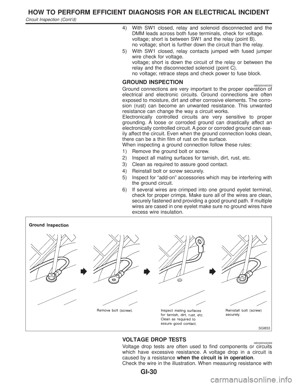
When inspecting a ground connection follow these rules:
1) Remove the ground bolt or screw.
2) Inspect all mating surfaces for tarnish, dirt, rust, etc.
3) Clean as required to assure good contact.
4) Reinstall bolt or screw securely.
5) Inspect for ªadd-onº accessories which may be interfering with
the ground circuit.
6) If several wires are crimped into one ground eyelet terminal,
check for proper crimps. Make sure all of the wires are clean,
securely fastened and providing a good ground path. If multiple
wires are cased in one eyelet make sure no ground wires have
excess wire insulation.
SGI853
VOLTAGE DROP TESTSNBGI0004S0306Voltage drop tests are often used to find components or circuits
which have excessive resistance. A voltage drop in a circuit is
caused by a resistancewhen the circuit is in operation.
Check the wire in the illustration. When measuring resistance with
HOW TO PERFORM EFFICIENT DIAGNOSIS FOR AN ELECTRICAL INCIDENT
Circuit Inspection (Cont'd)
GI-30
Page 1813 of 2395
Refrigeration System
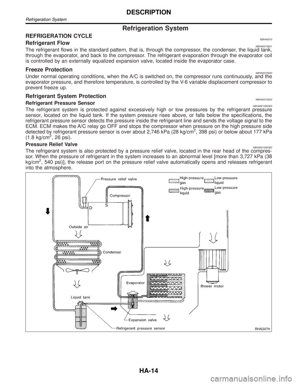
REFRIGERATION CYCLENBHA0010Refrigerant FlowNBHA0010S01The refrigerant flows in the standard pattern, that is, through the compressor, the condenser, the liquid tank,
through the evaporator, and back to the compressor. The refrigerant evaporation through the evaporator coil
is controlled by an externally equalized expansion valve, located inside the evaporator case.
Freeze ProtectionNBHA0010S02Under normal operating conditions, when the A/C is switched on, the compressor runs continuously, and the
evaporator pressure, and therefore temperature, is controlled by the V-6 variable displacement compressor to
prevent freeze up.
Refrigerant System ProtectionNBHA0010S03Refrigerant Pressure SensorNBHA0010S0303The refrigerant system is protected against excessively high or low pressures by the refrigerant pressure
sensor, located on the liquid tank. If the system pressure rises above, or falls below the specifications, the
refrigerant pressure sensor detects the pressure inside the refrigerant line and sends the voltage signal to the
ECM. ECM makes the A/C relay go OFF and stops the compressor when pressure on the high pressure side
detected by refrigerant pressure sensor is over about 2,746 kPa (28 kg/cm
2, 398 psi) or below about 177 kPa
(1.8 kg/cm2, 26 psi).
Pressure Relief Valve
NBHA0010S0302The refrigerant system is also protected by a pressure relief valve, located in the rear head of the compres-
sor. When the pressure of refrigerant in the system increases to an abnormal level [more than 3,727 kPa (38
kg/cm
2, 540 psi)], the release port on the pressure relief valve automatically opens and releases refrigerant
into the atmosphere.
RHA347H
DESCRIPTION
Refrigeration System
HA-14
Page 1905 of 2395

RHA094GB
SYSTEM DESCRIPTION=NBHA0066Auto amplifier controls compressor operation by ambient tempera-
ture and signal from ECM.
Low Temperature Protection ControlNBHA0066S01Auto amplifier will turn the compressor ªONº or ªOFFº as deter-
mined by a signal detected by ambient sensor.
When ambient temperatures are greater than ±2ÉC (28ÉF), the
compressor turns ªONº. The compressor turns ªOFFº when ambi-
ent temperatures are less than þ5ÉC (23ÉF).
RHA877H
DIAGNOSTIC PROCEDURENBHA0067SYMPTOM: Magnet clutch does not engage when AUTO
switch is ON.
1 CHECK POWER SUPPLY FOR COMPRESSOR
Disconnect compressor harness connector. Do approx. 12 volts exist between compressor harness terminal No. 1 and
body ground?
RHA096G
YesorNo
Ye s©Check magnet clutch coil.
1. If NG, replace magnet clutch. Refer to HA-150.
2. Go to self-diagnosis step-by-step procedure (HA-45) and perform self-diagnosis STEP
4.
Confirm that magnet clutch operation is normal.
No©Disconnect A/C relay. And GO TO 2.
TROUBLE DIAGNOSES
Magnet Clutch (Cont'd)
HA-106
Page 1906 of 2395
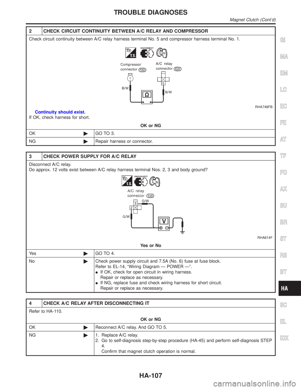
2 CHECK CIRCUIT CONTINUITY BETWEEN A/C RELAY AND COMPRESSOR
Check circuit continuity between A/C relay harness terminal No. 5 and compressor harness terminal No. 1.
RHA748FB
Continuity should exist.
If OK, check harness for short.
OK or NG
OK©GO TO 3.
NG©Repair harness or connector.
3 CHECK POWER SUPPLY FOR A/C RELAY
Disconnect A/C relay.
Do approx. 12 volts exist between A/C relay harness terminal Nos. 2, 3 and body ground?
RHA614F
YesorNo
Ye s©GO TO 4.
No©Check power supply circuit and 7.5A (No. 6) fuse at fuse block.
Refer to EL-14, ªWiring Diagram Ð POWER к.
IIf OK, check for open circuit in wiring harness.
Repair or replace as necessary.
IIf NG, replace fuse and check wiring harness for short circuit.
Repair or replace as necessary.
4 CHECK A/C RELAY AFTER DISCONNECTING IT
Refer to HA-110.
OK or NG
OK©Reconnect A/C relay. And GO TO 5.
NG©1. Replace A/C relay.
2. Go to self-diagnosis step-by-step procedure (HA-45) and perform self-diagnosis STEP
4.
Confirm that magnet clutch operation is normal.
GI
MA
EM
LC
EC
FE
AT
TF
PD
AX
SU
BR
ST
RS
BT
SC
EL
IDX
TROUBLE DIAGNOSES
Magnet Clutch (Cont'd)
HA-107
Page 1907 of 2395

5 CHECK COIL SIDE CIRCUIT OF A/C RELAY
Do approx. 12 volts exist between ECM harness terminal No. 27 and body ground?
RHA482GG
YesorNo
Ye s©GO TO 6.
No©Disconnect A/C relay.
Disconnect ECM harness connector.
GO TO 11.
6 CHECK VOLTAGE FOR ECM
Do approx. 12 volts exist between ECM harness terminal No. 45 and body ground?
RHA701FJ
YesorNo
Ye s©Disconnect ECM harness connector.
Disconnect dual-pressure switch harness connector.
GO TO 7.
No©Check ECM. Refer to EC-127, ªECM Terminals and Reference Valueº.
TROUBLE DIAGNOSES
Magnet Clutch (Cont'd)
HA-108
Page 1909 of 2395
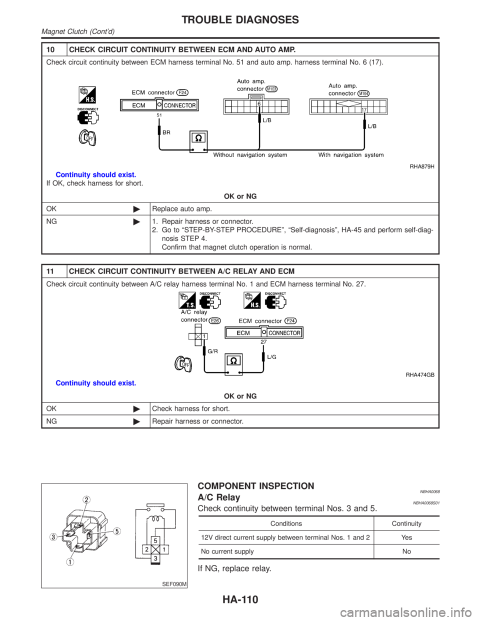
10 CHECK CIRCUIT CONTINUITY BETWEEN ECM AND AUTO AMP.
Check circuit continuity between ECM harness terminal No. 51 and auto amp. harness terminal No. 6 (17).
RHA879H
Continuity should exist.
If OK, check harness for short.
OK or NG
OK©Replace auto amp.
NG©1. Repair harness or connector.
2. Go to ªSTEP-BY-STEP PROCEDUREº, ªSelf-diagnosisº, HA-45 and perform self-diag-
nosis STEP 4.
Confirm that magnet clutch operation is normal.
11 CHECK CIRCUIT CONTINUITY BETWEEN A/C RELAY AND ECM
Check circuit continuity between A/C relay harness terminal No. 1 and ECM harness terminal No. 27.
RHA474GB
Continuity should exist.
OK or NG
OK©Check harness for short.
NG©Repair harness or connector.
SEF090M
COMPONENT INSPECTIONNBHA0068A/C RelayNBHA0068S01Check continuity between terminal Nos. 3 and 5.
Conditions Continuity
12V direct current supply between terminal Nos. 1 and 2 Yes
No current supply No
If NG, replace relay.
TROUBLE DIAGNOSES
Magnet Clutch (Cont'd)
HA-110