2001 INFINITI QX4 key
[x] Cancel search: keyPage 2129 of 2395
![INFINITI QX4 2001 Factory Service Manual SRS701
If no malfunction is detected on ªSELF-DIAG [CURRENT]º even
though malfunction is detected in ªSRS Operation Checkº, check
the battery voltage.
If the battery voltage is less than 9V, charg INFINITI QX4 2001 Factory Service Manual SRS701
If no malfunction is detected on ªSELF-DIAG [CURRENT]º even
though malfunction is detected in ªSRS Operation Checkº, check
the battery voltage.
If the battery voltage is less than 9V, charg](/manual-img/42/57027/w960_57027-2128.png)
SRS701
If no malfunction is detected on ªSELF-DIAG [CURRENT]º even
though malfunction is detected in ªSRS Operation Checkº, check
the battery voltage.
If the battery voltage is less than 9V, charge the battery. Then go
to DIAGNOSTIC PROCEDURE 3, page RS-42.
If the battery voltage is OK, go to DIAGNOSTIC PROCEDURE 4,
page RS-44, to diagnose the following cases:
ISelf-diagnostic result ªSELF-DIAG [PAST]º (previously stored
in the memory) might not be erased after repair.
IThe SRS system malfunctions intermittently.
8. Touch ªPRINTº.
9. Compare diagnostic codes to ªCONSULT-II Diagnostic Code
Chartº, page RS-40.
10. Touch ªBACKº key of CONSULT-II until ªSELECT SYSTEMº
appears in order to return to User mode from Diagnosis mode.
11. Turn ignition switch ªOFFº, then turn off and disconnect
CONSULT-II, and disconnect both battery cables.
12. Repair the system as outlined by the ªRepair orderº in ªCON-
SULT-II Diagnostic Code Chartº, that corresponds to the self-
diagnostic result. For replacement procedure of component
parts, refer to RS-15.
13. After repairing the system, go to DIAGNOSTIC PROCEDURE
3, page RS-42 for final checking.
CONSULT-II Diagnostic Code Chart (ªSELF-DIAG
[CURRENT]º)
NBRS0045S0101
Diagnostic item ExplanationRepair order
ªRecheck SRS at each replace-
ment.º
NO DTC IS
DETECTED.When malfunction is
indicated by the ªAIR
BAGº warning lamp in
User modeILow battery voltage (Less than 9V)IGo to DIAGNOSTIC PROCEDURE 3
(RS-42) after charging battery.
ISelf-diagnostic result ªSELF-DIAG
[PAST]º (previously stored in the
memory) might not be erased after
repair.
IIntermittent malfunction has been
detected in the past.IGo to DIAGNOSTIC PROCEDURE 4
(RS-44).
INo malfunction is detected.IGo to DIAGNOSTIC PROCEDURE 3
(RS-42).
AIRBAG MODULE
[OPEN]IDriver's air bag module circuit is open. (including the spiral
cable)1. Visually check the wiring harness
connection.
2. Replace the harness if it has visible
damage.
3. Replace driver's air bag module.
(Before disposal of it, it must be
deployed.)
4. Replace the spiral cable.
5. Replace the diagnosis sensor unit.
6. Replace the related harness.
SUPPLEMENTAL RESTRAINT SYSTEM (SRS)
Trouble Diagnoses with CONSULT-II (Cont'd)
RS-40
Page 2132 of 2395
![INFINITI QX4 2001 Factory Service Manual SRS771
5. Touch ªAIR BAGº.
SRS697
6. Touch ªSELF-DIAG [CURRENT]º.
SRS701
7. If no malfunction is detected on ªSELF-DIAG [CURRENT]º,
repair of SRS is completed. Go to step 8.
If any malfunction i INFINITI QX4 2001 Factory Service Manual SRS771
5. Touch ªAIR BAGº.
SRS697
6. Touch ªSELF-DIAG [CURRENT]º.
SRS701
7. If no malfunction is detected on ªSELF-DIAG [CURRENT]º,
repair of SRS is completed. Go to step 8.
If any malfunction i](/manual-img/42/57027/w960_57027-2131.png)
SRS771
5. Touch ªAIR BAGº.
SRS697
6. Touch ªSELF-DIAG [CURRENT]º.
SRS701
7. If no malfunction is detected on ªSELF-DIAG [CURRENT]º,
repair of SRS is completed. Go to step 8.
If any malfunction is displayed on ªSELF-DIAG [CURRENT]º,
the malfunctioning part is not repaired completely or another
malfunctioning part is detected. Go to DIAGNOSTIC PROCE-
DURE 2, page RS-39, and repair malfunctioning part com-
pletely.
SRS773
8. Touch ªERASEº.
NOTE:
Touch ªERASEº to clear the memory of the malfunction
(ªSELF-DIAG [PAST]º).
If the memory of the malfunction in ªSELF-DIAG [PAST]º is not
erased, the User mode shows the system malfunction by the
operation of the warning lamp even if the malfunction is repaired
completely.
SRS697
9. Touch ªBACKº key of CONSULT-II to ªSELECT SYSTEMº
screen. Touch ªSELF-DIAG [PAST]º.
GI
MA
EM
LC
EC
FE
AT
TF
PD
AX
SU
BR
ST
BT
HA
SC
EL
IDX
SUPPLEMENTAL RESTRAINT SYSTEM (SRS)
Trouble Diagnoses with CONSULT-II (Cont'd)
RS-43
Page 2133 of 2395
![INFINITI QX4 2001 Factory Service Manual SRS702
10. Check that no malfunction is detected on ªSELF-DIAG
[PAST]º.
11. Touch ªBACKº key of CONSULT-II until ªSELECT SYSTEMº
appears in order to return to User mode from Diagnosis mode.
12. INFINITI QX4 2001 Factory Service Manual SRS702
10. Check that no malfunction is detected on ªSELF-DIAG
[PAST]º.
11. Touch ªBACKº key of CONSULT-II until ªSELECT SYSTEMº
appears in order to return to User mode from Diagnosis mode.
12.](/manual-img/42/57027/w960_57027-2132.png)
SRS702
10. Check that no malfunction is detected on ªSELF-DIAG
[PAST]º.
11. Touch ªBACKº key of CONSULT-II until ªSELECT SYSTEMº
appears in order to return to User mode from Diagnosis mode.
12. Turn ignition switch ªOFFº, then turn off and disconnect CON-
SULT-II.
13. Go to ªSRS Operation Checkº, page RS-38 to check SRS
operation by using ªAIR BAGº warning lamp with User mode.
DIAGNOSTIC PROCEDURE 4 (CONTINUED FROM
DIAGNOSTIC PROCEDURE 2)
NBRS0045S03Inspecting SRS malfunctioning record
1 CONSIDER POSSIBILITY OF NOT ERASING SELF-DIAGNOSTIC RESULT AFTER REPAIRING
Is it the first time for maintenance of SRS?
YesorNo
Ye s©Go to DIAGNOSTIC PROCEDURE 5 (RS-44).
No©Self-diagnostic result ªSELF-DIAG [PAST]º (previously stored in the memory) might not
be erased after repair. Go to DIAGNOSTIC PROCEDURE 3, step 8 (RS-42).
SRS844
DIAGNOSTIC PROCEDURE 5NBRS0045S04Inspecting SRS intermittent malfunction by using CONSULT-II
Ð Diagnosis mode
1. Turn ignition switch ªOFFº.
2. Connect CONSULT-II to Data link connector.
SRS695
3. Turn ignition switch ªONº.
4. Touch ªSTARTº.
SUPPLEMENTAL RESTRAINT SYSTEM (SRS)
Trouble Diagnoses with CONSULT-II (Cont'd)
RS-44
Page 2135 of 2395

SRS704
9. Diagnostic code is displayed on ªTROUBLE DIAG RECORDº.
10. Touch ªPRINTº.
11. Compare diagnostic codes to ªIntermittent Malfunction Diag-
nostic Code Chartº, page RS-46.
12. Touch ªBACKº key of CONSULT-II until ªSELECT SYSTEMº
appears.
13. Turn ignition switch ªOFFº, then turn off and disconnect
CONSULT-II, and disconnect both battery cables.
14. Repair the system as outlined by the ªRepair orderº in ªInter-
mittent Malfunction Diagnostic Code Chartº, that corresponds
to the self-diagnostic result. For replacement procedure of
component parts, refer to RS-15.
15. Go to DIAGNOSTIC PROCEDURE 3, page RS-42, for final
checking.
Intermittent Malfunction Diagnostic Code Chart (ªSELF-
DIAG [PAST]º or ªTROUBLE DIAG RECORDº)
NBRS0045S0401
Diagnostic item Explanation Repair order
NO DTC IS
DETECTED.When malfunction is
indicated by the ªAIR
BAGº warning lamp in
User modeILow battery voltage (Less than 9V)IGo to DIAGNOSTIC PROCEDURE
3 (RS-42) after charging battery.
INo malfunction is detected.IGo to DIAGNOSTIC PROCEDURE
3 (RS-42).
AIRBAG MODULE
[OPEN]IDriver's air bag module circuit is open. (including the spiral
cable)1. Visually check the wiring harness
connection.
2. Replace the harness if it has visible
damage.
3. If the harness check result is OK,
replace driver's air bag module
(Before disposal of it, it must be
deployed.), diagnosis sensor unit
and spiral cable. AIRBAG MODULE
[VB-SHORT]IDriver's air bag module circuit is shorted to some power sup-
ply circuit. (including the spiral cable)
AIRBAG MODULE
[GND-SHORT]IDriver's air bag module circuit is shorted to ground. (including
the spiral cable)
AIRBAG MODULE
[SHORT]IDriver's air bag module circuits are shorted to each other.
ASSIST A/B MODULE
[VB-SHORT]IFront passenger air bag module circuit is shorted to some
power supply circuit.1. Visually check the wiring harness
connection.
2. Replace the harness if it has visible
damage.
3. If the harness check result is OK,
replace front air bag module
(Before disposal of it, it must be
deployed.), and diagnosis sensor
unit. ASSIST A/B MODULE
[OPEN]IFront passenger air bag module circuit is open.
ASSIST A/B MODULE
[GND-SHORT]IFront passenger air bag module circuit is shorted to ground.
ASSIST A/B MODULE
[SHORT]IFront passenger air bag module circuits are shorted to each
other.
SUPPLEMENTAL RESTRAINT SYSTEM (SRS)
Trouble Diagnoses with CONSULT-II (Cont'd)
RS-46
Page 2158 of 2395

Trouble Diagnoses with
Battery/Starting/Charging System Tester
NBSC0018CAUTION:
When working with batteries, always wear appropriate eye
protection.
NOTE:
ITo ensure a complete and thorough diagnosis, the battery,
starter and alternator test segments must be done as a set
from start to finish.
IIf battery surface charge is detected while testing, the tester
will prompt you to turn on the headlights to remove the surface
charge.
IIf necessary, the tester will prompt you to determine if the bat-
tery temperature is above or below 0ÉC (32ÉF). Choose the
appropriate selection by pressing the up or down arrow button,
then press ªENTERº to make the selection.
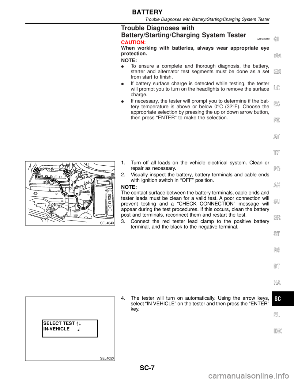
SEL404X
1. Turn off all loads on the vehicle electrical system. Clean or
repair as necessary.
2. Visually inspect the battery, battery terminals and cable ends
with ignition switch in ªOFFº position.
NOTE:
The contact surface between the battery terminals, cable ends and
tester leads must be clean for a valid test. A poor connection will
prevent testing and a ªCHECK CONNECTIONº message will
appear during the test procedures. If this occurs, clean the battery
post and terminals, reconnect them and restart the test.
3. Connect the red tester lead clamp to the positive battery
terminal, and the black to the negative terminal.
SEL405X
4. The tester will turn on automatically. Using the arrow keys,
select ªIN VEHICLEº on the tester and then press the ªENTERº
key.
GI
MA
EM
LC
EC
FE
AT
TF
PD
AX
SU
BR
ST
RS
BT
HA
EL
IDX
BATTERY
Trouble Diagnoses with Battery/Starting/Charging System Tester
SC-7
Page 2159 of 2395

SEL406X
5. Locate the battery type and rating stamped or written on the
top case of the battery to be tested.
NOTE:
The battery type and rating will have either of the following.
CCA: Cold Cranking Amps (490 CCA, 550 CCA, etc.)
JIS: Japanese Industrial Standard.
Battery is stamped with a number such as:
80D26L: 80 (rank of output), D (physical size-depth), 26 (width
in cm). The last character L (post configuration) is not input into
the tester.
The tester requires the rating for the battery be entered exactly
as it is written or stamped on the battery. Do not attempt a CCA
conversion for JIS stamped batteries. JIS must be input
directly.
6. Using the arrow and ªENTERº keys alternately, select the bat-
tery type and rating.
NOTE:
The tester lists five choices; CCA, JIS, IEC, DIN, and EN. Only use
CCA or JIS.
SEL407X
7. Press ªENTERº to begin the test. Diagnosis results are dis-
played on the tester. Refer to ªDIAGNOSTIC RESULT ITEM
CHARTº SC-9.
SEL576X
8. Press ªENTERº, then test output code is displayed. Record the
test output code on the repair order.
9. Toggle back to the ªDIAGNOSTIC SCREENº for test results.
NOTE:
IIf necessary, the tester will ask the user to determine if the
battery has just been charged. Choose the appropriate selec-
tion by pressing the up or down arrow button and then press
the ªENTERº button to make the selection.
IWhen testing a battery installed in a vehicle that has recently
been driven, select ªBEFORE CHANGEº.
IIf the battery has just been slow charged due to a ªCHARGE
& RETESTº decision by the tester, and the tester asks the user
ªBEFORE CHARGE/AFTER CHARGEº, select ªAFTER
CHARGEº.
BATTERY
Trouble Diagnoses with Battery/Starting/Charging System Tester (Cont'd)
SC-8
Page 2189 of 2395

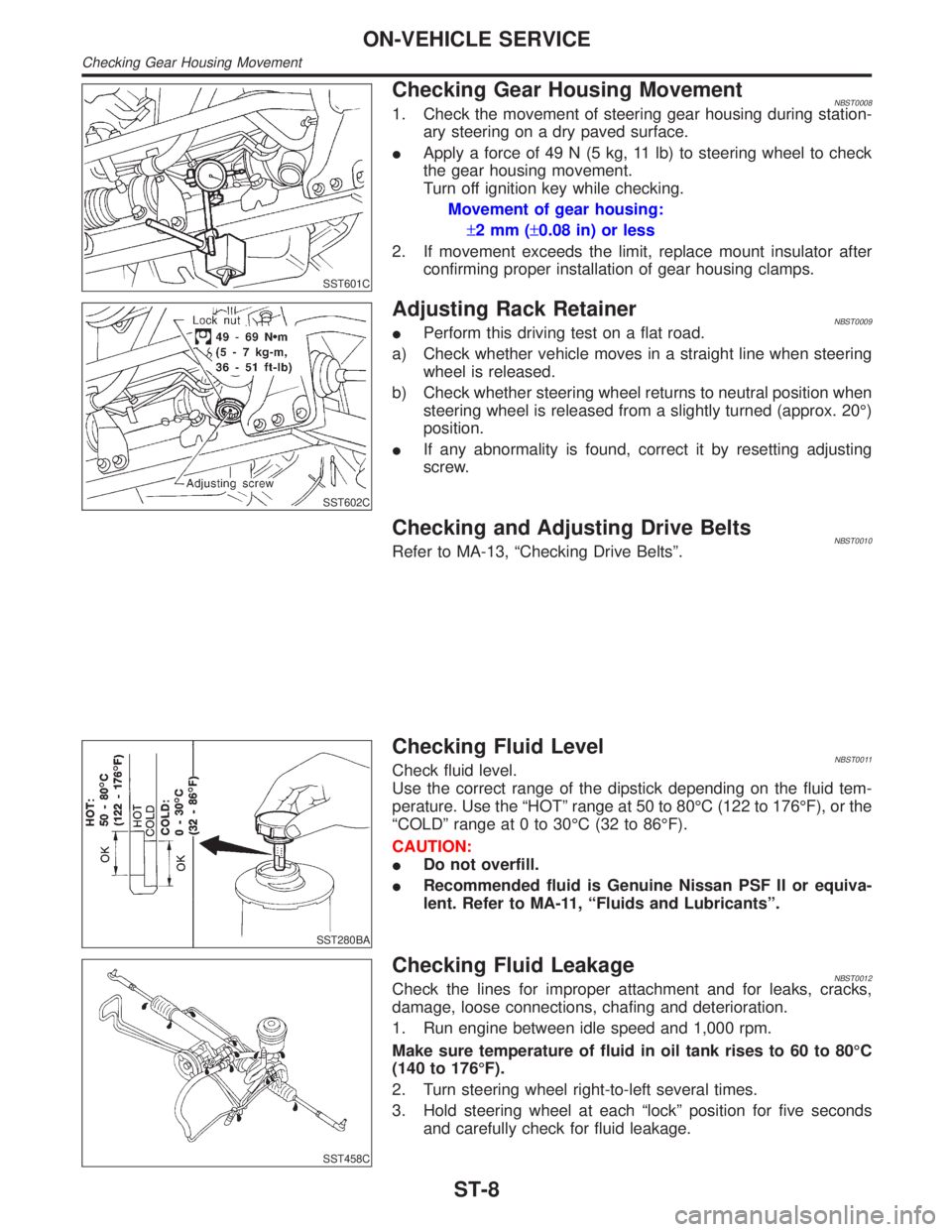
SST601C
Checking Gear Housing MovementNBST00081. Check the movement of steering gear housing during station-
ary steering on a dry paved surface.
IApply a force of 49 N (5 kg, 11 lb) to steering wheel to check
the gear housing movement.
Turn off ignition key while checking.
Movement of gear housing:
±2mm(±0.08 in) or less
2. If movement exceeds the limit, replace mount insulator after
confirming proper installation of gear housing clamps.
SST602C
Adjusting Rack RetainerNBST0009IPerform this driving test on a flat road.
a) Check whether vehicle moves in a straight line when steering
wheel is released.
b) Check whether steering wheel returns to neutral position when
steering wheel is released from a slightly turned (approx. 20É)
position.
IIf any abnormality is found, correct it by resetting adjusting
screw.
Checking and Adjusting Drive BeltsNBST0010Refer to MA-13, ªChecking Drive Beltsº.
SST280BA
Checking Fluid LevelNBST0011Check fluid level.
Use the correct range of the dipstick depending on the fluid tem-
perature. Use the ªHOTº range at 50 to 80ÉC (122 to 176ÉF), or the
ªCOLDº range at 0 to 30ÉC (32 to 86ÉF).
CAUTION:
IDo not overfill.
IRecommended fluid is Genuine Nissan PSF II or equiva-
lent. Refer to MA-11, ªFluids and Lubricantsº.
SST458C
Checking Fluid LeakageNBST0012Check the lines for improper attachment and for leaks, cracks,
damage, loose connections, chafing and deterioration.
1. Run engine between idle speed and 1,000 rpm.
Make sure temperature of fluid in oil tank rises to 60 to 80ÉC
(140 to 176ÉF).
2. Turn steering wheel right-to-left several times.
3. Hold steering wheel at each ªlockº position for five seconds
and carefully check for fluid leakage.
ON-VEHICLE SERVICE
Checking Gear Housing Movement
ST-8
Page 2193 of 2395

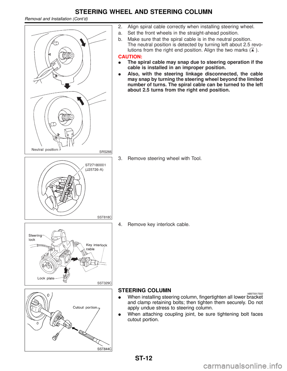
SRS266
2. Align spiral cable correctly when installing steering wheel.
a. Set the front wheels in the straight-ahead position.
b. Make sure that the spiral cable is in the neutral position.
The neutral position is detected by turning left about 2.5 revo-
lutions from the right end position. Align the two marks (
).
CAUTION:
IThe spiral cable may snap due to steering operation if the
cable is installed in an improper position.
IAlso, with the steering linkage disconnected, the cable
may snap by turning the steering wheel beyond the limited
number of turns. The spiral cable can be turned to the left
about 2.5 turns from the right end position.
SST818C
3. Remove steering wheel with Tool.
SST329C
4. Remove key interlock cable.
SST844C
STEERING COLUMNNBST0017S02IWhen installing steering column, fingertighten all lower bracket
and clamp retaining bolts; then tighten them securely. Do not
apply undue stress to steering column.
IWhen attaching coupling joint, be sure tightening bolt faces
cutout portion.
STEERING WHEEL AND STEERING COLUMN
Removal and Installation (Cont'd)
ST-12