Page 954 of 2395
10 km/h (6 MPH) when rotating wheels with suitable gear posi-
tion.
4) If NG, go to ªDiagnostic Procedureº, EC-421.
GI
MA
EM
LC
FE
AT
TF
PD
AX
SU
BR
ST
RS
BT
HA
SC
EL
IDX
DTC P0500 VEHICLE SPEED SENSOR (VSS)
Overall Function Check (Cont'd)
EC-419
Page 963 of 2395
6 CHECK AIR CONTROL VALVE (POWER STEERING) OPERATION-II
Check vacuum hose for vacuum existence when steering wheel is turned.
SEF995Y
Vacuum should exist.
OK or NG
OK©GO TO 9.
NG©GO TO 7.
7 CHECK VACUUM PORT
1. Stop engine.
2. Disconnect vacuum hose connected to air control valve (Power steering) at vacuum port.
3. Blow air into vacuum port.
4. Check that air flows freely.
SEF996Y
OK or NG
OK©GO TO 8.
NG©Repair or clean vacuum port.
DTC P0505 IDLE AIR CONTROL VALVE (IACV) Ð AUXILIARY AIR CONTROL
(AAC) VALVE
Diagnostic Procedure (Cont'd)
EC-428
Page 1052 of 2395

SEF977Y
Component DescriptionNBEC0292The crankshaft position sensor (POS) is located on the oil pan
facing the gear teeth (cogs) of the signal plate (flywheel). It detects
the crankshaft position signal (1É signal).
The sensor consists of a permanent magnet, core and coil.
When engine is running, the gap between the sensor and the gear
teeth (cogs) will periodically change. Permeability near the sensor
also changes.
Due to the permeability change, the magnetic flux near the core is
changed. Therefore, the voltage signal generated in the coil is
changed.
The ECM receives the voltage signal and detects the crankshaft
position signal (1É signal).
CONSULT-II Reference Value in Data Monitor
Mode
NBEC0581Specification data are reference values.
MONITOR ITEM CONDITION SPECIFICATION
CKPS´RPM (POS)ITachometer: Connect
IRun engine and compare tachometer indication with the CONSULT-II
value.Almost the same speed as the
CONSULT-II value.
ENG SPEED
GI
MA
EM
LC
FE
AT
TF
PD
AX
SU
BR
ST
RS
BT
HA
SC
EL
IDX
DTC P1336 CRANKSHAFT POSITION SENSOR (CKPS) (POS) (COG)
Component Description
EC-517
Page 1053 of 2395
ECM Terminals and Reference Value=NBEC0677Specification data are reference values and are measured between each terminal and ground.
CAUTION:
Do not use ECM ground terminals when measuring input/output voltage. Doing so may result in dam-
age to the ECM's transistor. Use a ground other than ECM terminals, such as the ground.
TERMI-
NAL
NO.WIRE
COLORITEM CONDITION DATA (DC Voltage)
85 YCrankshaft position
sensor (POS)[Engine is running]
IIdle speedApproximately 2.4V
SEF057V
[Engine is running]
IEngine speed is 2,000 rpm.Approximately 2.3V
SEF058V
On Board Diagnosis LogicNBEC0294Malfunction is detected when chipping of the signal plate (flywheel
or drive plate) gear tooth (cog) is detected by the ECM.
Possible CauseNBEC0582IHarness or connectors
ICrankshaft position sensor (POS)
ISignal plate (Drive plate/Flywheel)
DTC P1336 CRANKSHAFT POSITION SENSOR (CKPS) (POS) (COG)
ECM Terminals and Reference Value
EC-518
Page 1060 of 2395
13 DETECT MALFUNCTIONING PART
Check the following.
IHarness connectors E132, E135
IHarness connectors E116, M114
IHarness connectors M32, F23
IHarness for open between harness connector E135 and engine ground
©Repair open circuit or short to power in harness or connectors.
14 CHECK GEAR TOOTH
Visually check for chipping signal plate (flywheel or drive plate) gear tooth (cog).
OK or NG
OK©GO TO 15.
NG©Replace the signal plate (flywheel or drive plate).
15 CHECK INTERMITTENT INCIDENT
Refer to ªTROUBLE DIAGNOSIS FOR INTERMITTENT INCIDENTº, EC-140.
©INSPECTION END
GI
MA
EM
LC
FE
AT
TF
PD
AX
SU
BR
ST
RS
BT
HA
SC
EL
IDX
DTC P1336 CRANKSHAFT POSITION SENSOR (CKPS) (POS) (COG)
Diagnostic Procedure (Cont'd)
EC-525
Page 1098 of 2395

SEF355X
Overall Function CheckNBEC0336Use this procedure to check the overall monitoring function of the
EVAP control system purge flow monitoring. During this check, a
1st trip DTC might not be confirmed.
WITH GSTNBEC0336S011) Lift up drive wheels.
2) Start engine (TCS switch ªOFFº) and warm it up to normal
operating temperature.
3) Turn ignition switch ªOFFº, wait at least 10 seconds.
4) Start engine and wait at least 70 seconds.
5) Set voltmeter probes to ECM terminals 84 (EVAP control sys-
tem pressure sensor signal) and ground.
6) Check EVAP control system pressure sensor value at idle
speed and note it.
7) Establish and maintain the following conditions for at least 1
minute.
Air conditioner switch ON
Steering wheel Fully turned
Headlamp switch ON
Rear window defogger switch ON
Engine speed Approx. 3,000 rpm
Gear position Any position other than ªPº, ªNº or ªRº
8) Verify that EVAP control system pressure sensor value stays
0.1V less than the value at idle speed (measured at step 6) for
at least 1 second.
9) If NG, go to ªDiagnostic Procedureº, EC-564.
GI
MA
EM
LC
FE
AT
TF
PD
AX
SU
BR
ST
RS
BT
HA
SC
EL
IDX
DTC P1447 EVAPORATIVE EMISSION (EVAP) CONTROL SYSTEM PURGE
FLOW MONITORING
Overall Function Check
EC-563
Page 1169 of 2395

SEF028Z
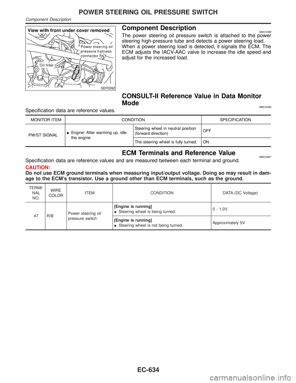
Component DescriptionNBEC0398The power steering oil pressure switch is attached to the power
steering high-pressure tube and detects a power steering load.
When a power steering load is detected, it signals the ECM. The
ECM adjusts the IACV-AAC valve to increase the idle speed and
adjust for the increased load.
CONSULT-II Reference Value in Data Monitor
Mode
NBEC0399Specification data are reference values.
MONITOR ITEM CONDITION SPECIFICATION
PW/ST SIGNALIEngine: After warming up, idle
the engineSteering wheel in neutral position
(forward direction)OFF
The steering wheel is fully turned. ON
ECM Terminals and Reference ValueNBEC0687Specification data are reference values and are measured between each terminal and ground.
CAUTION:
Do not use ECM ground terminals when measuring input/output voltage. Doing so may result in dam-
age to the ECM's transistor. Use a ground other than ECM terminals, such as the ground.
TERMI-
NAL
NO.WIRE
COLORITEM CONDITION DATA (DC Voltage)
47 R/BPower steering oil
pressure switch[Engine is running]
ISteering wheel is being turned.0 - 1.0V
[Engine is running]
ISteering wheel is not being turned.Approximately 5V
POWER STEERING OIL PRESSURE SWITCH
Component Description
EC-634
Page 1184 of 2395

Fuel Pressure RegulatorNBEC0408
Fuel pressure at idling kPa (kg/cm2, psi)
Vacuum hose is connected. Approximately 235 (2.4, 34)
Vacuum hose is disconnected. Approximately 294 (3.0, 43)
Idle Speed and Ignition TimingNBEC0409
Target idle speed*1 No-load*2 (in ªPº or Nº position) 750±50 rpm
Air conditioner: ON In ªPº or Nº position 825 rpm or more
Ignition timing*1 In ªPº or Nº position 15ɱ5É BTDC
Throttle position sensor idle position0.15 - 0.85V
*1: Throttle position sensor harness connector connected
*2: Under the following conditions:
IAir conditioner switch: OFF
IElectric load: OFF (Lights, heater fan & rear window defogger)
ISteering wheel: Kept in straight-ahead position
Mass Air Flow SensorNBEC0411
Supply voltageBattery voltage (11 - 14)V
Output voltage at idle1.2 - 1.8*V
Mass air flow (Using CONSULT-II or GST)2.0 - 6.0 g´m/sec at idle*
7.0 - 20.0 g´m/sec at 2,500 rpm*
*: Engine is warmed up to normal operating temperature and running under no-load.
Engine Coolant Temperature SensorNBEC0412
Temperature ÉC (ÉF) Resistance kW
20 (68) 2.1 - 2.9
50 (122) 0.68 - 1.00
90 (194) 0.236 - 0.260
Heated Oxygen Sensor 1 Heater (Front)NBEC0414
Resistance [at 25ÉC (77ÉF)]2.3 - 4.3W
Fuel PumpNBEC0415
Resistance [at 25ÉC (77ÉF)]0.2 - 5.0W
IACV-AAC ValveNBEC0416
Resistance [at 20ÉC (68ÉF)]Approximately 20 - 24W
InjectorNBEC0417
Resistance [at 20ÉC (68ÉF)]13.5 - 17.5W
ResistorNBEC0418
Resistance [at 25ÉC (77ÉF)]Approximately 2.2 kW
GI
MA
EM
LC
FE
AT
TF
PD
AX
SU
BR
ST
RS
BT
HA
SC
EL
IDX
SERVICE DATA AND SPECIFICATIONS (SDS)
Fuel Pressure Regulator
EC-649