2001 INFINITI QX4 wheel
[x] Cancel search: wheelPage 2238 of 2395
Supplemental Restraint System (SRS) ªAIR
BAGº and ªSEAT BELT PRE-TENSIONERº
NBTF0001The Supplemental Restraint System such as ªAIR BAGº and ªSEAT BELT PRE-TENSIONERº used along with
a seat belt, helps to reduce the risk or severity of injury to the driver and front passenger for certain types of
collision. The SRS system composition which is available to INFINITI QX4 is as follows:
IFor a frontal collision
The Supplemental Restraint System consists of driver air bag module (located in the center of the steer-
ing wheel), front passenger air bag module (located on the instrument panel on passenger side), seat belt
pre-tensioners, a diagnosis sensor unit, warning lamp, wiring harness and spiral cable.
IFor a side collision
The Supplemental Restraint System consists of side air bag module (located in the outer side of front seat),
satellite sensor, diagnosis sensor unit (one of components of air bags for a frontal collision), wiring harness,
warning lamp (one of components of air bags for a frontal collision).
Information necessary to service the system safely is included in theRSsection of this Service Manual.
WARNING:
ITo avoid rendering the SRS inoperative, which could increase the risk of personal injury or death
in the event of a collision which would result in air bag inflation, all maintenance must be performed
by an authorized INFINITI dealer.
IImproper maintenance, including incorrect removal and installation of the SRS, can lead to per-
sonal injury caused by unintentional activation of the system. For removal of Spiral Cable and Air
Bag Module, see the RS section.
IDo not use electrical test equipment on any circuit related to the SRS unless instructed to in this
Service Manual. Spiral cable and wiring harnesses covered with yellow insulation tape either just
before the harness connectors or for the complete harness are related to the SRS.
SEF289H
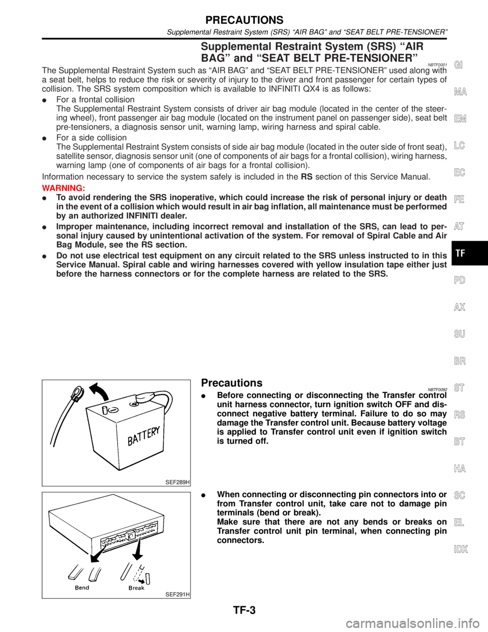
PrecautionsNBTF0092IBefore connecting or disconnecting the Transfer control
unit harness connector, turn ignition switch OFF and dis-
connect negative battery terminal. Failure to do so may
damage the Transfer control unit. Because battery voltage
is applied to Transfer control unit even if ignition switch
is turned off.
SEF291H
IWhen connecting or disconnecting pin connectors into or
from Transfer control unit, take care not to damage pin
terminals (bend or break).
Make sure that there are not any bends or breaks on
Transfer control unit pin terminal, when connecting pin
connectors.
GI
MA
EM
LC
EC
FE
AT
PD
AX
SU
BR
ST
RS
BT
HA
SC
EL
IDX
PRECAUTIONS
Supplemental Restraint System (SRS) ªAIR BAGº and ªSEAT BELT PRE-TENSIONERº
TF-3
Page 2251 of 2395
2-4WD SHIFT SOLENOID VALVENBTF0067S03The 2-4WD shift solenoid valve operates to apply oil pressure to the wet, multiplate clutch, depending on the
drive mode. The driving force is transmitted to the front wheels through the clutch so the vehicle is set in the
4WD mode. Setting the vehicle in the 2WD mode requires no pressure buildup. In other words, pressure force
applied to the wet, multiplate clutch becomes zero.
LINE PRESSURE SWITCHNBTF0067S041. With the transfer system design, control of the oil pressure provides the transmission of drive torque to
the front wheels. The main pressure to control the oil pressure is referred to as the line pressure.
The line pressure switch determines whether or not adequate line pressure has built up under different
operating conditions.
2. The line pressure switch turns ON when line pressure is produced.
3. The line pressure switch senses line pressure abnormalities and turns the 4WD warning lamp ON.
ALL-MODE 4WD SYSTEM
Description of Electrical Parts (Cont'd)
TF-16
Page 2273 of 2395
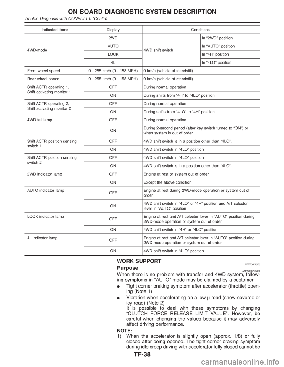
Indicated items Display Conditions
4WD-mode2WD
4WD shift switchIn ª2WDº position
AUTO In ªAUTOº position
LOCK In ª4Hº position
4L In ª4LOº position
Front wheel speed 0 - 255 km/h (0 - 158 MPH) 0 km/h (vehicle at standstill)
Rear wheel speed 0 - 255 km/h (0 - 158 MPH) 0 km/h (vehicle at standstill)
Shift ACTR operating 1,
Shift activating monitor 1OFF During normal operation
ON During shifts from ª4Hº to ª4LOº position
Shift ACTR operating 2,
Shift activating monitor 2OFF During normal operation
ON During shifts from ª4LOº to ª4Hº position
4WD fail lamp OFF During normal operation
ONDuring 2-second period (after key switch turned to ªONº) or
when system is out of order
Shift ACTR position sensing
switch 1OFF 4WD shift switch is in a position other than ª4LOº.
ON 4WD shift switch in ª4LOº position
Shift ACTR position sensing
switch 2OFF 4WD shift switch in ª4LOº position
ON 4WD shift switch is in a position other than ª4LOº.
2WD indicator lamp OFF Engine at rest or system out of order
ON Except the above condition
AUTO indicator lamp
OFFEngine at rest during 2WD-mode operation or system out of
order
ON4WD shift switch in ª4LOº or ª4Hº position and A/T selector
lever in ªAUTOº position
LOCK indicator lamp
OFFEngine at rest and A/T selector lever in ªAUTOº position during
2WD-mode operation or system out of order
ON 4WD shift switch in ª4Hº or ª4LOº position
4L indicator lamp
OFFEngine at rest and A/T selector lever in ªAUTOº position during
2WD-mode operation or system out of order
ON 4WD shift switch in ª4LOº position
WORK SUPPORTNBTF0012S06PurposeNBTF0012S0601When there is no problem with transfer and 4WD system, follow-
ing symptoms in ªAUTOº mode may be claimed by a customer.
ITight corner braking symptom after accelerator (throttle) open-
ing (Note 1)
IVibration when accelerating on a low road (snow-covered or
icy road) (Note 2)
It is possible to deal with these symptoms by changing
ªCLUTCH FORCE RELEASE LIMIT VALUEº. However, be
careful when changing the values because it may adversely
affect driving performance.
NOTE:
1) When the accelerator is slightly open (approx. 1/8) or fully
closed after being opened. The tight corner braking symptom
during idle creep driving with accelerator fully closed cannot be
ON BOARD DIAGNOSTIC SYSTEM DESCRIPTION
Trouble Diagnosis with CONSULT-II (Cont'd)
TF-38
Page 2287 of 2395
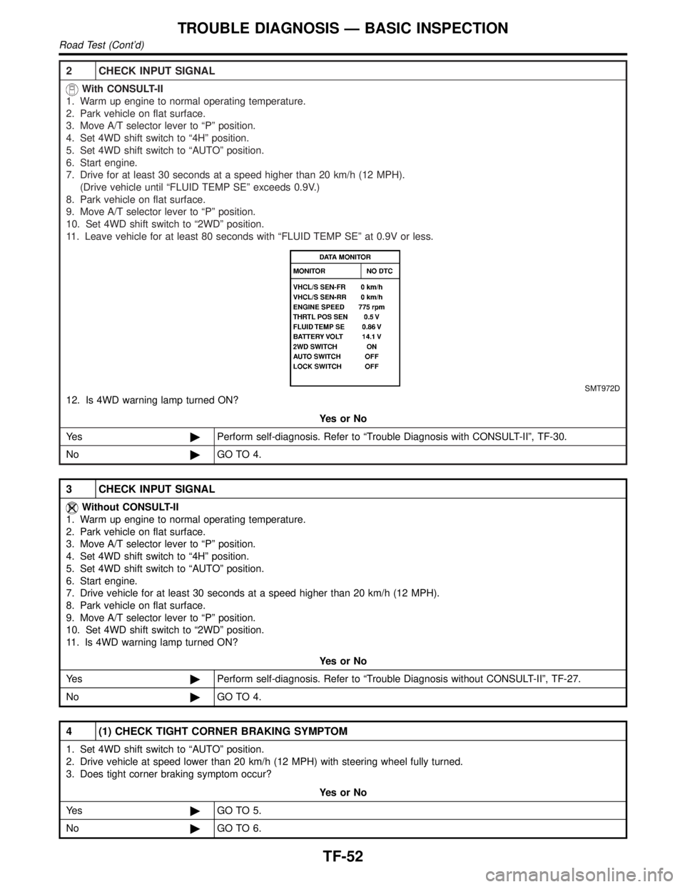
2 CHECK INPUT SIGNAL
With CONSULT-II
1. Warm up engine to normal operating temperature.
2. Park vehicle on flat surface.
3. Move A/T selector lever to ªPº position.
4. Set 4WD shift switch to ª4Hº position.
5. Set 4WD shift switch to ªAUTOº position.
6. Start engine.
7. Drive for at least 30 seconds at a speed higher than 20 km/h (12 MPH).
(Drive vehicle until ªFLUID TEMP SEº exceeds 0.9V.)
8. Park vehicle on flat surface.
9. Move A/T selector lever to ªPº position.
10. Set 4WD shift switch to ª2WDº position.
11. Leave vehicle for at least 80 seconds with ªFLUID TEMP SEº at 0.9V or less.
SMT972D
12. Is 4WD warning lamp turned ON?
YesorNo
Ye s©Perform self-diagnosis. Refer to ªTrouble Diagnosis with CONSULT-IIº, TF-30.
No©GO TO 4.
3 CHECK INPUT SIGNAL
Without CONSULT-II
1. Warm up engine to normal operating temperature.
2. Park vehicle on flat surface.
3. Move A/T selector lever to ªPº position.
4. Set 4WD shift switch to ª4Hº position.
5. Set 4WD shift switch to ªAUTOº position.
6. Start engine.
7. Drive vehicle for at least 30 seconds at a speed higher than 20 km/h (12 MPH).
8. Park vehicle on flat surface.
9. Move A/T selector lever to ªPº position.
10. Set 4WD shift switch to ª2WDº position.
11. Is 4WD warning lamp turned ON?
YesorNo
Ye s©Perform self-diagnosis. Refer to ªTrouble Diagnosis without CONSULT-IIº, TF-27.
No©GO TO 4.
4 (1) CHECK TIGHT CORNER BRAKING SYMPTOM
1. Set 4WD shift switch to ªAUTOº position.
2. Drive vehicle at speed lower than 20 km/h (12 MPH) with steering wheel fully turned.
3. Does tight corner braking symptom occur?
YesorNo
Ye s©GO TO 5.
No©GO TO 6.
TROUBLE DIAGNOSIS Ð BASIC INSPECTION
Road Test (Cont'd)
TF-52
Page 2288 of 2395
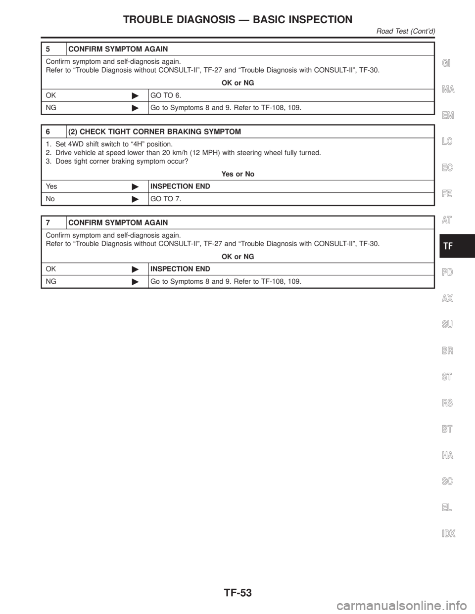
5 CONFIRM SYMPTOM AGAIN
Confirm symptom and self-diagnosis again.
Refer to ªTrouble Diagnosis without CONSULT-IIº, TF-27 and ªTrouble Diagnosis with CONSULT-IIº, TF-30.
OK or NG
OK©GO TO 6.
NG©Go to Symptoms 8 and 9. Refer to TF-108, 109.
6 (2) CHECK TIGHT CORNER BRAKING SYMPTOM
1. Set 4WD shift switch to ª4Hº position.
2. Drive vehicle at speed lower than 20 km/h (12 MPH) with steering wheel fully turned.
3. Does tight corner braking symptom occur?
YesorNo
Ye s©INSPECTION END
No©GO TO 7.
7 CONFIRM SYMPTOM AGAIN
Confirm symptom and self-diagnosis again.
Refer to ªTrouble Diagnosis without CONSULT-IIº, TF-27 and ªTrouble Diagnosis with CONSULT-IIº, TF-30.
OK or NG
OK©INSPECTION END
NG©Go to Symptoms 8 and 9. Refer to TF-108, 109.
GI
MA
EM
LC
EC
FE
AT
PD
AX
SU
BR
ST
RS
BT
HA
SC
EL
IDX
TROUBLE DIAGNOSIS Ð BASIC INSPECTION
Road Test (Cont'd)
TF-53
Page 2342 of 2395
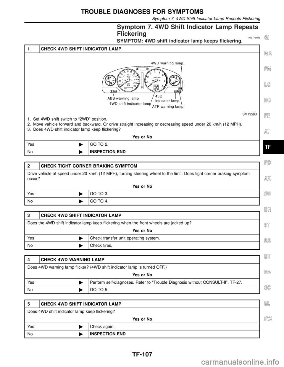
Symptom 7. 4WD Shift Indicator Lamp Repeats
Flickering
=NBTF0035SYMPTOM: 4WD shift indicator lamp keeps flickering.
1 CHECK 4WD SHIFT INDICATOR LAMP
SMT958D
1. Set 4WD shift switch to ª2WDº position.
2. Move vehicle forward and backward. Or drive straight increasing or decreasing speed under 20 km/h (12 MPH).
3. Does 4WD shift indicator lamp keep flickering?
YesorNo
Ye s©GO TO 2.
No©INSPECTION END
2 CHECK TIGHT CORNER BRAKING SYMPTOM
Drive vehicle at speed under 20 km/h (12 MPH), turning steering wheel to the limit. Does tight corner braking symptom
occur?
YesorNo
Ye s©GO TO 3.
No©GO TO 4.
3 CHECK 4WD SHIFT INDICATOR LAMP
Does the 4WD shift indicator lamp keep flickering when the front wheels are jacked up?
YesorNo
Ye s©Check transfer unit operating system.
No©Check tires.
4 CHECK 4WD WARNING LAMP
Does 4WD warning lamp flicker? (4WD shift indicator lamp is turned OFF.)
YesorNo
Ye s©Perform self-diagnoses. Refer to ªTrouble Diagnosis without CONSULT-IIº, TF-27.
No©GO TO 5.
5 CHECK 4WD SHIFT INDICATOR LAMP
Does 4WD shift indicator lamp keep flickering?
YesorNo
Ye s©Check again.
No©INSPECTION END
GI
MA
EM
LC
EC
FE
AT
PD
AX
SU
BR
ST
RS
BT
HA
SC
EL
IDX
TROUBLE DIAGNOSES FOR SYMPTOMS
Symptom 7. 4WD Shift Indicator Lamp Repeats Flickering
TF-107