Page 2221 of 2395

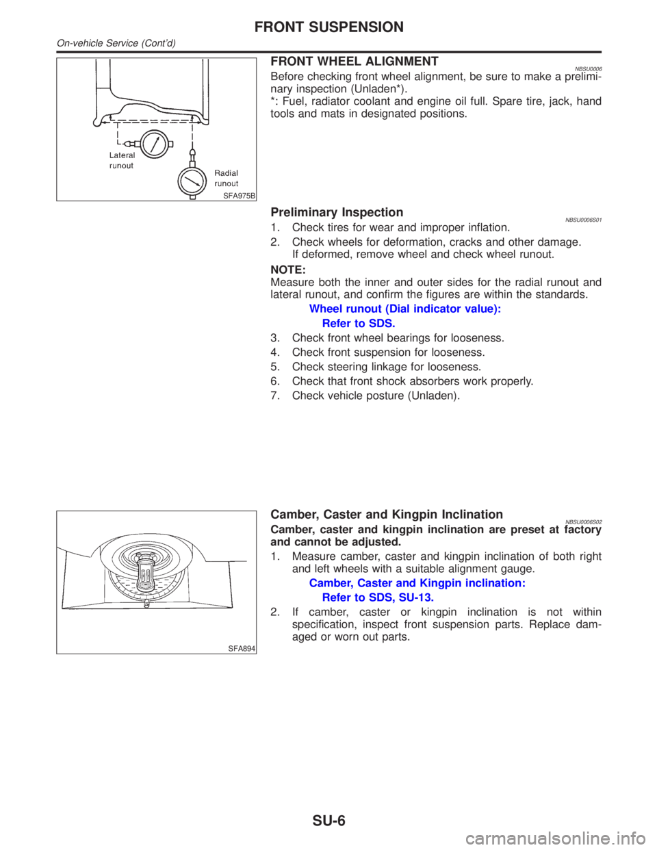
SFA975B
FRONT WHEEL ALIGNMENTNBSU0006Before checking front wheel alignment, be sure to make a prelimi-
nary inspection (Unladen*).
*: Fuel, radiator coolant and engine oil full. Spare tire, jack, hand
tools and mats in designated positions.
Preliminary InspectionNBSU0006S011. Check tires for wear and improper inflation.
2. Check wheels for deformation, cracks and other damage.
If deformed, remove wheel and check wheel runout.
NOTE:
Measure both the inner and outer sides for the radial runout and
lateral runout, and confirm the figures are within the standards.
Wheel runout (Dial indicator value):
Refer to SDS.
3. Check front wheel bearings for looseness.
4. Check front suspension for looseness.
5. Check steering linkage for looseness.
6. Check that front shock absorbers work properly.
7. Check vehicle posture (Unladen).
SFA894
Camber, Caster and Kingpin InclinationNBSU0006S02Camber, caster and kingpin inclination are preset at factory
and cannot be adjusted.
1. Measure camber, caster and kingpin inclination of both right
and left wheels with a suitable alignment gauge.
Camber, Caster and Kingpin inclination:
Refer to SDS, SU-13.
2. If camber, caster or kingpin inclination is not within
specification, inspect front suspension parts. Replace dam-
aged or worn out parts.
FRONT SUSPENSION
On-vehicle Service (Cont'd)
SU-6
Page 2222 of 2395

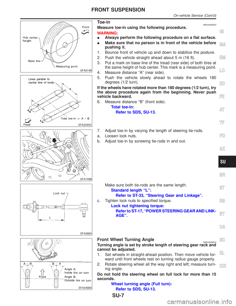
SFA614B
SFA234AC
Toe-inNBSU0006S03Measure toe-in using the following procedure.
WARNING:
IAlways perform the following procedure on a flat surface.
IMake sure that no person is in front of the vehicle before
pushing it.
1. Bounce front of vehicle up and down to stabilize the posture.
2. Push the vehicle straight ahead about 5 m (16 ft).
3. Put a mark on base line of the tread (rear side) of both tires at
the same height of hub center. This mark is a measuring point.
4. Measure distance ªAº (rear side).
5. Push the vehicle slowly ahead to rotate the wheels 180
degrees (1/2 turn).
If the wheels have rotated more than 180 degrees (1/2 turn), try
the above procedure again from the beginning. Never push
vehicle backward.
6. Measure distance ªBº (front side).
Total toe-in:
Refer to SDS, SU-13.
SFA749B
7. Adjust toe-in by varying the length of steering tie-rods.
a. Loosen lock nuts.
b. Adjust toe-in by screwing tie-rods in and out.
SFA486A
Make sure both tie-rods are the same length.
Standard length ªLº:
Refer to ST-33, ªSteering Gear and Linkageº.
c. Tighten lock nuts to specified torque.
Lock nut tightening torque:
Refer to ST-17, ªPOWER STEERING GEAR AND LINK-
AGEº.
SFA439BA
Front Wheel Turning AngleNBSU0006S04Turning angle is set by stroke length of steering gear rack and
cannot be adjusted.
1. Set wheels in straight-ahead position. Then move vehicle for-
ward until front wheels rest on turning radius gauge properly.
2. Rotate steering wheel all the way right and left; measure turn-
ing angle.
Do not hold the steering wheel on full lock for more than 15
seconds.
Wheel turning angle (Full turn):
Refer to SDS, SU-13.
GI
MA
EM
LC
EC
FE
AT
TF
PD
AX
BR
ST
RS
BT
HA
SC
EL
IDX
FRONT SUSPENSION
On-vehicle Service (Cont'd)
SU-7
Page 2226 of 2395
SFA449BA
IInstall stabilizer bar with ball joint socket properly placed.
ARA027
INSPECTIONNBSU0013ICheck stabilizer for deformation and cracks. Replace if neces-
sary.
ICheck rubber bushings for deterioration and cracks. Replace
if necessary.
ICheck ball joint can rotate in all directions. If movement is not
smooth and free, replace stabilizer bar connecting rod.
SFA757B
Transverse Link and Lower Ball Joint
REMOVAL AND INSTALLATIONNBSU00141. Separate drive shaft from knuckle.
Refer to AX-10, ªDrive Shaftº.
2. Separate lower ball joint stud from knuckle.
3. Remove lower ball joint assembly from transverse link.
4. Remove transverse link.
5. During installation, final tightening must be carried out at curb
weight with tires on ground.
6. After installation, check wheel alignment.
Refer to ªFRONT WHEEL ALIGNMENTº, ªOn-vehicle Serviceº,
SU-6.
GI
MA
EM
LC
EC
FE
AT
TF
PD
AX
BR
ST
RS
BT
HA
SC
EL
IDX
FRONT SUSPENSION
Stabilizer Bar (Cont'd)
SU-11
Page 2228 of 2395

Service Data and Specifications (SDS)
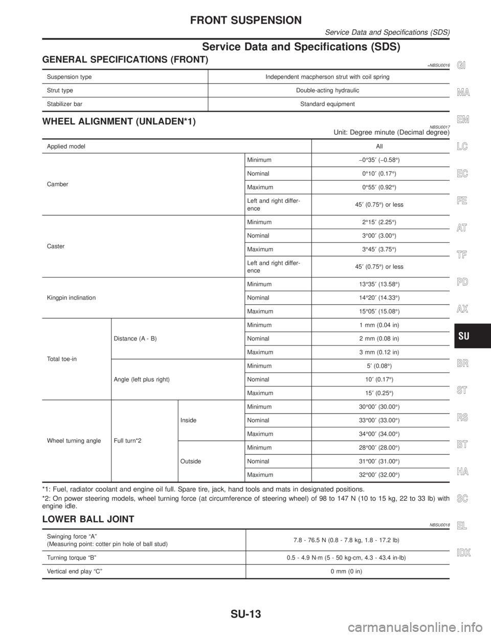
GENERAL SPECIFICATIONS (FRONT)=NBSU0016
Suspension type Independent macpherson strut with coil spring
Strut typeDouble-acting hydraulic
Stabilizer barStandard equipment
WHEEL ALIGNMENT (UNLADEN*1)NBSU0017Unit: Degree minute (Decimal degree)
Applied modelAll
CamberMinimum þ0É35¢(þ0.58É)
Nominal 0É10¢(0.17É)
Maximum 0É55¢(0.92É)
Left and right differ-
ence45¢(0.75É) or less
CasterMinimum 2É15¢(2.25É)
Nominal 3É00¢(3.00É)
Maximum 3É45¢(3.75É)
Left and right differ-
ence45¢(0.75É) or less
Kingpin inclinationMinimum 13É35¢(13.58É)
Nominal 14É20¢(14.33É)
Maximum 15É05¢(15.08É)
Total toe-inDistance (A - B)Minimum 1 mm (0.04 in)
Nominal 2 mm (0.08 in)
Maximum 3 mm (0.12 in)
Angle (left plus right)Minimum 5¢(0.08É)
Nominal 10¢(0.17É)
Maximum 15¢(0.25É)
Wheel turning angle Full turn*2InsideMinimum 30É00¢(30.00É)
Nominal 33É00¢(33.00É)
Maximum 34É00¢(34.00É)
OutsideMinimum 28É00¢(28.00É)
Nominal 31É00¢(31.00É)
Maximum 32É00¢(32.00É)
*1: Fuel, radiator coolant and engine oil full. Spare tire, jack, hand tools and mats in designated positions.
*2: On power steering models, wheel turning force (at circumference of steering wheel) of 98 to 147 N (10 to 15 kg, 22 to 33 lb) with
engine idle.
LOWER BALL JOINTNBSU0018
Swinging force ªAº
(Measuring point: cotter pin hole of ball stud)7.8 - 76.5 N (0.8 - 7.8 kg, 1.8 - 17.2 lb)
Turning torque ªBº 0.5 - 4.9 N´m (5 - 50 kg-cm, 4.3 - 43.4 in-lb)
Vertical end play ªCº0mm(0in)
GI
MA
EM
LC
EC
FE
AT
TF
PD
AX
BR
ST
RS
BT
HA
SC
EL
IDX
FRONT SUSPENSION
Service Data and Specifications (SDS)
SU-13
Page 2229 of 2395
WHEELARCH HEIGHT (UNLADEN*)NBSU0019Unit: mm (in)
SFA746B
Applied model 245/70 R16 tire 245/65 R17 tire
Front (Hf)794 (31.26)
Rear (Hr)810 (31.89)
*: Fuel, radiator coolant and engine oil full. Spare tire, jack, hand tools and mats in designated positions.
WHEEL RUNOUT AVERAGE*NBSU0020Unit: mm (in)
Radial runout limit0.3 (0.012)
Lateral runout limit0.3 (0.012)
*: Wheel runout average = (Outside runout value + Inside runout value) x 0.5
FRONT SUSPENSION
Service Data and Specifications (SDS) (Cont'd)
SU-14
Page 2230 of 2395
SBR686C
Precautions
PRECAUTIONSNBSU0021IWhen installing rubber parts, final tightening must be car-
ried out under unladen condition* with tires on ground.
*Fuel, radiator coolant and engine oil full. Spare tire, jack,
hand tools and mats in designated positions.
IUse flare nut wrench when removing and installing brake
tubes.
IAfter installing removed suspension parts, check wheel
alignment and adjust if necessary.
IAlways torque brake lines when installing.
Preparation
COMMERCIAL SERVICE TOOLSNBSU0023
Tool name Description
1 Flare nut crowfoot
2 Torque wrench
NT360
Removing and installing each brake piping
a: 10 mm (0.39 in)
Noise, Vibration and Harshness (NVH)
Troubleshooting
NBSU0036Refer to ªNoise, Vibration and Harshness (NVH) Troubleshootingº,
ªFRONT SUSPENSIONº, SU-3.
GI
MA
EM
LC
EC
FE
AT
TF
PD
AX
BR
ST
RS
BT
HA
SC
EL
IDX
REAR SUSPENSION
Precautions
SU-15
Page 2231 of 2395
ComponentsNBSU0024
SRA880A
SMA525A
On-vehicle Service
REAR SUSPENSION PARTSNBSU0025Check rear axle and rear suspension parts for excessive play, wear
and damage.
1. Shake each rear wheel to check for excessive play.
2. Retighten all nuts and bolts to the specified torque.
Tightening torque: Refer to ªCoil Spring and Shock
Absorberº, SU-18.
SRA754A
3. Check shock absorber for oil leakage and other damage.
4. Check shock absorber bushing for excessive wear and other
damage.
5. Check wheelarch height. Refer to ªOn-vehicle Serviceº,
ªFRONT SUSPENSIONº, SU-5.
REAR SUSPENSION
Components
SU-16
Page 2232 of 2395
SBR686C
Removal and InstallationNBSU00261. Support axle and suspension components with a suitable jack
and block.
2. Disconnect brake hydraulic line and parking brake cables at
back plates.
CAUTION:
IUse flare nut wrench when removing and installing brake
tubes.
IBefore removing the rear suspension assembly, discon-
nect the ABS wheel sensor from the assembly. Then move
it away from the rear suspension assembly. Failure to do
so may result in damage to the sensor wires and the sen-
sor becoming inoperative.
3. Remove stabilizer bar from body.
4. Remove upper links and lower links from body.
5. Remove panhard rod from body.
6. Disconnect rear end of propeller shaft. Refer to PD-6,
ªRemoval and Installationº.
7. Remove upper end nuts of shock absorber.
SRA935
Final tightening for rubber parts requires to be carried out
under unladen condition with tires on ground.
GI
MA
EM
LC
EC
FE
AT
TF
PD
AX
BR
ST
RS
BT
HA
SC
EL
IDX
REAR SUSPENSION
Removal and Installation
SU-17