Page 319 of 363

If the indicator remains on past three
driving trips, or the f uel cap was not
loose or missing, have the vehicle
checked by the dealer as soon as
possible. Drive moderately until the
dealer has inspected the problem.
Avoid full-throttle acceleration and
driving at high speed.
Youshouldalsohavethedealer
inspect your vehicle if this indicator
comes on repeatedly, even though it
may turn of f as you continue driving.This indicator may also come on
along with the ‘‘D ’’ indicator.
This indicator should light when the
ignition switch is ON (II), and go out
af ter the engine starts. If it comes on
at any other time, it indicates one of
the engine’s emissions control
systems may have a problem. Even
though you may f eel no dif f erence in
your vehicle’s perf ormance, it can
reduce your f uel economy and cause
your vehicle to put out excessive
emissions. Continued operation may
cause serious damage. If you have recently ref ueled your
vehicle, the cause of this indicator
coming on could be a loose or
missing f uel f ill cap. Check the cap
and tighten it until it clicks several
times. Replace the fuel fill cap if it is
missing. Tightening the cap will not
make the indicator turn of f
immediately; it takes at least three
driving trips.
4
T aking Care of t he Unexpect ed
Malf unction Indicator L amp
320
MMAALLFFUUNNCCTTIIOONNIINNDDIICCAATTOORRLLAAMMPP If you keep driving with the
malf unction indicator lamp on, you can
damage your vehicle’s emissions
controls and engine. Those repairs may
not be covered by your vehicle’s
warranties.
Page 321 of 363

�Î�Î
�Î�ÎHowever, if the brake pedal does not
f eel normal, you should take
immediate action. Because of the
brake system’s dual-circuit design, a
problem in one part of the system
will still give you braking at two
wheels. You will f eel the brake pedal
go down much f arther bef ore the
vehicle begins to slow down, and you
will have to press harder on the
pedal. The distance needed to stop
will be much longer.
If it comes on at any other time, it
indicates a problem with the vehicle’s
brake system. In most cases, the
problem is a low f luid level in the
brake f luid reservoir. Press lightly on
the brake pedal to see if it f eels
normal. If it does, check the brake
f luid level the next time you stop at a
service station (see page ). If the
f luid level is low, take the vehicle to
your dealer and have the brake
system inspected f or leaks or worn
brake pads.
Slow down by shif ting to a lower
gear, and pull to the side of the road
when it is saf e. Because of the
longer distance needed to stop, it is
hazardous to drive the vehicle. You
should have it towed, and repaired as
soon as possible. (See
on page .)
If you must drive the vehicle a short
distance in this condition, drive
slowly and cautiously.
If the ABS indicator and the TCS
indicator (on EX model) come on
with this indicator, have the vehicle
inspected by your dealer
immediately.
The Brake System Indicator
normallycomesonwhenyouturn
the ignition switch ON (II). It is a
reminder to check the parking brake.
It comes on and stays lit if you do not
f ully release the parking brake. 260
329
Emergency
Towing
T aking Care of t he Unexpect ed
Brake System Indicator
322
BBRRAAKKEESSYYSSTTEEMMIINNDDIICCAATTOORR
UU..SS..iinnddiiccaattoorrsshhoowwnn
Page 323 of 363
If something electrical in your
vehicle stops working, the first thing
youshouldcheckforisablownfuse.
Determine f rom the chart on pagesand , or the diagram on the
f use box lid (the diagram f or the
driver’s side interior f use box is on
the kick panel below the f use box),
which f use or f uses control that
component. Check those f uses f irst,
but check all the f uses bef ore
deciding that a blown f use is not the
cause. Replace any blown f uses and
check the component’s operation.
Turn the ignition switch to LOCK
(0). Make sure the headlights and
all other accessories are of f .
Remove the cover f rom the f use
box.
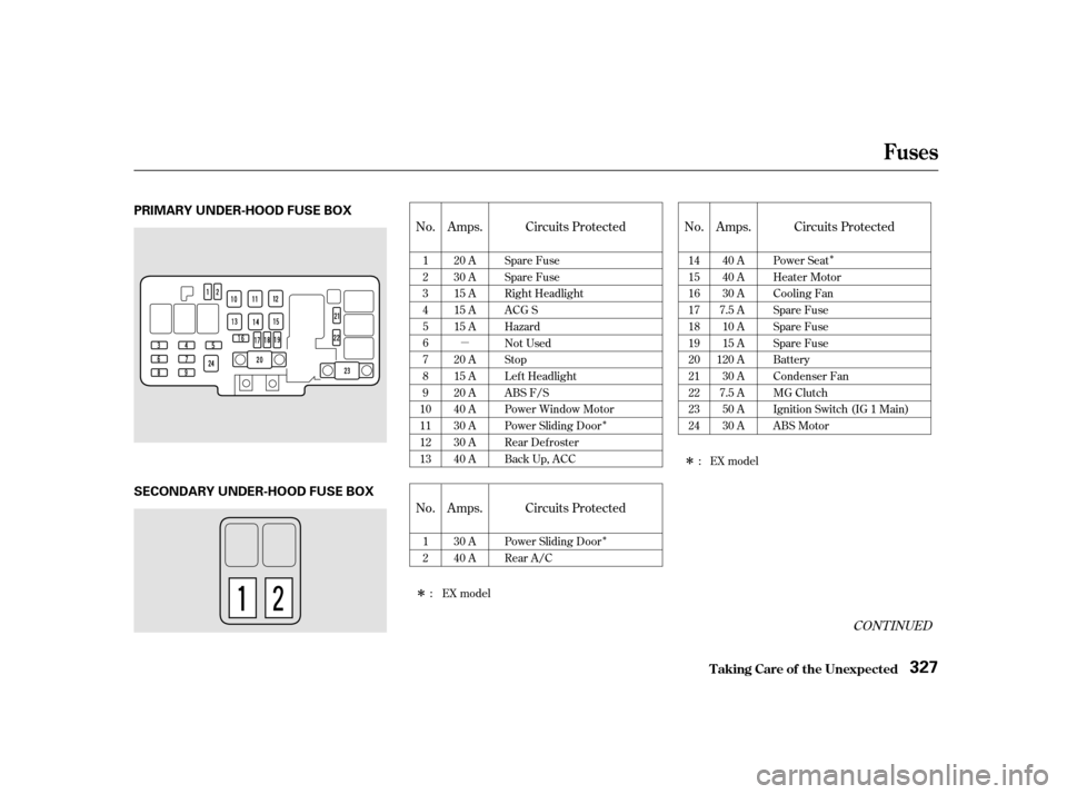
The secondary f use box is in the
engine compartment next to the
battery.
The primary under-hood f use box is
located in the back of the engine
compartment on the passenger’s side.
To open it, push the tabs as shown.
1.
2. 327 328
Fuses
T aking Care of t he Unexpect ed Checking and Replacing Fuses
324
UUNNDDEERR--HHOOOODDUUNNDDEERR--HHOOOODD
Page 326 of 363
�µ�Î
�Î �Î
�Î
�Î
CONT INUED
No. Amps. Circuits Protected No. Amps. Circuits Protected
No. Amps. Circuits Protected 1 23456789
10111213 20 A
30 A
15 A
15 A
15 A
20 A
15 A
20 A
40 A
30 A
30 A
40 A Spare Fuse
Spare Fuse
Right Headlight
ACG S
Hazard
Not Used
Stop
Lef t Headlight
ABS F/S
Power Window Motor
Power Sliding Door
Rear Defroster
Back Up, ACC 1415161718192021222324
40 A
40 A
30 A
7.5 A 10 A
15 A
120 A 30 A
7.5 A 50 A
30 A Power Seat
Heater Motor
Cooling Fan
Spare Fuse
Spare Fuse
Spare Fuse
Battery
Condenser Fan
MG Clutch
Ignition Switch (IG 1 Main)
ABS Motor
12 30 A
40 A Power Sliding Door
Rear A/C :EXmodel
:EXmodel
Fuses
T aking Care of t he Unexpect ed 327
PRIMARY UNDER-HOOD FUSE BOX
SECONDARY UNDER-HOOD FUSE BOX
Page 327 of 363

�Î�Î
�Î �Î
�Î
�Î �Î �Î
On Canadian models
123 4 56789
10111213 15 A
10 A
7.5 A
7.5 A
7.5 A 15 A
10 A
7.5 A 10 A
7.5 A 15 A
30 A
7.5 A Fuel Pump
SRS
Heater Control, A/C Clutch
Relay, Cooling Fan Relay
Power Mirror
Daytime Running Light
ECU(PCM),CruiseControl
Rear Wiper
ACC Relay
Back-up Lights, Instrument
Lights
Turn Signals
IG Coil
Front Wiper
Starter Signal 1 2 345 6 78 9
10 111213141516 20 A
20 A
10 A
20 A
20 A
10 A
7.5 A 20 A
15 A
15 A
15 A
20 A
7.5 A
7.5 A 20 A
7.5 A Driver’s Side Automatic
Sliding Door
Power Seat Reclining
BSC
Power Seat Sliding
Passenger’s Side Automatic
Sliding Door
Daytime Running Light
Left Power Vent
Front Passenger’s Power
Window
ACC Socket
Small Light, License Light
Interior Light, Radio
Power Door Locks
Clock, Back Up
ABS Motor Check
Driver’s Power Window
Right Power Vent
1:2: EX
Canadian models
No. Amps. Circuits Protected No. Amps. Circuits Protected
1
1 1
2
Fuses
T aking Care of t he Unexpect ed
328
Driver’s Side
INTERIOR FUSE BOX
Passenger’s Side
FFrroonnttFFrroonntt
:
Page 334 of 363
")
�µ
�µ �µ �µ �µ �µ �µ�µ�µ�µ�µ�µ�µ �µ �µ
Specif ications
T echnical Inf ormation
335
Lights Battery
Fuses
Engine
Alignment
Tires
12 V 21 W
12 V 21/5 W
3.50 x 3.66 in (89.0 x 93.0 mm)
212 cu-in (3,471 cm
)
9.4 : 1
0.00 in (0.0 mm)
0.00 in (0.0 mm) 0°
0°30’
2°07’
P215/65R16 96T
T135/80D16 101M
35 psi (240 kPa , 2.4 kgf/cm
)
60 psi (420 kPa , 4.2 kgf/cm)
24/2.2 CP
12 V 1.8 W
12 V 8 W
12 V 21 W
12 V 3 CP
2CP
21 CP (18 W)
4CP
10 W
12 V
12 V
12 V
12 V
12 V
60/55 W (HB2)
12 V
65 AH/20 HR
52 AH/5 HR
12 V
12 V
Headlights
Front turn signal/parking/side
marker lights
Rear turn signal lights
Stop/Taillights/Rear side
marker lights
Taillights
Back-up lights
License plate light
High-mount brake light
Individual map lights
Cargo area light
Vanity mirror lights
Capacity
Interior
Under-hood Type
BorexStroke
Displacement
Compression ratio
Spark plugs
Toe-in
CamberCaster Size
Pressure
See page 328 or the fuse label
attached to the dashboard.
See page 328 or the fuse label
attached to the inside of the fuse
box door under the dashboard.
See page 327 or the fuse box
cover. See spark plug maintenance sec-
tion page 266 .
High/Low
Front/Rear
Spare
Front/Rear
Spare
FrontRear
FrontRear
Front
FrontRear
Driver’s side
Passenger’s side
Water cooled 4-stroke SOHC VTEC, 6-cylinder, gasoline engine
Page 339 of 363
, oxides of nitrogen
(NOx) and hydrocarbons (HC).
Gasoline evaporating")
�Î
�Î
The burning of gasoline in your
vehicle’s engine produces several by-
products. Some of these are carbon
monoxide (CO), oxides of nitrogen
(NOx) and hydrocarbons (HC).
Gasoline evaporating f rom the tank
also produces hydrocarbons. Con-
trolling the production of NOx, CO,
and HC is important to the environ-
ment. Under certain conditions of
sunlight and climate, NOx and HC
react to f orm photochemical ‘‘smog.’’
Carbon monoxide does not contri-
bute to smog creation, but it is a
poisonous gas. The United States Clean Air Act
sets standards f or automobile
emissions. It also requires that
automobile manufacturers explain to
owners how their emissions controls
workandwhattodotomaintain
them. This section summarizes how
the emissions controls work.
Scheduled maintenance is on page
.
In Canada, Honda vehicles comply
with the Canadian Motor Vehicle
Saf ety Standards (CMVSS) f or
Emissions valid at the time they are
manuf actured.
Your vehicle has a Positive
Crankcase Ventilation System. This
keeps gasses that build up in the
engine’s crankcase f rom going into
the atmosphere. The Positive Crank-
case Ventilation valve routes them from the crankcase back to the
intake manif old. They are then
drawn into the engine and burned.
As gasoline evaporates in the f uel
tank, an evaporative emissions
control canister f illed with charcoal
adsorbs the vapor. It is stored in this
canister while the engine is of f . Af ter
the engine is started and warmed up,
the vapor is drawn into the engine
and burned during driving.
The Onboard Ref ueling Vapor
Recovery (ORVR) system captures
the f uel vapors during ref ueling. The
vapors are adsorbed in a canister
f illed with activated carbon. While
driving, the f uel vapors are drawn
into the engine and burned of f .
240
The Clean Air Act
Crankcase Emissions Control
System Evaporative Emissions Control
System
Onboard Ref ueling Vapor
Recovery
T echnical Inf ormation
Emissions Cont rols
340
Page 343 of 363
Then drive in city/suburban
traffic for at least 10 minutes.
When traf f ic conditions allow, let
the vehicle coast f or several
seconds without using the
accelerator pedal or the brake
pedal.
If the testing f acility determines the
readiness codes are still not set, see
your Honda dealer.
Select a nearby lightly traveled
major highway where you can
maintain a speed of 50 to 60 mph
(80to90km/h)foratleast20
minutes. Drive on the highway in
D (A/T). Do not use the cruise
control. When traf f ic allows, drive
f or 90 seconds without moving the
accelerator pedal. (Vehicle speed
may vary slightly; this is okay.) If
you cannot do this f or a
continuous 90 seconds because of
traf f ic conditions, drive f or at least
30 seconds, then repeat it two
more times (for a total of 90
seconds). 4
St at e Emissions T est ing
T echnical Inf ormation
344