2001 DODGE TOWN AND COUNTRY back seat installation
[x] Cancel search: back seat installationPage 55 of 2321
INSTALLATION - HUB AND BEARING
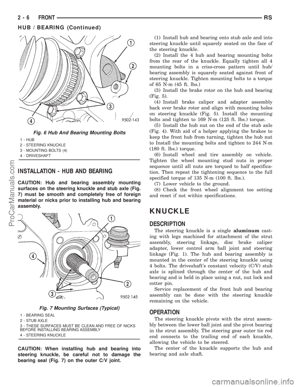
CAUTION: Hub and bearing assembly mounting
surfaces on the steering knuckle and stub axle (Fig.
7) must be smooth and completely free of foreign
material or nicks prior to installing hub and bearing
assembly.
CAUTION: When installing hub and bearing into
steering knuckle, be careful not to damage the
bearing seal (Fig. 7) on the outer C/V joint.(1) Install hub and bearing onto stub axle and into
steering knuckle until squarely seated on the face of
the steering knuckle.
(2) Install the 4 hub and bearing mounting bolts
from the rear of the knuckle. Equally tighten all 4
mounting bolts in a criss-cross pattern until hub/
bearing assembly is squarely seated against front of
steering knuckle. Tighten mounting bolts to a torque
of 65 N´m (45 ft. lbs.)
(3) Install the brake rotor on the hub and bearing
(Fig. 5).
(4) Install brake caliper and adapter assembly
back over brake rotor and align with mounting holes
on steering knuckle (Fig. 5). Install the mounting
bolts and tighten to 169 N´m (125 ft. lbs.) torque.
(5) Install the hub nut on the end of the stub axle
(Fig. 4). With aid of a helper applying the brakes to
keep the front hub from turning, tighten the hub nut
to Install the mounting bolts and tighten to 244 N´m
(180 ft. lbs.) torque.
(6) Install wheel and tire assembly on vehicle.
Tighten the wheel mounting stud nuts in proper
sequence until all nuts are torqued to half specifica-
tion. Then repeat the tightening sequence to the full
specified torque of 135 N´m (100 ft. lbs.).
(7) Lower vehicle to the ground.
(8) Check the front wheel alignment toe setting
and reset if not within specifications.
KNUCKLE
DESCRIPTION
The steering knuckle is a singlealuminumcast-
ing with legs machined for attachment of the strut
assembly, steering linkage, disc brake caliper
adapter, lower control arm ball joint and steering
linkage (Fig. 1). The hub and bearing assembly is
mounted in the center of the steering knuckle using
4 bolts. The driveshaft's constant velocity (C/V) stub
axle is splined through the center of the hub and
bearing and is held in place using a nut, nut lock and
cotter pin.
Service replacement of the front hub and bearing
assembly can be done with the steering knuckle
remaining on the vehicle.
OPERATION
The steering knuckle pivots with the strut assem-
bly between the lower ball joint and the pivot bearing
in the strut assembly. The steering gear outer tie rod
end connects to the trailing end of each knuckle,
allowing the vehicle to be steered.
The center of the knuckle supports the hub and
bearing and axle shaft.
Fig. 6 Hub And Bearing Mounting Bolts
1 - HUB
2 - STEERING KNUCKLE
3 - MOUNTING BOLTS (4)
4 - DRIVESHAFT
Fig. 7 Mounting Surfaces (Typical)
1 - BEARING SEAL
2 - STUB AXLE
3 - THESE SURFACES MUST BE CLEAN AND FREE OF NICKS
BEFORE INSTALLING BEARING ASSEMBLY
4 - STEERING KNUCKLE
2 - 6 FRONTRS
HUB / BEARING (Continued)
ProCarManuals.com
Page 71 of 2321
(1) Position the strut assembly in the strut coil
spring compressor following the manufacturers
instructions. Position the lower hooks on the coil
spring first. The strut clevis bracket should be posi-
tioned straight outward from the compressor.
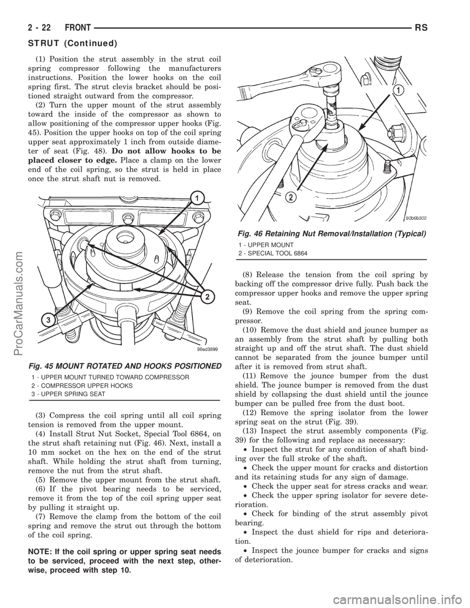
(2) Turn the upper mount of the strut assembly
toward the inside of the compressor as shown to
allow positioning of the compressor upper hooks (Fig.
45). Position the upper hooks on top of the coil spring
upper seat approximately 1 inch from outside diame-
ter of seat (Fig. 48).Do not allow hooks to be
placed closer to edge.Place a clamp on the lower
end of the coil spring, so the strut is held in place
once the strut shaft nut is removed.
(3) Compress the coil spring until all coil spring
tension is removed from the upper mount.
(4) Install Strut Nut Socket, Special Tool 6864, on
the strut shaft retaining nut (Fig. 46). Next, install a
10 mm socket on the hex on the end of the strut
shaft. While holding the strut shaft from turning,
remove the nut from the strut shaft.
(5) Remove the upper mount from the strut shaft.
(6) If the pivot bearing needs to be serviced,
remove it from the top of the coil spring upper seat
by pulling it straight up.
(7) Remove the clamp from the bottom of the coil
spring and remove the strut out through the bottom
of the coil spring.
NOTE: If the coil spring or upper spring seat needs
to be serviced, proceed with the next step, other-
wise, proceed with step 10.(8) Release the tension from the coil spring by
backing off the compressor drive fully. Push back the
compressor upper hooks and remove the upper spring
seat.
(9) Remove the coil spring from the spring com-
pressor.
(10) Remove the dust shield and jounce bumper as
an assembly from the strut shaft by pulling both
straight up and off the strut shaft. The dust shield
cannot be separated from the jounce bumper until
after it is removed from strut shaft.
(11) Remove the jounce bumper from the dust
shield. The jounce bumper is removed from the dust
shield by collapsing the dust shield until the jounce
bumper can be pulled free from the dust boot.
(12) Remove the spring isolator from the lower
spring seat on the strut (Fig. 39).
(13) Inspect the strut assembly components (Fig.
39) for the following and replace as necessary:
²Inspect the strut for any condition of shaft bind-
ing over the full stroke of the shaft.
²Check the upper mount for cracks and distortion
and its retaining studs for any sign of damage.
²Check the upper seat for stress cracks and wear.
²Check the upper spring isolator for severe dete-
rioration.
²Check for binding of the strut assembly pivot
bearing.
²Inspect the dust shield for rips and deteriora-
tion.
²Inspect the jounce bumper for cracks and signs
of deterioration.
Fig. 45 MOUNT ROTATED AND HOOKS POSITIONED
1 - UPPER MOUNT TURNED TOWARD COMPRESSOR
2 - COMPRESSOR UPPER HOOKS
3 - UPPER SPRING SEAT
Fig. 46 Retaining Nut Removal/Installation (Typical)
1 - UPPER MOUNT
2 - SPECIAL TOOL 6864
2 - 22 FRONTRS
STRUT (Continued)
ProCarManuals.com
Page 72 of 2321
ASSEMBLY - STRUT ASSEMBLY
For the disassembly and assembly of the strut
assembly, use of Strut Spring Compressor, Pentastar
Service Equipment (PSE) tool W-7200, or the equiva-
lent, is recommended to compress the coil spring.
Follow the manufacturer's instructions closely.
NOTE: Coil Springs on this vehicle are side-ori-
ented. Springs on the left side of the vehicle have a
left-hand wind top-to-bottom while springs on the
right side have a right-hand wind top-to-bottom.
Left and right springs must not be interchanged.
NOTE: If the coil spring has been removed from the
spring compressor, proceed with the next step, oth-
erwise, proceed with step 5.
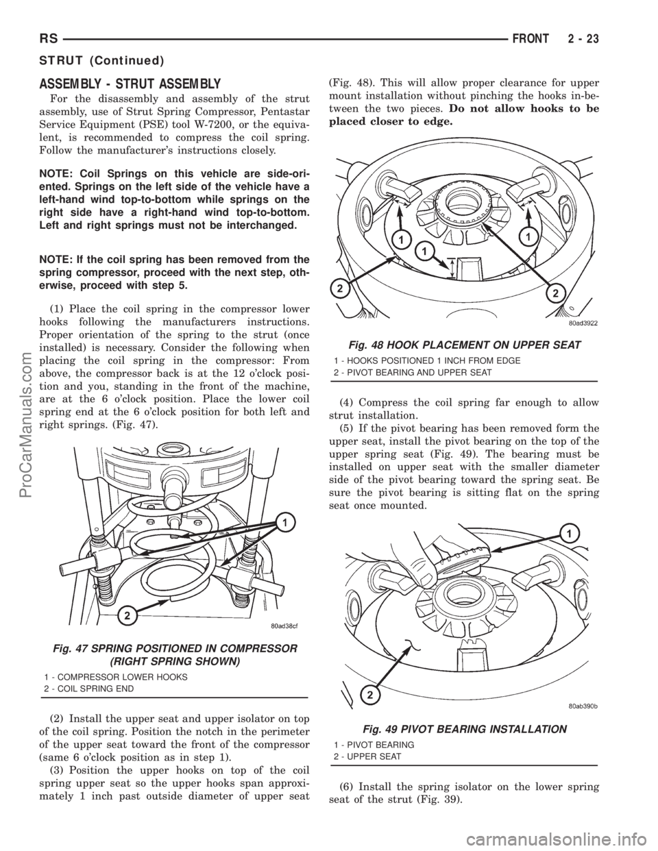
(1) Place the coil spring in the compressor lower
hooks following the manufacturers instructions.
Proper orientation of the spring to the strut (once
installed) is necessary. Consider the following when
placing the coil spring in the compressor: From
above, the compressor back is at the 12 o'clock posi-
tion and you, standing in the front of the machine,
are at the 6 o'clock position. Place the lower coil
spring end at the 6 o'clock position for both left and
right springs. (Fig. 47).
(2) Install the upper seat and upper isolator on top
of the coil spring. Position the notch in the perimeter
of the upper seat toward the front of the compressor
(same 6 o'clock position as in step 1).
(3) Position the upper hooks on top of the coil
spring upper seat so the upper hooks span approxi-
mately 1 inch past outside diameter of upper seat(Fig. 48). This will allow proper clearance for upper
mount installation without pinching the hooks in-be-
tween the two pieces.Do not allow hooks to be
placed closer to edge.
(4) Compress the coil spring far enough to allow
strut installation.
(5) If the pivot bearing has been removed form the
upper seat, install the pivot bearing on the top of the
upper spring seat (Fig. 49). The bearing must be
installed on upper seat with the smaller diameter
side of the pivot bearing toward the spring seat. Be
sure the pivot bearing is sitting flat on the spring
seat once mounted.
(6) Install the spring isolator on the lower spring
seat of the strut (Fig. 39).
Fig. 47 SPRING POSITIONED IN COMPRESSOR
(RIGHT SPRING SHOWN)
1 - COMPRESSOR LOWER HOOKS
2 - COIL SPRING END
Fig. 48 HOOK PLACEMENT ON UPPER SEAT
1 - HOOKS POSITIONED 1 INCH FROM EDGE
2 - PIVOT BEARING AND UPPER SEAT
Fig. 49 PIVOT BEARING INSTALLATION
1 - PIVOT BEARING
2 - UPPER SEAT
RSFRONT2-23
STRUT (Continued)
ProCarManuals.com
Page 73 of 2321
(7) Install the jounce bumper on the strut shaft
(Fig. 39). The jounce bumper is to be installed with
the small end pointing downward.
(8) Install the dust shield on the strut. Collapse
and stretch the dust shield down over the top of the
jounce bumper until the dust shield snaps into the
slot on the jounce bumper. The jounce bumper will be
at the top of the inner dust boot. Return the dust
shield to its fully extended length.
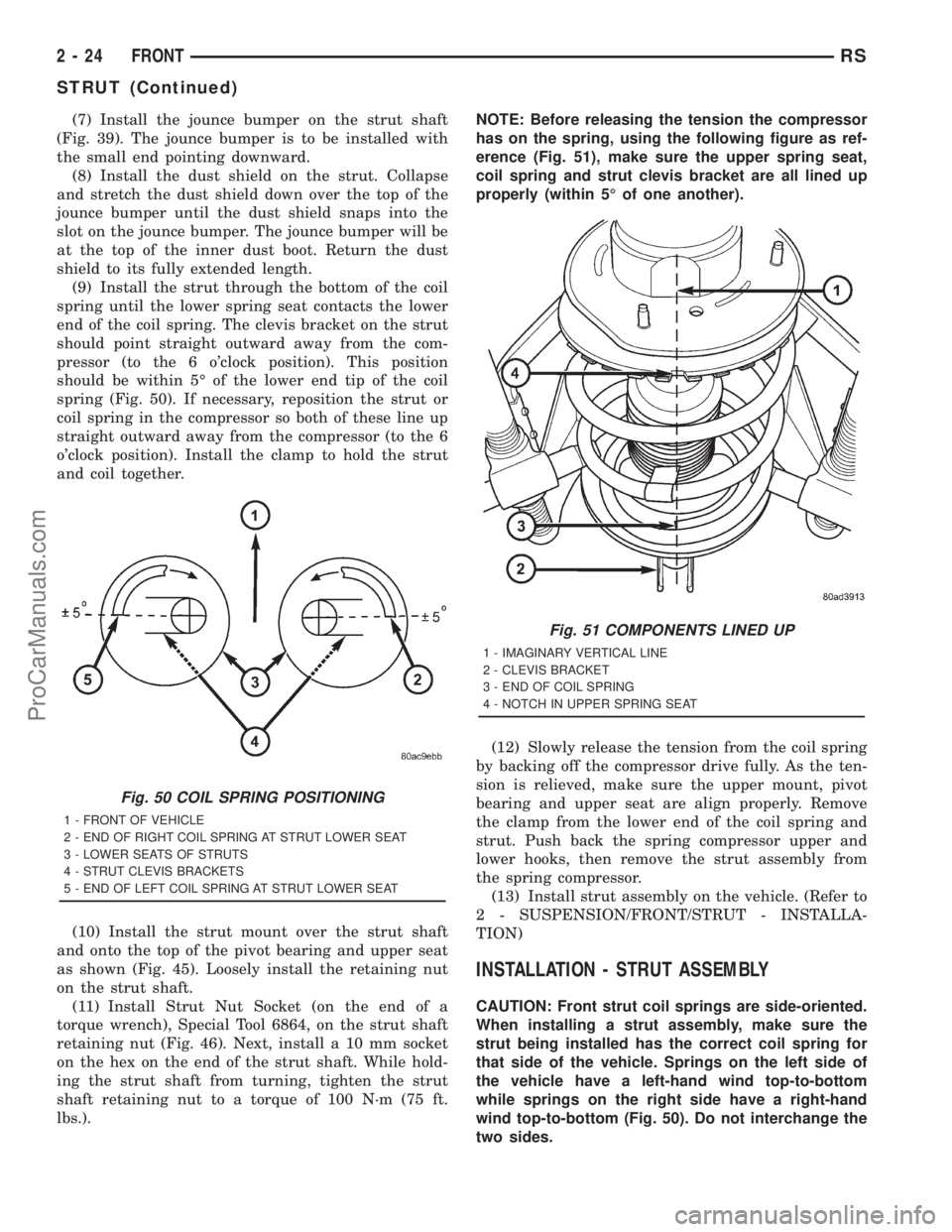
(9) Install the strut through the bottom of the coil
spring until the lower spring seat contacts the lower
end of the coil spring. The clevis bracket on the strut
should point straight outward away from the com-
pressor (to the 6 o'clock position). This position
should be within 5É of the lower end tip of the coil
spring (Fig. 50). If necessary, reposition the strut or
coil spring in the compressor so both of these line up
straight outward away from the compressor (to the 6
o'clock position). Install the clamp to hold the strut
and coil together.
(10) Install the strut mount over the strut shaft
and onto the top of the pivot bearing and upper seat
as shown (Fig. 45). Loosely install the retaining nut
on the strut shaft.
(11) Install Strut Nut Socket (on the end of a
torque wrench), Special Tool 6864, on the strut shaft
retaining nut (Fig. 46). Next, install a 10 mm socket
on the hex on the end of the strut shaft. While hold-
ing the strut shaft from turning, tighten the strut
shaft retaining nut to a torque of 100 N´m (75 ft.
lbs.).NOTE: Before releasing the tension the compressor
has on the spring, using the following figure as ref-
erence (Fig. 51), make sure the upper spring seat,
coil spring and strut clevis bracket are all lined up
properly (within 5É of one another).
(12) Slowly release the tension from the coil spring
by backing off the compressor drive fully. As the ten-
sion is relieved, make sure the upper mount, pivot
bearing and upper seat are align properly. Remove
the clamp from the lower end of the coil spring and
strut. Push back the spring compressor upper and
lower hooks, then remove the strut assembly from
the spring compressor.
(13) Install strut assembly on the vehicle. (Refer to
2 - SUSPENSION/FRONT/STRUT - INSTALLA-
TION)
INSTALLATION - STRUT ASSEMBLY
CAUTION: Front strut coil springs are side-oriented.
When installing a strut assembly, make sure the
strut being installed has the correct coil spring for
that side of the vehicle. Springs on the left side of
the vehicle have a left-hand wind top-to-bottom
while springs on the right side have a right-hand
wind top-to-bottom (Fig. 50). Do not interchange the
two sides.
Fig. 50 COIL SPRING POSITIONING
1 - FRONT OF VEHICLE
2 - END OF RIGHT COIL SPRING AT STRUT LOWER SEAT
3 - LOWER SEATS OF STRUTS
4 - STRUT CLEVIS BRACKETS
5 - END OF LEFT COIL SPRING AT STRUT LOWER SEAT
Fig. 51 COMPONENTS LINED UP
1 - IMAGINARY VERTICAL LINE
2 - CLEVIS BRACKET
3 - END OF COIL SPRING
4 - NOTCH IN UPPER SPRING SEAT
2 - 24 FRONTRS
STRUT (Continued)
ProCarManuals.com
Page 86 of 2321
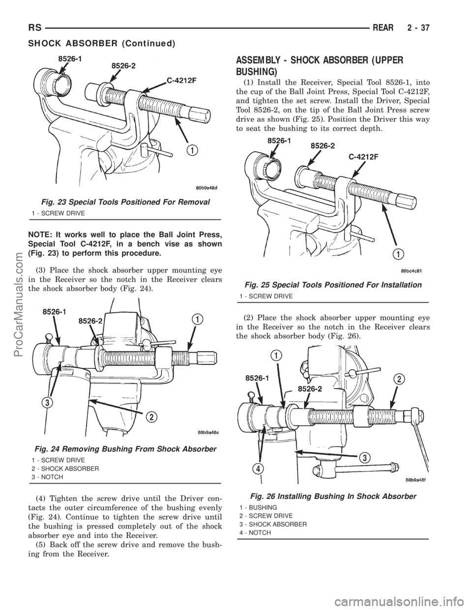
NOTE: It works well to place the Ball Joint Press,
Special Tool C-4212F, in a bench vise as shown
(Fig. 23) to perform this procedure.
(3) Place the shock absorber upper mounting eye
in the Receiver so the notch in the Receiver clears
the shock absorber body (Fig. 24).
(4) Tighten the screw drive until the Driver con-
tacts the outer circumference of the bushing evenly
(Fig. 24). Continue to tighten the screw drive until
the bushing is pressed completely out of the shock
absorber eye and into the Receiver.
(5) Back off the screw drive and remove the bush-
ing from the Receiver.
ASSEMBLY - SHOCK ABSORBER (UPPER
BUSHING)
(1) Install the Receiver, Special Tool 8526-1, into
the cup of the Ball Joint Press, Special Tool C-4212F,
and tighten the set screw. Install the Driver, Special
Tool 8526-2, on the tip of the Ball Joint Press screw
drive as shown (Fig. 25). Position the Driver this way
to seat the bushing to its correct depth.
(2) Place the shock absorber upper mounting eye
in the Receiver so the notch in the Receiver clears
the shock absorber body (Fig. 26).
Fig. 23 Special Tools Positioned For Removal
1 - SCREW DRIVE
Fig. 24 Removing Bushing From Shock Absorber
1 - SCREW DRIVE
2 - SHOCK ABSORBER
3 - NOTCH
Fig. 25 Special Tools Positioned For Installation
1 - SCREW DRIVE
Fig. 26 Installing Bushing In Shock Absorber
1 - BUSHING
2 - SCREW DRIVE
3 - SHOCK ABSORBER
4 - NOTCH
RSREAR2-37
SHOCK ABSORBER (Continued)
ProCarManuals.com
Page 174 of 2321
shoes on the opposite side of the vehicle as well as
the shoes failing inspection.
If the brake shoe assemblies do not require
replacement, be sure to reinstall the brake shoes in
the original position they were remove from.
INSTALLATION - FRONT DISC BRAKE SHOES
(DISC/DISC BRAKES)
(1) Begin on one side of the vehicle or the other.
(2) Completely retract the caliper piston back into
its bore in the brake caliper (This is required for cal-
iper installation on the brake rotor with new brake
shoes installed).
(3) If applied, remove the protective paper from
the noise suppression gasket on the rear of both the
inner and outer brake shoe assemblies.
(4) Install the new inboard brake shoe into the cal-
iper piston by firmly pressing its retaining clip into
the piston bore. Be sure the inboard brake shoe is
positioned squarely against the face of the caliper
piston.
(5) Lubricate both adapter abutments where the
shoes slide with a small amount of MopartMultipur-
pose Lubricant, or equivalent.
(6) Slide the new outboard brake shoe into the cal-
iper adapter up against the outside of the brake
rotor.
CAUTION: Use care when installing the caliper
assembly onto the steering knuckle, so the caliper
guide pin bushings do not get damaged by the
steering knuckle bosses.
(7) Carefully position the brake caliper over the
brake rotor and adapter.
(8) Install the caliper guide pin bolts and tighten
to a torque of 35 N´m (26 ft. lbs.).Extreme caution
should be taken not to cross thread the caliper
guide pin bolts.
(9) Install the anti-rattle clip on the outboard side
of the caliper. Start the clip into the holes on the cal-
iper, then stretch the clip legs past the abutments on
the caliper adapter.
(10) Install the wheel and tire assembly. Tighten
the wheel mounting nuts in proper sequence until all
nuts are torqued to half specification, then repeat the
tightening sequence to the full specified torque of 135
N´m (100 ft. lbs.).
(11) Repeat the above procedure on other side of
the vehicle.
(12) Lower vehicle.
(13) Pump the brake pedal several times. This will
set the shoes to the brake rotor.
(14) Check and adjust brake fluid level as neces-
sary.(15) Road test the vehicle and make several stops
to wear off any foreign material on the brakes and to
seat the brake shoes.
INSTALLATION - FRONT DISC BRAKE SHOES
(DISC/DRUM BRAKES)
NOTE: Perform steps Step 1 through Step 5on each
side of the vehicle.
(1) Place the brake shoes in the adapter anti-rattle
clips.
(2) Completely retract the caliper piston back into
the bore of the caliper.
CAUTION: Use care when installing the caliper onto
the disc brake adapter to avoid damaging the boots
on the caliper guide pins.
(3) Install the disc brake caliper over the brake
shoes on the brake caliper adapter.
(4) Align the caliper guide pin bolt holes with the
guide pins. Install the caliper guide pin bolts and
tighten them to a torque of 35 N´m (26 ft. lbs.) (Fig.
14).
(5) Install the tire and wheel assembly. Tighten
the wheel mounting nuts to a torque of 135 N´m (100
ft. lbs.).
(6) Lower the vehicle.
(7) Pump the brake pedal several times. This will
set the shoes to the brake rotor.
(8) Check and adjust the brake fluid level as nec-
essary.
(9) Road test the vehicle and make several stops to
wear off any foreign material on the brakes and to
seat the brake shoes.
BRAKE PADS/SHOES - REAR
DISC
REMOVAL - REAR DISC BRAKE SHOES
(1) Raise vehicle on jackstands or centered on a
hoist. (Refer to LUBRICATION & MAINTENANCE/
HOISTING - STANDARD PROCEDURE).
(2) Remove rear wheel and tire assemblies from
vehicle.
(3) Remove the caliper to adapter guide pin bolts
(Fig. 15).
(4) Remove rear caliper from adapter using the fol-
lowing procedure. First rotate rear of caliper up from
the adapter. Then pull the front of the caliper and
the outboard brake shoe anti-rattle clip out from
under the front abutment on the adapter (Fig. 16).
RSBRAKES - BASE5-15
BRAKE PADS/SHOES - FRONT (Continued)
ProCarManuals.com
Page 176 of 2321
CLEANING - DISC BRAKE SHOES
WARNING: DUST AND DIRT ACCUMULATING ON
BRAKE PARTS DURING NORMAL USE MAY CON-
TAIN ASBESTOS FIBERS FROM PRODUCTION OR
AFTERMARKET BRAKE LININGS. BREATHING
EXCESSIVE CONCENTRATIONS OF ASBESTOS
FIBERS CAN CAUSE SERIOUS BODILY HARM.
EXERCISE CARE WHEN SERVICING BRAKE
PARTS. DO NOT SAND OR GRIND BRAKE LINING
UNLESS EQUIPMENT USED IS DESIGNED TO CON-
TAIN THE DUST RESIDUE. DO NOT CLEAN BRAKE
PARTS WITH COMPRESSED AIR OR BY DRY
BRUSHING. CLEANING SHOULD BE DONE BY
DAMPENING THE BRAKE COMPONENTS WITH A
FINE MIST OF WATER, THEN WIPING THE BRAKE
COMPONENTS CLEAN WITH A DAMPENED CLOTH.
DISPOSE OF CLOTH AND ALL RESIDUE CONTAIN-
ING ASBESTOS FIBERS IN AN IMPERMEABLE
CONTAINER WITH THE APPROPRIATE LABEL. FOL-
LOW PRACTICES PRESCRIBED BY THE OCCUPA-
TIONAL SAFETY AND HEALTH ADMINISTRATION
(OSHA) AND THE ENVIRONMENTAL PROTECTION
AGENCY (EPA) FOR THE HANDLING, PROCESSING,
AND DISPOSING OF DUST OR DEBRIS THAT MAY
CONTAIN ASBESTOS FIBERS.
INSPECTION - DISC BRAKE SHOES
Visually inspect brake shoes (pads) for uneven lin-
ing wear. Also inspect for excessive lining deteriora-
tion. Check the clearance between the tips of the
wear indicators on the shoes (if equipped) and the
brake rotors.
If a visual inspection does not adequately deter-
mine the condition of the lining, a physical check will
be necessary. To check the amount of lining wear,
remove the disc brake shoes from the calipers.
Measure each brake shoe. The combined brake
shoe and its lining material thickness should be mea-
sured at its thinnest point.
²For front disc brake shoes, when a set of brake
shoes are worn to a thickness of approximately 7.95
mm (5/16 inch), they should be replaced.
²For rear disc brake shoes, when a set of brake
shoes are worn to a thickness of approximately 7.0
mm (9/32 inch), they should be replaced.
Replacebothdisc brake shoes (inboard and out-
board) on each caliper. It is necessary to replace the
shoes on the opposite side of the vehicle as well as
the shoes failing inspection.
If the brake shoe assemblies do not require
replacement, be sure to reinstall the brake shoes in
the original position they were remove from.
INSTALLATION - REAR DISC BRAKE SHOES
(1) Completely retract caliper piston back into pis-
ton bore of caliper assembly.
(2) Lubricate both adapter abutments where the
shoes contact with a liberal amount of MopartMul-
tipurpose Lubricant, or equivalent.
(3) If removed, install the brake rotor on the hub,
making sure it is squarely seated on the face of the
hub.
(4) Install the inboard brake shoe into the caliper
piston by firmly pressing it into the piston bore using
your thumbs. Be sure inboard brake shoe is posi-
tioned squarely against the face of the caliper piston.
(5) Install the outboard brake shoe on the disc
brake caliper. Be sure the outboard shoe is positioned
squarely against the outboard fingers of the caliper.
CAUTION: Use care when installing the caliper
assembly onto the adapter, so the caliper guide pin
bushings do not get damaged by the mounting
bosses.
(6) Carefully lower caliper and brake shoes over
rotor and onto adapter, reversing the removal proce-
dure (Fig. 16).
CAUTION: When installing the caliper guide pin
bolts extreme caution should be taken not to
crossthread the guide pin bolts.
(7) Install the caliper guide pin bolts. Tighten the
guide pin bolts to a torque of 35 N´m (26 ft. lbs.).
(8) Install the wheel and tire assembly. Tighten
the wheel mounting nuts in proper sequence until all
nuts are torqued to half specification. Then repeat
the tightening sequence to the full specified torque of
135 N´m (100 ft. lbs.).
(9) Remove jackstands or lower hoist.
CAUTION: Before moving vehicle, pump the brake
pedal several times to insure the vehicle has a firm
brake pedal to adequately stop the vehicle.
(10) Pump brake pedal several times to set brake
shoes to rotors.
(11) Check fluid level in reservoir.
(12) Road test the vehicle and make several stops
to wear off any foreign material on the brakes and to
seat the brake shoe linings.
RSBRAKES - BASE5-17
BRAKE PADS/SHOES - REAR DISC (Continued)
ProCarManuals.com
Page 185 of 2321
(10) Road test the vehicle and make several stops
to wear off any foreign material on the brakes and to
seat the brake shoe linings.
INSTALLATION - FRONT DISC BRAKE CALIPER
(DISC/DRUM BRAKES)
CAUTION: TRW and Continental Teves brake cali-
pers are not interchangeable. Each caliper is specif-
ically designed for the unique brake system (TRW -
disc/drum brake combination and Continental Teves
- disc/disc brake combination). If calipers are inter-
changed, improper performance, noise and
increased stopping distance can occur.
(1) Completely retract the caliper piston back into
the bore of the caliper. Use a C-clamp to retract the
piston if necessary. Place a wood block over the pis-
ton before installing the C-clamp to avoid damaging
the piston.
CAUTION: Use care when installing the caliper onto
the disc brake adapter to avoid damaging the boots
on the caliper guide pins.
(2) Install the disc brake caliper over the brake
shoes on the brake caliper adapter.
(3) Align the caliper guide pin bolt holes with the
guide pins. Install the caliper guide pin bolts and
tighten them to a torque of 35 N´m (26 ft. lbs.) (Fig.
32).
(4) Install the banjo bolt connecting the brake hose
to the brake caliper (Fig. 32). Install NEW copper
washers on each side of the hose fitting as the banjo
bolt is guided through the fitting. Thread the banjo
bolt into the caliper and tighten it to a torque of 47
N´m (35 ft. lbs.).
(5) Install the tire and wheel assembly. Tighten
the wheel mounting nuts to a torque of 135 N´m (100
ft. lbs.).
(6) Lower the vehicle.
(7) Remove the brake pedal holding tool.
(8) Bleed the caliper as necessary. (Refer to 5 -
BRAKES - BASE - STANDARD PROCEDURE).
(9) Road test the vehicle and make several stops to
wear off any foreign material on the brakes and to
seat the brake shoes.
DISC BRAKE CALIPERS -
REAR
REMOVAL - REAR DISC BRAKE CALIPER
NOTE: Handling of the rotor and caliper, must be
done in such a way as to avoid damage to the rotorand scratching or nicking of lining on the brake
shoes.
(1) Depress the brake pedal past its first inch of
travel and hold it in this position using a brake pedal
depressor (holding) tool. This is done to isolate the
master cylinder from the brake hydraulic system dis-
allowing the brake fluid to completely drain out of
the brake fluid reservoir.
(2) Raise the vehicle. (Refer to LUBRICATION &
MAINTENANCE/HOISTING - STANDARD PROCE-
DURE)
(3) Remove rear wheel and tire assembly from
vehicle.
(4) Remove the banjo bolt connecting the brake
hose to the brake caliper. There are two washers (one
on each side of the brake hose fitting) that will come
off with the banjo bolt. Discard these washers.
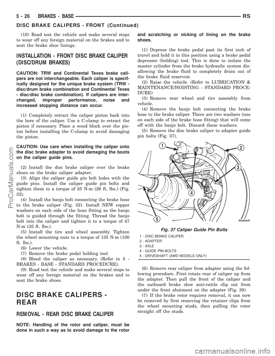
(5) Remove the disc brake caliper to adapter guide
pin bolts (Fig. 37).
(6) Remove rear caliper from adapter using the fol-
lowing procedure. First rotate rear of caliper up from
the adapter. Then pull the front of the caliper and
the outboard brake shoe anti-rattle clip out from
under the front abutment on the adapter (Fig. 38).
(7) If the brake rotor requires removal, it can now
be removed by first removing the retainer clips from
the wheel mounting studs, then pulling the rotor
straight off the studs.
Fig. 37 Caliper Guide Pin Bolts
1 - DISC BRAKE CALIPER
2 - ADAPTER
3 - AXLE
4 - GUIDE PIN BOLTS
5 - DRIVESHAFT (AWD MODELS ONLY)
5 - 26 BRAKES - BASERS
DISC BRAKE CALIPERS - FRONT (Continued)
ProCarManuals.com