2001 DODGE TOWN AND COUNTRY Vacuum
[x] Cancel search: VacuumPage 4 of 2321
VECI LABEL
DESCRIPTION
All models have a Vehicle Emission Control Infor-
mation (VECI) Label. Chrysler permanently attaches
the label in the engine compartment. It cannot be
removed without defacing information and destroying
the label.
The label contains the vehicle's emission specifica-
tions and vacuum hose routings. All hoses must be
connected and routed according to the label.
BODY CODE PLATE
DESCRIPTION
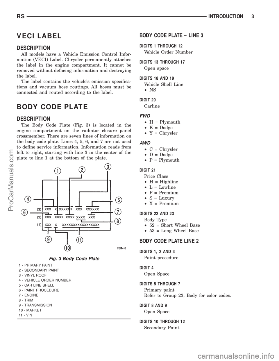
The Body Code Plate (Fig. 3) is located in the
engine compartment on the radiator closure panel
crossmember. There are seven lines of information on
the body code plate. Lines 4, 5, 6, and 7 are not used
to define service information. Information reads from
left to right, starting with line 3 in the center of the
plate to line 1 at the bottom of the plate.
BODY CODE PLATE ± LINE 3
DIGITS 1 THROUGH 12
Vehicle Order Number
DIGITS 13 THROUGH 17
Open space
DIGITS 18 AND 19
Vehicle Shell Line
²NS
DIGIT 20
Carline
FWD
²H = Plymouth
²K = Dodge
²Y = Chrysler
AW D
²C = Chrysler
²D = Dodge
²P = Plymouth
DIGIT 21
Price Class
²H = Highline
²L = Lowline
²P = Premium
²S = Luxury
²X = Premium
DIGITS 22 AND 23
Body Type
²52 = Short Wheel Base
²53 = Long Wheel Base
BODY CODE PLATE LINE 2
DIGITS 1, 2 AND 3
Paint procedure
DIGIT 4
Open Space
DIGITS 5 THROUGH 7
Primary paint
Refer to Group 23, Body for color codes.
DIGIT 8 AND 9
Open Space
DIGITS 10 THROUGH 12
Secondary Paint
Fig. 3 Body Code Plate
1 - PRIMARY PAINT
2 - SECONDARY PAINT
3 - VINYL ROOF
4 - VEHICLE ORDER NUMBER
5 - CAR LINE SHELL
6 - PAINT PROCEDURE
7 - ENGINE
8 - TRIM
9 - TRANSMISSION
10 - MARKET
11 - VIN
RSINTRODUCTION3
ProCarManuals.com
Page 21 of 2321
VEHICLE SAFETY
CERTIFICATION LABEL
DESCRIPTION
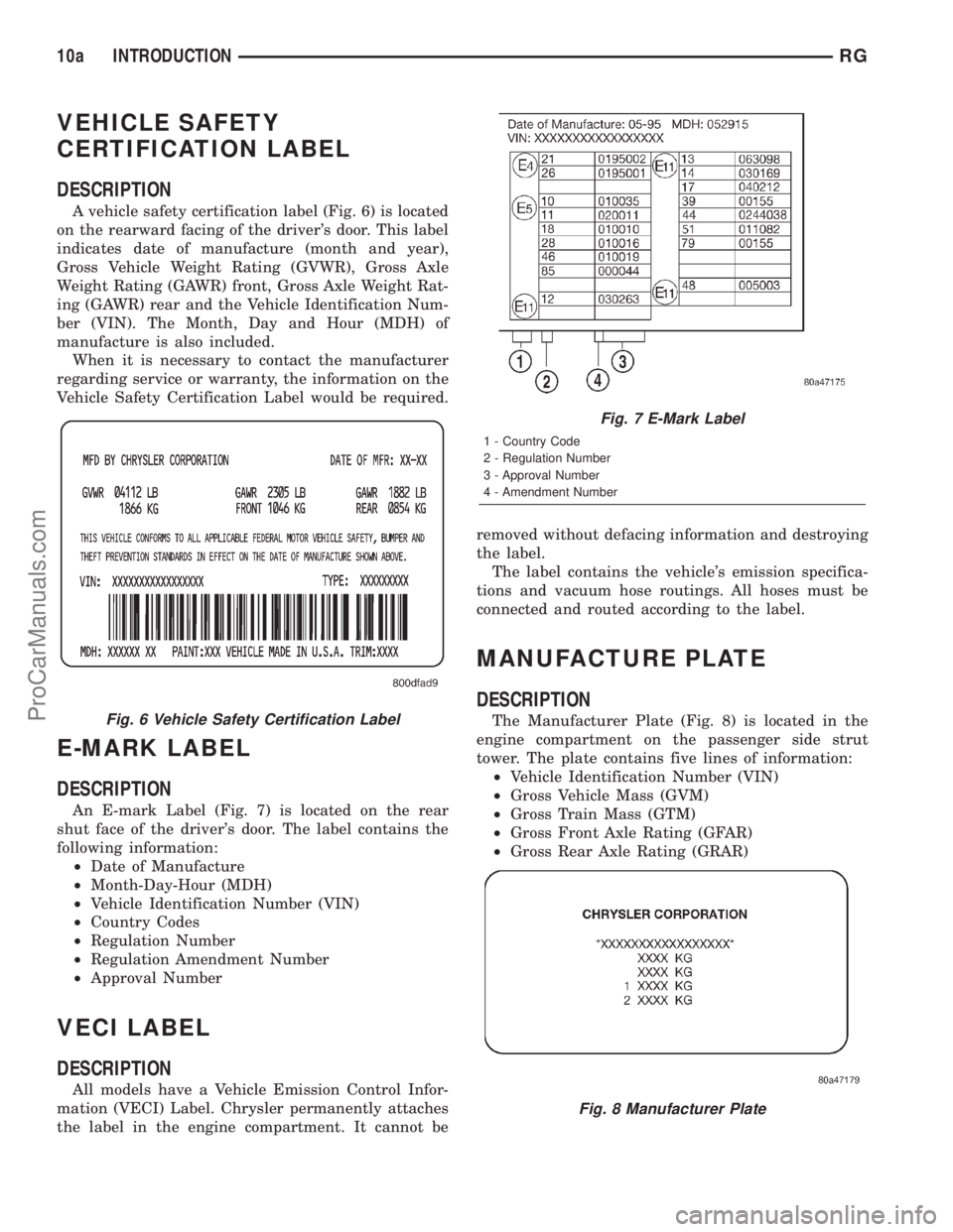
A vehicle safety certification label (Fig. 6) is located
on the rearward facing of the driver's door. This label
indicates date of manufacture (month and year),
Gross Vehicle Weight Rating (GVWR), Gross Axle
Weight Rating (GAWR) front, Gross Axle Weight Rat-
ing (GAWR) rear and the Vehicle Identification Num-
ber (VIN). The Month, Day and Hour (MDH) of
manufacture is also included.
When it is necessary to contact the manufacturer
regarding service or warranty, the information on the
Vehicle Safety Certification Label would be required.
E-MARK LABEL
DESCRIPTION
An E-mark Label (Fig. 7) is located on the rear
shut face of the driver's door. The label contains the
following information:
²Date of Manufacture
²Month-Day-Hour (MDH)
²Vehicle Identification Number (VIN)
²Country Codes
²Regulation Number
²Regulation Amendment Number
²Approval Number
VECI LABEL
DESCRIPTION
All models have a Vehicle Emission Control Infor-
mation (VECI) Label. Chrysler permanently attaches
the label in the engine compartment. It cannot beremoved without defacing information and destroying
the label.
The label contains the vehicle's emission specifica-
tions and vacuum hose routings. All hoses must be
connected and routed according to the label.
MANUFACTURE PLATE
DESCRIPTION
The Manufacturer Plate (Fig. 8) is located in the
engine compartment on the passenger side strut
tower. The plate contains five lines of information:
²Vehicle Identification Number (VIN)
²Gross Vehicle Mass (GVM)
²Gross Train Mass (GTM)
²Gross Front Axle Rating (GFAR)
²Gross Rear Axle Rating (GRAR)Fig. 6 Vehicle Safety Certification Label
Fig. 7 E-Mark Label
1 - Country Code
2 - Regulation Number
3 - Approval Number
4 - Amendment Number
Fig. 8 Manufacturer Plate
10a INTRODUCTIONRG
ProCarManuals.com
Page 161 of 2321
JUNCTION BLOCK
DESCRIPTION...........................32
OPERATION.............................32
REMOVAL..............................32
INSTALLATION...........................33
MASTER CYLINDER
DESCRIPTION...........................33
OPERATION.............................34
STANDARD PROCEDURE..................34
MASTER CYLINDER BLEEDING...........34
REMOVAL..............................34
DISASSEMBLY...........................35
ASSEMBLY.............................36
INSTALLATION...........................36
POWER BRAKE BOOSTER
DESCRIPTION...........................37
OPERATION.............................37
DIAGNOSIS AND TESTING.................38
POWER BRAKE BOOSTER...............38
REMOVAL..............................38
INSTALLATION...........................40
PROPORTIONING VALVE
DESCRIPTION...........................41
OPERATION.............................42
DIAGNOSIS AND TESTING.................42
PROPORTIONING VALVE (HEIGHT
SENSING).............................42
REMOVAL..............................43
INSTALLATION...........................43
ROTORS
DIAGNOSIS AND TESTING.................44BRAKE ROTOR........................44
STANDARD PROCEDURE..................47
BRAKE ROTOR MACHINING..............47
REMOVAL..............................48
INSTALLATION...........................48
SUPPORT PLATE - DRUM BRAKE
REMOVAL..............................48
INSTALLATION...........................49
WHEEL CYLINDERS
REMOVAL..............................50
INSPECTION............................50
INSTALLATION...........................50
PARKING BRAKE
DESCRIPTION...........................50
OPERATION.............................51
STANDARD PROCEDURE..................51
PARKING BRAKE AUTOMATIC ADJUSTER
MECHANISM RELEASE..................51
PARKING BRAKE AUTOMATIC ADJUSTER
RESET...............................51
LEVER - PARKING BRAKE
REMOVAL..............................52
INSTALLATION...........................53
SHOES - PARKING BRAKE
REMOVAL..............................53
INSTALLATION...........................58
ADJUSTMENTS..........................59
CABLES - PARKING BRAKE
REMOVAL..............................61
INSTALLATION...........................65
ADJUSTMENTS..........................66
BRAKES - BASE
DESCRIPTION - BASE BRAKES
The base brake system consists of the following
components:
²Brake pedal
²Power brake booster
²Master cylinder
²Brake tubes and hoses
²Proportioning valve (non-ABS vehicles only)
²Disc brakes
²Drum brakes
²Brake lamp switch
²Brake fluid level switch
²Parking brakes
Front disc brakes control the braking of the front
wheels; rear braking is controlled by rear drum
brakes or rear disc brakes depending on options.
The hydraulic brake system is diagonally split on
both the non-antilock braking systems and antilock
braking systems. That means the left front and right
rear brakes are on one hydraulic circuit and the right
front and left rear are on the other.For information on the brake lamp switch, (Refer
to 8 - ELECTRICAL/LAMPS/LIGHTING - EXTERI-
OR/BRAKE LAMP SWITCH - DESCRIPTION)
Vehicles equipped with the optional antilock brake
system (ABS) use a system designated Mark 20e. It
is available with or without traction control. This
system shares most base brake hardware used on
vehicles without ABS. ABS components are described
in detail in ANTILOCK BRAKE SYSTEM.
OPERATION - BASE BRAKES
When a vehicle needs to be stopped, the driver
applies the brake pedal. The brake pedal pushes the
input rod of the power brake booster into the booster.
The booster uses vacuum to ease pedal effort as force
is transferred through the booster to the master cyl-
inder. The booster's output rod pushes in the master
cylinder's primary and secondary pistons applying
hydraulic pressure through the chassis brake tubes
to the brakes at each tire and wheel assembly.
The parking brakes are foot-operated. When
applied, the parking brake lever pulls on cables that
actuate brake shoes at each rear wheel. These shoes
come in contact with a hub mounted drum (drum for
5 - 2 BRAKES - BASERS
ProCarManuals.com
Page 164 of 2321
CONDITION POSSIBLE CAUSES CORRECTION
SCRAPING (METAL-TO-
METAL).1. Foreign object interference with
brakes.1. Inspect brakes and remove foreign
object.
2. Brake shoes worn out. 2. Replace brake shoes. Inspect rotors and
drums. Reface or replace as necessary.
OTHER BRAKE CONDITIONS
CONDITION POSSIBLE CAUSES CORRECTION
BRAKES CHATTER 1. Rear brake drum out of round or
disc brake rotor has excessive
thickness variation.1. Isolate condition as rear or front.
Reface or replace brake drums or
rotors as necessary.
BRAKES DRAG (FRONT
OR ALL)1. Contaminated brake fluid. 1. Check for swollen seals. Replace all
system components containing rubber.
2. Binding caliper pins or bushings. 2. Replace pins and bushings.
3. Binding master cylinder. 3. Replace master cylinder.
4. Binding brake pedal. 4. Replace brake pedal.
5. Brake lamp switch not adjusted
properly and mounting bracket is bent.5. Straighten mounting bracket and
replace brake lamp switch.
BRAKES DRAG (REAR
ONLY)1. Parking brake cables binding or
froze up.1. Check cable routing. Replace cables
as necessary.
2. Parking brake cable return spring
not returning shoes.2. Replace cables as necessary.
3. Service brakes not adjusted
properly (rear drum brakes only).3. Follow the procedure listed in the
adjustment section.
4. Rear disc brake parking brake not
properly adjusted.Adjust parking brake shoes.
BRAKES GRAB 1. Contaminated brake shoe linings. 1. Inspect and clean, or replace shoes.
Repair source of contamination.
2. Improper power brake booster
assist.2. Refer to power brake booster
diagnosis and testing.
EXCESSIVE PEDAL
EFFORT1. Obstruction of brake pedal. 1. Inspect, remove or move obstruction.
2. Low power brake booster assist
(vacuum leak).2. Refer to power brake booster
diagnosis and testing.
3. Glazed brake linings. 3. Reface or replace brake rotors as
necessary. Replace brake shoes.
4. Brake shoe lining transfer to brake
rotor.4. Reface or replace brake rotors as
necessary. Replace brake shoes.
EXCESSIVE PEDAL
TRAVEL (VEHICLE
STOPS OK)1. Air in brake lines. 1. Bleed brakes.
2. Rear drum brake auto-adjuster
malfunctioning.2. Inspect and replace drum brake
components as necessary. Adjust rear
brakes.
RSBRAKES - BASE5-5
BRAKES - BASE (Continued)
ProCarManuals.com
Page 165 of 2321
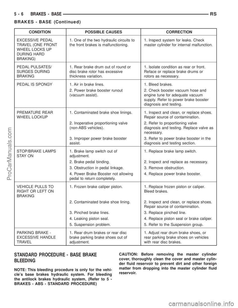
CONDITION POSSIBLE CAUSES CORRECTION
EXCESSIVE PEDAL
TRAVEL (ONE FRONT
WHEEL LOCKS UP
DURING HARD
BRAKING)1. One of the two hydraulic circuits to
the front brakes is malfunctioning.1. Inspect system for leaks. Check
master cylinder for internal malfunction.
PEDAL PULSATES/
SURGES DURING
BRAKING1. Rear brake drum out of round or
disc brake rotor has excessive
thickness variation.1. Isolate condition as rear or front.
Reface or replace brake drums or
rotors as necessary.
PEDAL IS SPONGY 1. Air in brake lines. 1. Bleed brakes.
2. Power brake booster runout
(vacuum assist).2. Check booster vacuum hose and
engine tune for adequate vacuum
supply. Refer to power brake booster
diagnosis and testing.
PREMATURE REAR
WHEEL LOCKUP1. Contaminated brake shoe linings. 1. Inspect and clean, or replace shoes.
Repair source of contamination.
2. Inoperative proportioning valve
(non-ABS vehicles).2. Refer to proportioning valve
diagnosis and testing. Replace valve as
necessary.
3. Improper power brake booster
assist.3. Refer to power brake booster in the
diagnosis and testing section.
STOP/BRAKE LAMPS
S TAY O N1. Brake lamp switch out of
adjustment.1. Replace brake lamp switch.
2. Brake pedal binding. 2. Inspect and replace as necessary.
3. Obstruction in pedal linkage. 3. Remove obstruction.
4. Power Brake Booster not allowing
pedal to return completely.4. Replace power brake booster.
VEHICLE PULLS TO
RIGHT OR LEFT ON
BRAKING1. Frozen brake caliper piston. 1. Replace frozen piston or caliper.
Bleed brakes.
2. Contaminated brake shoe lining. 2. Inspect and clean, or replace shoes.
Repair source of contamination.
3. Pinched brake lines. 3. Replace pinched line.
4. Leaking piston seal. 4. Replace piston seal or brake caliper.
5. Suspension problem. 5. Refer to the Suspension group.
PARKING BRAKE -
EXCESSIVE HANDLE
TRAVEL1. Rear drum brakes or rear disc
brake parking brake shoes out of
adjustment.1. Adjust rear drum brake shoes, or
rear parking brake shoes on vehicles
with rear disc brakes.
STANDARD PROCEDURE - BASE BRAKE
BLEEDING
NOTE: This bleeding procedure is only for the vehi-
cle's base brakes hydraulic system. For bleeding
the antilock brakes hydraulic system, (Refer to 5 -
BRAKES - ABS - STANDARD PROCEDURE)CAUTION: Before removing the master cylinder
cover, thoroughly clean the cover and master cylin-
der fluid reservoir to prevent dirt and other foreign
matter from dropping into the master cylinder fluid
reservoir.
5 - 6 BRAKES - BASERS
BRAKES - BASE (Continued)
ProCarManuals.com
Page 191 of 2321
STANDARD PROCEDURE - BRAKE FLUID
LEVEL CHECKING
Check master cylinder reservoir fluid level a mini-
mum of twice annually.
Fluid reservoirs are marked with the words FULL
and ADD to indicate proper brake fluid fill level of
the master cylinder.
If necessary, add brake fluid to bring the level to
the bottom of the FULL mark on the side of the mas-
ter cylinder fluid reservoir.
Use only Mopartbrake fluid or equivalent from a
sealed container. Brake fluid must conform to DOT 3
specifications (DOT 4 or DOT 4+ are acceptable).
DO NOTuse brake fluid with a lower boiling
point, as brake failure could result during prolonged
hard braking.
Use only brake fluid that was stored in a tightly-
sealed container.
DO NOTuse petroleum-based fluid because seal
damage will result. Petroleum based fluids would be
items such as engine oil, transmission fluid, power
steering fluid etc.
SPECIFICATIONS
BRAKE FLUID
The brake fluid used in this vehicle must conform
to DOT 3 specifications (DOT 4 and DOT 4+ are
acceptable) and SAE J1703 standards. No other type
of brake fluid is recommended or approved for usage
in the vehicle brake system. Use only MopartBrake
Fluid or equivalent from a tightly sealed container.
CAUTION: Never use reclaimed brake fluid or fluid
from an container which has been left open. An
open container of brake fluid will absorb moisture
from the air and contaminate the fluid.
CAUTION: Never use any type of a petroleum-based
fluid in the brake hydraulic system. Use of such
type fluids will result in seal damage of the vehicle
brake hydraulic system causing a failure of the
vehicle brake system. Petroleum based fluids would
be items such as engine oil, transmission fluid,
power steering fluid, etc.
JUNCTION BLOCK
DESCRIPTION - NON-ABS JUNCTION BLOCK
A junction block is used on vehicles that are not
equipped with antilock brakes (ABS). The junction
block mounts in the same location as the integrated
control unit (ICU) does on vehicles equipped withABS. This allows for use of the same brake tube con-
figuration on all vehicles. The junction block is
located on the driver's side of the front suspension
cradle/crossmember below the master cylinder (Fig.
46).
It has six threaded ports to which the brake tubes
connect. Two are for the primary and secondary
brake tubes coming from the master cylinder. The
remaining four are for the chassis brake tubes going
to each brake assembly.
OPERATION - NON-ABS JUNCTION BLOCK
The junction block distributes the brake fluid com-
ing from the master cylinder primary and secondary
ports to the four chassis brake tubes leading to the
brakes at each wheel. Since the junction block
mounts in the same location as the ABS integrated
control unit (ICU), it allows for the common use of
brake tubes going to the brakes whether the vehicle
is equipped with or without ABS.
NOTE: Although the brake tubes coming from the
master cylinder to the junction block or ABS ICU
may appear to be the same, they are not. They are
unique to each brake system application.
REMOVAL - NON-ABS JUNCTION BLOCK
(1) Using a brake pedal depressor, move and lock
the brake pedal to a position past its first 1 inch of
travel. This will prevent brake fluid from draining
out of the master cylinder when the brake tubes are
removed from the junction block.
(2) Disconnect the battery negative cable.
(3) If the vehicle is equipped with speed control,
perform the following:
(a) Disconnect the battery positive cable.
(b) Remove the battery (Refer to 8 - ELECTRI-
CAL/BATTERY SYSTEM/BATTERY - REMOVAL).
(c) Disconnect the vacuum hose connector at the
tank built into the battery tray.
(d) Remove the screw securing the coolant filler
neck to the battery tray.
(e) Remove the battery tray (Refer to 8 - ELEC-
TRICAL/BATTERY SYSTEM/TRAY - REMOVAL).
(f) Remove the fasteners and move the speed
control servo off to the side, out of the way.
CAUTION: Before removing the brake tubes from
the junction block, the junction block and the brake
tubes must be thoroughly cleaned. This is required
to prevent contamination from entering the brake
hydraulic system.
5 - 32 BRAKES - BASERS
FLUID (Continued)
ProCarManuals.com
Page 192 of 2321
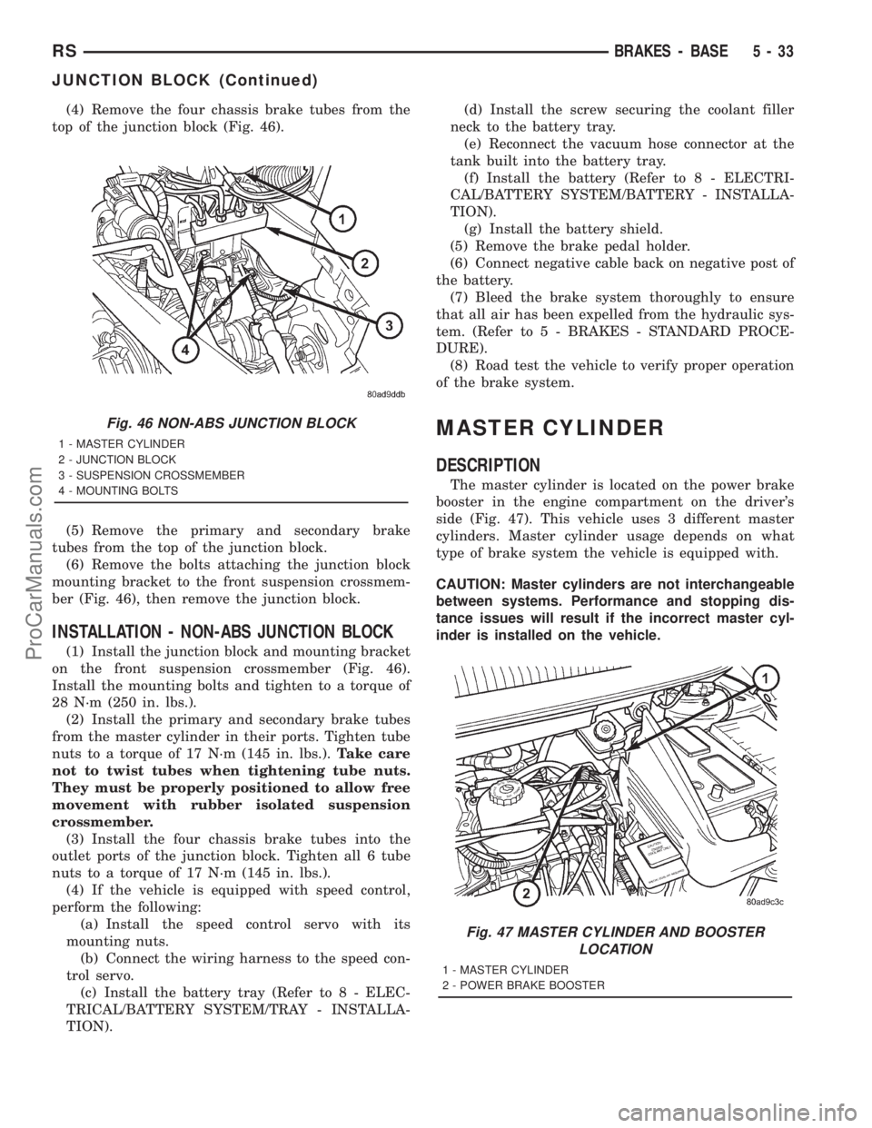
(4) Remove the four chassis brake tubes from the
top of the junction block (Fig. 46).
(5) Remove the primary and secondary brake
tubes from the top of the junction block.
(6) Remove the bolts attaching the junction block
mounting bracket to the front suspension crossmem-
ber (Fig. 46), then remove the junction block.
INSTALLATION - NON-ABS JUNCTION BLOCK
(1) Install the junction block and mounting bracket
on the front suspension crossmember (Fig. 46).
Install the mounting bolts and tighten to a torque of
28 N´m (250 in. lbs.).
(2) Install the primary and secondary brake tubes
from the master cylinder in their ports. Tighten tube
nuts to a torque of 17 N´m (145 in. lbs.).Take care
not to twist tubes when tightening tube nuts.
They must be properly positioned to allow free
movement with rubber isolated suspension
crossmember.
(3) Install the four chassis brake tubes into the
outlet ports of the junction block. Tighten all 6 tube
nuts to a torque of 17 N´m (145 in. lbs.).
(4) If the vehicle is equipped with speed control,
perform the following:
(a) Install the speed control servo with its
mounting nuts.
(b) Connect the wiring harness to the speed con-
trol servo.
(c) Install the battery tray (Refer to 8 - ELEC-
TRICAL/BATTERY SYSTEM/TRAY - INSTALLA-
TION).(d) Install the screw securing the coolant filler
neck to the battery tray.
(e) Reconnect the vacuum hose connector at the
tank built into the battery tray.
(f) Install the battery (Refer to 8 - ELECTRI-
CAL/BATTERY SYSTEM/BATTERY - INSTALLA-
TION).
(g) Install the battery shield.
(5) Remove the brake pedal holder.
(6) Connect negative cable back on negative post of
the battery.
(7) Bleed the brake system thoroughly to ensure
that all air has been expelled from the hydraulic sys-
tem. (Refer to 5 - BRAKES - STANDARD PROCE-
DURE).
(8) Road test the vehicle to verify proper operation
of the brake system.
MASTER CYLINDER
DESCRIPTION
The master cylinder is located on the power brake
booster in the engine compartment on the driver's
side (Fig. 47). This vehicle uses 3 different master
cylinders. Master cylinder usage depends on what
type of brake system the vehicle is equipped with.
CAUTION: Master cylinders are not interchangeable
between systems. Performance and stopping dis-
tance issues will result if the incorrect master cyl-
inder is installed on the vehicle.
Fig. 46 NON-ABS JUNCTION BLOCK
1 - MASTER CYLINDER
2 - JUNCTION BLOCK
3 - SUSPENSION CROSSMEMBER
4 - MOUNTING BOLTS
Fig. 47 MASTER CYLINDER AND BOOSTER
LOCATION
1 - MASTER CYLINDER
2 - POWER BRAKE BOOSTER
RSBRAKES - BASE5-33
JUNCTION BLOCK (Continued)
ProCarManuals.com
Page 193 of 2321
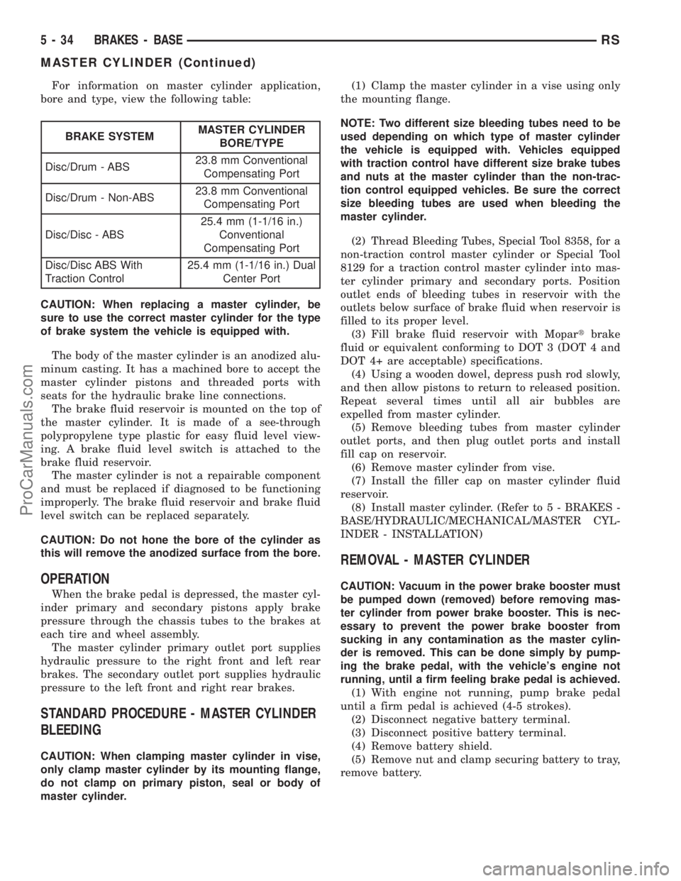
For information on master cylinder application,
bore and type, view the following table:
BRAKE SYSTEMMASTER CYLINDER
BORE/TYPE
Disc/Drum - ABS23.8 mm Conventional
Compensating Port
Disc/Drum - Non-ABS23.8 mm Conventional
Compensating Port
Disc/Disc - ABS25.4 mm (1-1/16 in.)
Conventional
Compensating Port
Disc/Disc ABS With
Traction Control25.4 mm (1-1/16 in.) Dual
Center Port
CAUTION: When replacing a master cylinder, be
sure to use the correct master cylinder for the type
of brake system the vehicle is equipped with.
The body of the master cylinder is an anodized alu-
minum casting. It has a machined bore to accept the
master cylinder pistons and threaded ports with
seats for the hydraulic brake line connections.
The brake fluid reservoir is mounted on the top of
the master cylinder. It is made of a see-through
polypropylene type plastic for easy fluid level view-
ing. A brake fluid level switch is attached to the
brake fluid reservoir.
The master cylinder is not a repairable component
and must be replaced if diagnosed to be functioning
improperly. The brake fluid reservoir and brake fluid
level switch can be replaced separately.
CAUTION: Do not hone the bore of the cylinder as
this will remove the anodized surface from the bore.
OPERATION
When the brake pedal is depressed, the master cyl-
inder primary and secondary pistons apply brake
pressure through the chassis tubes to the brakes at
each tire and wheel assembly.
The master cylinder primary outlet port supplies
hydraulic pressure to the right front and left rear
brakes. The secondary outlet port supplies hydraulic
pressure to the left front and right rear brakes.
STANDARD PROCEDURE - MASTER CYLINDER
BLEEDING
CAUTION: When clamping master cylinder in vise,
only clamp master cylinder by its mounting flange,
do not clamp on primary piston, seal or body of
master cylinder.(1) Clamp the master cylinder in a vise using only
the mounting flange.
NOTE: Two different size bleeding tubes need to be
used depending on which type of master cylinder
the vehicle is equipped with. Vehicles equipped
with traction control have different size brake tubes
and nuts at the master cylinder than the non-trac-
tion control equipped vehicles. Be sure the correct
size bleeding tubes are used when bleeding the
master cylinder.
(2) Thread Bleeding Tubes, Special Tool 8358, for a
non-traction control master cylinder or Special Tool
8129 for a traction control master cylinder into mas-
ter cylinder primary and secondary ports. Position
outlet ends of bleeding tubes in reservoir with the
outlets below surface of brake fluid when reservoir is
filled to its proper level.
(3) Fill brake fluid reservoir with Mopartbrake
fluid or equivalent conforming to DOT 3 (DOT 4 and
DOT 4+ are acceptable) specifications.
(4) Using a wooden dowel, depress push rod slowly,
and then allow pistons to return to released position.
Repeat several times until all air bubbles are
expelled from master cylinder.
(5) Remove bleeding tubes from master cylinder
outlet ports, and then plug outlet ports and install
fill cap on reservoir.
(6) Remove master cylinder from vise.
(7) Install the filler cap on master cylinder fluid
reservoir.
(8) Install master cylinder. (Refer to 5 - BRAKES -
BASE/HYDRAULIC/MECHANICAL/MASTER CYL-
INDER - INSTALLATION)
REMOVAL - MASTER CYLINDER
CAUTION: Vacuum in the power brake booster must
be pumped down (removed) before removing mas-
ter cylinder from power brake booster. This is nec-
essary to prevent the power brake booster from
sucking in any contamination as the master cylin-
der is removed. This can be done simply by pump-
ing the brake pedal, with the vehicle's engine not
running, until a firm feeling brake pedal is achieved.
(1) With engine not running, pump brake pedal
until a firm pedal is achieved (4-5 strokes).
(2) Disconnect negative battery terminal.
(3) Disconnect positive battery terminal.
(4) Remove battery shield.
(5) Remove nut and clamp securing battery to tray,
remove battery.
5 - 34 BRAKES - BASERS
MASTER CYLINDER (Continued)
ProCarManuals.com