Page 1787 of 2321
OPERATION
NOTE: Refer to the Hydraulic Schematics for a
visual aid in determining valve location, operation
and design.
REGULATOR VALVE
The regulator valve controls hydraulic pressure in
the transaxle. It receives unregulated pressure from
the pump, which works against spring tension to
maintain oil at specific pressures. A system of sleeves
and ports allows the regulator valve to work at one of
three predetermined pressure levels. Regulated oil
pressure is also referred to as ªline pressure.º
SOLENOID SWITCH VALVE
The solenoid switch valve controls line pressure
from the LR/CC solenoid. In one position, it allows
the low/reverse clutch to be pressurized. In the other,
it directs line pressure to the converter control and
converter clutch valves.
MANUAL VALVE
The manual valve is operated by the mechanical
shift linkage. Its primary responsibility is to send
line pressure to the appropriate hydraulic circuits
and solenoids. The valve has three operating ranges
or positions.
CONVERTER CLUTCH SWITCH VALVE
The main responsibility of the converter clutch
switch valve is to control hydraulic pressure applied
to the front (off) side of the converter clutch piston.
Line pressure from the regulator valve is fed to the
torque converter regulator valve, where it passes
through the valve, and is slightly regulated. The
pressure is then directed to the converter clutch
switch valve and to the front side of the converter
clutch piston. This pressure pushes the piston back
and disengages the converter clutch.
CONVERTER CLUTCH CONTROL VALVE
The converter clutch control valve controls the
back (on) side of the torque converter clutch. When
the TCM energizes or modulates the LR/CC solenoid
to apply the converter clutch piston, both the con-
verter clutch control valve and the converter control
valve move, allowing pressure to be applied to the
back side of the clutch.
T/C REGULATOR VALVE
The torque converter regulator valve slightly regu-
lates the flow of fluid to the torque converter.
LOW/REVERSE SWITCH VALVE
The low/reverse clutch is applied from different
sources, depending on whether low (1st) gear or
reverse is selected. The low/reverse switch valve
alternates positions depending on from which direc-
tion fluid pressure is applied. By design, when the
valve is shifted by fluid pressure from one channel,
the opposing channel is blocked. The switch valve
alienates the possibility of a sticking ball check, thus
providing consistent application of the low/reverse
clutch under all operating conditions.
REMOVAL
NOTE: If valve body is replaced or reconditioned,
the TCM Quick Learn Procedure must be per-
formed. (Refer to 8 - ELECTRICAL/ELECTRONIC
CONTROL MODULES/TRANSMISSION CONTROL
MODULE - STANDARD PROCEDURE)
(1) Disconnect battery negative cable.
(2) Disconnect gearshift cable from manual valve
lever.
(3) Remove manual valve lever from manual shaft.
(4) Raise vehicle on hoist.
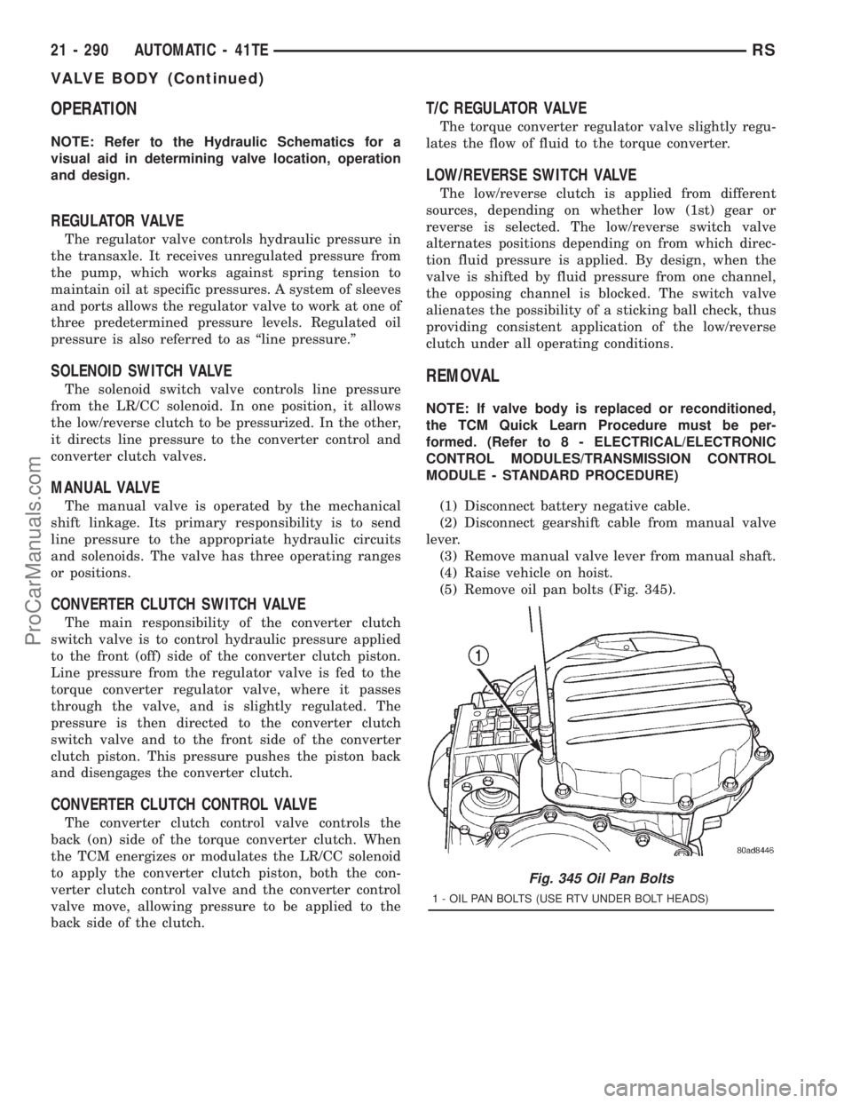
(5) Remove oil pan bolts (Fig. 345).
Fig. 345 Oil Pan Bolts
1 - OIL PAN BOLTS (USE RTV UNDER BOLT HEADS)
21 - 290 AUTOMATIC - 41TERS
VALVE BODY (Continued)
ProCarManuals.com
Page 1799 of 2321
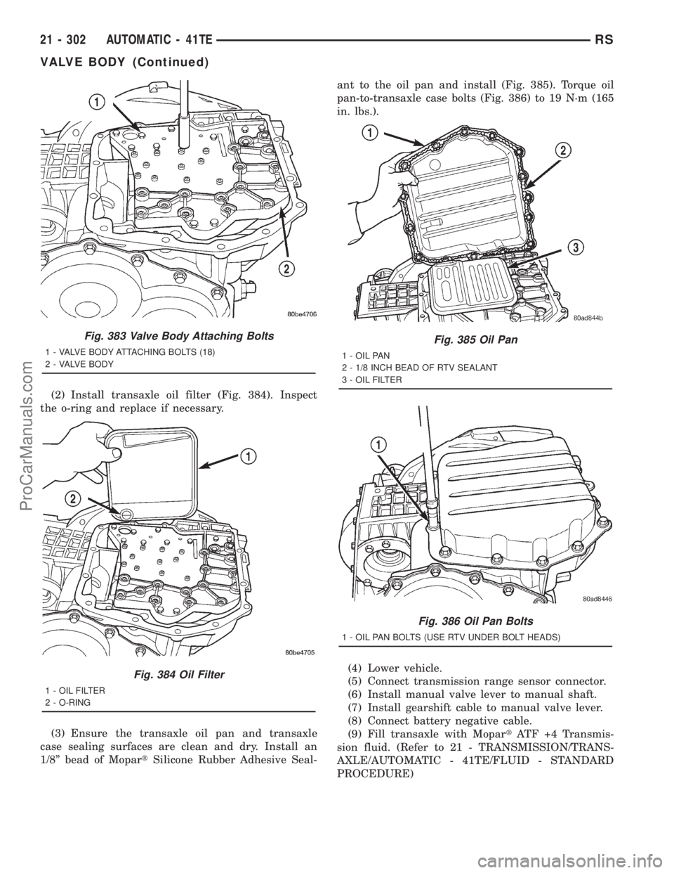
(2) Install transaxle oil filter (Fig. 384). Inspect
the o-ring and replace if necessary.
(3) Ensure the transaxle oil pan and transaxle
case sealing surfaces are clean and dry. Install an
1/8º bead of MopartSilicone Rubber Adhesive Seal-ant to the oil pan and install (Fig. 385). Torque oil
pan-to-transaxle case bolts (Fig. 386) to 19 N´m (165
in. lbs.).
(4) Lower vehicle.
(5) Connect transmission range sensor connector.
(6) Install manual valve lever to manual shaft.
(7) Install gearshift cable to manual valve lever.
(8) Connect battery negative cable.
(9) Fill transaxle with MopartATF +4 Transmis-
sion fluid. (Refer to 21 - TRANSMISSION/TRANS-
AXLE/AUTOMATIC - 41TE/FLUID - STANDARD
PROCEDURE)
Fig. 383 Valve Body Attaching Bolts
1 - VALVE BODY ATTACHING BOLTS (18)
2 - VALVE BODY
Fig. 384 Oil Filter
1 - OIL FILTER
2 - O-RING
Fig. 385 Oil Pan
1 - OIL PAN
2 - 1/8 INCH BEAD OF RTV SEALANT
3 - OIL FILTER
Fig. 386 Oil Pan Bolts
1 - OIL PAN BOLTS (USE RTV UNDER BOLT HEADS)
21 - 302 AUTOMATIC - 41TERS
VALVE BODY (Continued)
ProCarManuals.com
Page 1836 of 2321
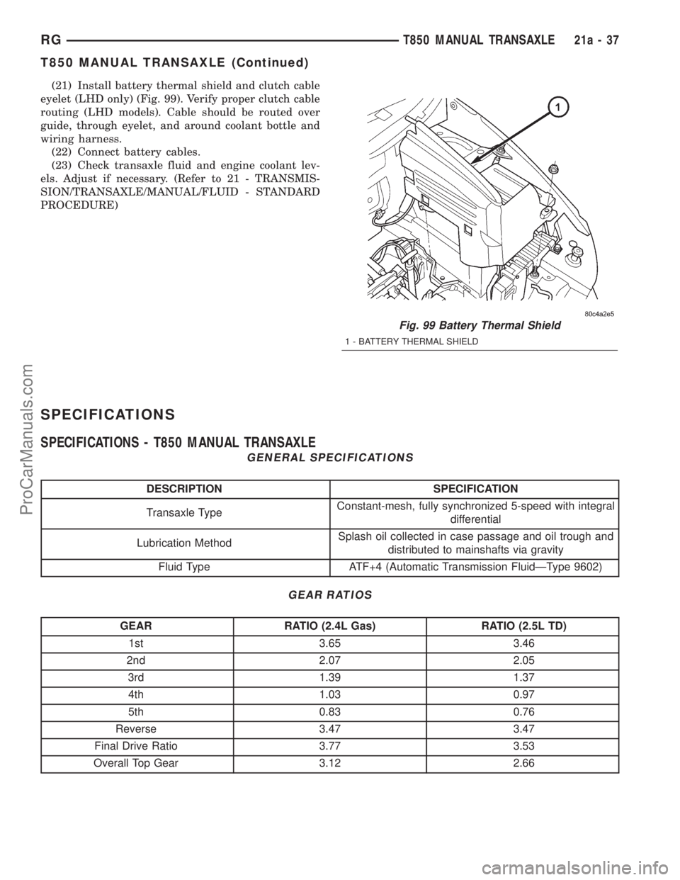
(21) Install battery thermal shield and clutch cable
eyelet (LHD only) (Fig. 99). Verify proper clutch cable
routing (LHD models). Cable should be routed over
guide, through eyelet, and around coolant bottle and
wiring harness.
(22) Connect battery cables.
(23) Check transaxle fluid and engine coolant lev-
els. Adjust if necessary. (Refer to 21 - TRANSMIS-
SION/TRANSAXLE/MANUAL/FLUID - STANDARD
PROCEDURE)
SPECIFICATIONS
SPECIFICATIONS - T850 MANUAL TRANSAXLE
GENERAL SPECIFICATIONS
DESCRIPTION SPECIFICATION
Transaxle TypeConstant-mesh, fully synchronized 5-speed with integral
differential
Lubrication MethodSplash oil collected in case passage and oil trough and
distributed to mainshafts via gravity
Fluid Type ATF+4 (Automatic Transmission FluidÐType 9602)
GEAR RATIOS
GEAR RATIO (2.4L Gas) RATIO (2.5L TD)
1st 3.65 3.46
2nd 2.07 2.05
3rd 1.39 1.37
4th 1.03 0.97
5th 0.83 0.76
Reverse 3.47 3.47
Final Drive Ratio 3.77 3.53
Overall Top Gear 3.12 2.66
Fig. 99 Battery Thermal Shield
1 - BATTERY THERMAL SHIELD
RGT850 MANUAL TRANSAXLE21a-37
T850 MANUAL TRANSAXLE (Continued)
ProCarManuals.com
Page 1851 of 2321
ADJUSTMENT - DIFFERENTIAL SIDE GEAR
END PLAY
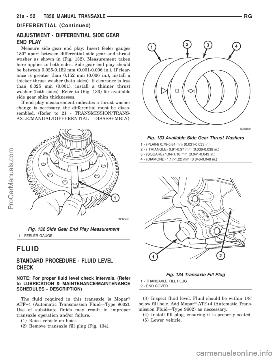
Measure side gear end play: Insert feeler gauges
180É apart between differential side gear and thrust
washer as shown in (Fig. 132). Measurement taken
here applies to both sides. Side gear end play should
be between 0.025-0.152 mm (0.001-0.006 in.). If clear-
ance is greater than 0.152 mm (0.006 in.), install a
thicker thrust washer (both sides). If clearance is less
than 0.025 mm (0.001), install a thinner thrust
washer (both sides). Refer to (Fig. 133) for available
side gear shim thicknesses.
If end play measurement indicates a thrust washer
change is necessary, the differential must be disas-
sembled. (Refer to 21 - TRANSMISSION/TRANS-
AXLE/MANUAL/DIFFERENTIAL - DISASSEMBLY)
FLUID
STANDARD PROCEDURE - FLUID LEVEL
CHECK
NOTE: For proper fluid level check intervals, (Refer
to LUBRICATION & MAINTENANCE/MAINTENANCE
SCHEDULES - DESCRIPTION)
The fluid required in this transaxle is Mopart
ATF+4 (Automatic Transmission FluidÐType 9602).
Use of substitute fluids may result in improper
transaxle operation and/or failure.
(1) Raise vehicle on hoist.
(2) Remove transaxle fill plug (Fig. 134).(3) Inspect fluid level. Fluid should be within 1/8º
below fill hole. Add MopartATF+4 (Automatic Trans-
mission FluidÐType 9602) as neccessary.
(4) Install fill plug, ensuring it is properly seated.
(5) Lower vehicle.
Fig. 132 Side Gear End Play Measurement
1 - FEELER GAUGE
Fig. 133 Available Side Gear Thrust Washers
1 - (PLAIN) 0.79-0.84 mm (0.031-0.033 in.)
2 - ( TRIANGLE) 0.91-0.97 mm (0.036-0.038 in.)
3 - (SQUARE) 1.04-1.10 mm (0.041-0.043 in.)
4 - (DIAMOND) 1.17-1.22 mm (0.046-0.048 in.)
Fig. 134 Transaxle Fill Plug
1 - TRANSAXLE FILL PLUG
2 - END COVER
21a - 52 T850 MANUAL TRANSAXLERG
DIFFERENTIAL (Continued)
ProCarManuals.com
Page 1852 of 2321
STANDARD PROCEDURE - FLUID DRAIN AND
FILL
NOTE: For proper fluid change intervals, (Refer to
LUBRICATION & MAINTENANCE/MAINTENANCE
SCHEDULES - DESCRIPTION)
The fluid required in this transaxle is Mopart
ATF+4 (Automatic Transmission FluidÐType 9602).
Use of substitute fluids may result in improper
transaxle operation and/or failure.
FLUID DRAIN
(1) Raise vehicle on hoist.
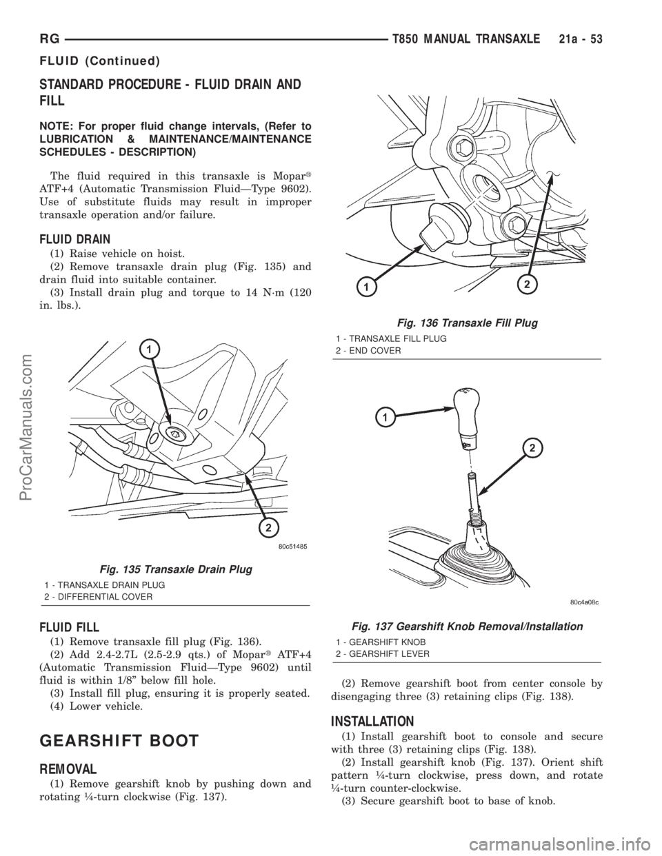
(2) Remove transaxle drain plug (Fig. 135) and
drain fluid into suitable container.
(3) Install drain plug and torque to 14 N´m (120
in. lbs.).
FLUID FILL
(1) Remove transaxle fill plug (Fig. 136).
(2) Add 2.4-2.7L (2.5-2.9 qts.) of MopartATF+4
(Automatic Transmission FluidÐType 9602) until
fluid is within 1/8º below fill hole.
(3) Install fill plug, ensuring it is properly seated.
(4) Lower vehicle.
GEARSHIFT BOOT
REMOVAL
(1) Remove gearshift knob by pushing down and
rotating ò-turn clockwise (Fig. 137).(2) Remove gearshift boot from center console by
disengaging three (3) retaining clips (Fig. 138).
INSTALLATION
(1) Install gearshift boot to console and secure
with three (3) retaining clips (Fig. 138).
(2) Install gearshift knob (Fig. 137). Orient shift
pattern ò-turn clockwise, press down, and rotate
ò-turn counter-clockwise.
(3) Secure gearshift boot to base of knob.
Fig. 135 Transaxle Drain Plug
1 - TRANSAXLE DRAIN PLUG
2 - DIFFERENTIAL COVER
Fig. 136 Transaxle Fill Plug
1 - TRANSAXLE FILL PLUG
2 - END COVER
Fig. 137 Gearshift Knob Removal/Installation
1 - GEARSHIFT KNOB
2 - GEARSHIFT LEVER
RGT850 MANUAL TRANSAXLE21a-53
FLUID (Continued)
ProCarManuals.com