2001 DODGE TOWN AND COUNTRY wheel bolt torque
[x] Cancel search: wheel bolt torquePage 590 of 2321
INSTALLATION
(1) Position second row seat belt retractor in vehi-
cle.
(2) Install screw attaching retractor to inner quar-
ter panel.
(3) Install bolt attaching retractor to inner quarter
panel. Tightening specifications for all seat belt bolts
is 39 N´m (29 ft. lbs.) torque.
(4) Route seat belt webbing and turning loop
through access hole in quarter trim.
(5) Install quarter trim bolster.
(6) Install D-pillar trim panel.
(7) Position turning loop to extension bracket.
(8) Install bolt attaching turning loop to extension
bracket above quarter glass. Tightening specifications
for all seat belt bolts is 39 N´m (29 ft. lbs.) torque.
(9) Install upper turning loop extension cover.
(10) Position lower anchor to wheelhouse.
(11) Install lower anchor shoulder-nut. Tightening
shoulder nut to 39 N´m (29 ft. lbs.) torque.
(12) Install lower anchor cover over the anchor
shoulder-nut.(13) Install second row seat to vehicle. Refer to
Owner's Manual for proper procedures.
SEAT BELT SECOND RIGHT
ROW OUTBOARD - LBW WITH
REAR HVAC
REMOVAL
(1) Remove second row seat from vehicle. Refer to
Owner's Manual for proper procedures.
(2) Slide lower anchor cover from over the anchor
shoulder-nut.
(3) Remove lower anchor shoulder-nut.
(4) Remove lower anchor from wheelhouse.
(5) Fold upper turning loop extension cover down-
ward to gain access to anchor bolt.
(6) Remove bolt attaching turning loop to exten-
sion bracket above quarter glass.
(7) Remove turning loop from extension bracket.
(8) Remove D-pillar trim panel.
(9) Remove quarter trim bolster.
(10) Remove quarter trim panel as necessary to
gain access to HVAC unit.
(11) Route seat belt webbing and turning loop
through access hole in quarter trim.
(12) Loosen HVAC unit enough to gain access to
seat belt retractor fasteners.
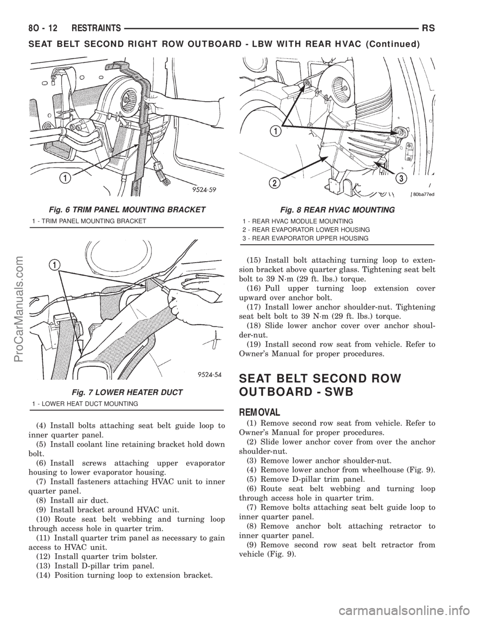
(a) Remove bracket around HVAC unit (Fig. 6).
(b) Remove air duct (Fig. 7).
(c) Remove fasteners attaching HVAC unit to
inner quarter panel (Fig. 8).
(d) Remove screws attaching upper evaporator
housing to lower evaporator housing.
(e) Remove coolant line retaining bracket hold
down bolt.
(13) Remove bolts attaching seat belt guide loop to
inner quarter panel.
(14) Pull outward on HVAC unit and remove bolt
attaching retractor to inner quarter panel.
(15) Remove screw attaching retractor to inner
quarter panel.
(16) Remove second row seat belt retractor from
vehicle.
INSTALLATION
(1) Position second row seat belt retractor to vehi-
cle.
(2) Install screw attaching retractor to inner quar-
ter panel.
(3) Pull outward on HVAC unit and install bolt
attaching retractor to inner quarter panel. Tighten-
ing specifications for all seat belt bolts is 39 N´m (29
ft. lbs.) torque.
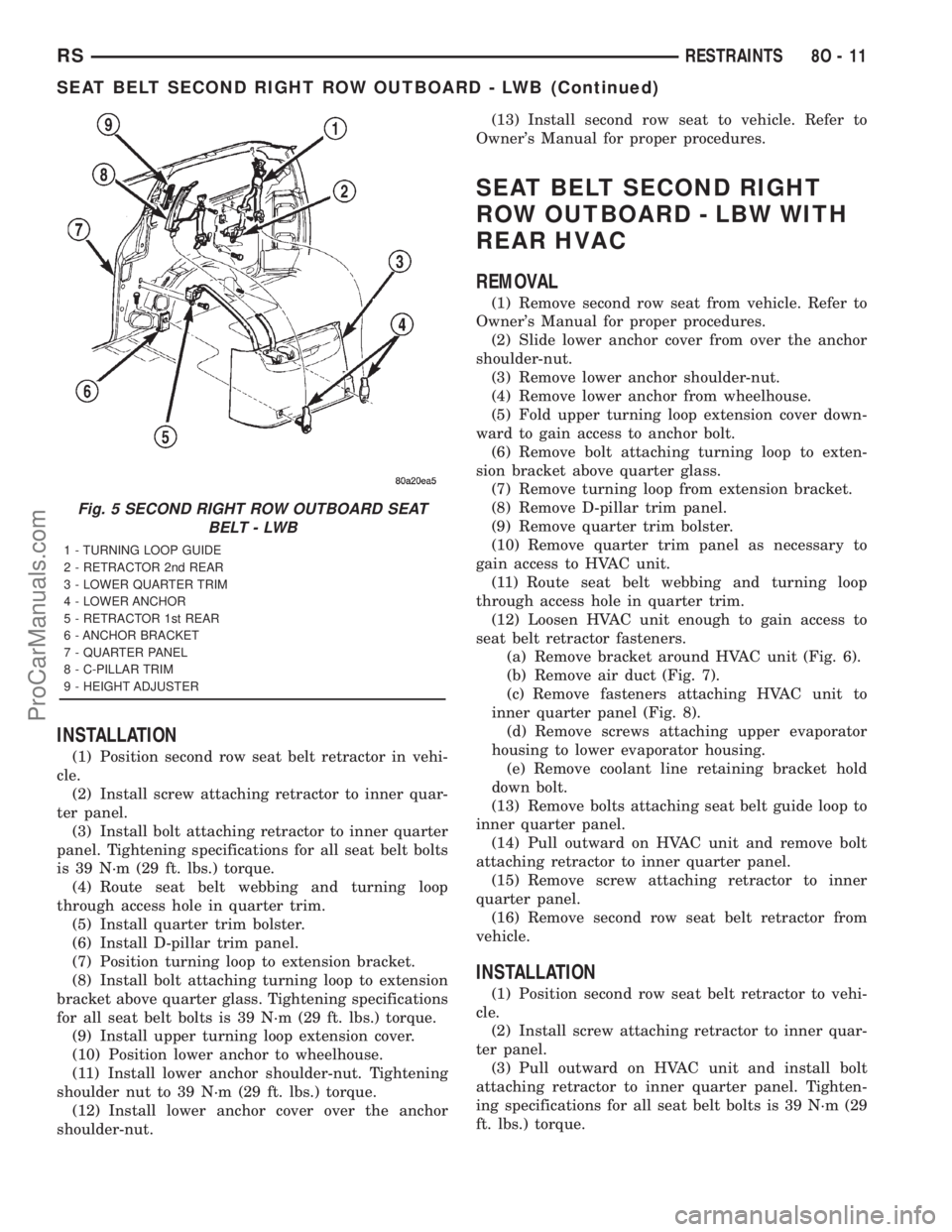
Fig. 5 SECOND RIGHT ROW OUTBOARD SEAT
BELT - LWB
1 - TURNING LOOP GUIDE
2 - RETRACTOR 2nd REAR
3 - LOWER QUARTER TRIM
4 - LOWER ANCHOR
5 - RETRACTOR 1st REAR
6 - ANCHOR BRACKET
7 - QUARTER PANEL
8 - C-PILLAR TRIM
9 - HEIGHT ADJUSTER
RSRESTRAINTS8O-11
SEAT BELT SECOND RIGHT ROW OUTBOARD - LWB (Continued)
ProCarManuals.com
Page 591 of 2321
(4) Install bolts attaching seat belt guide loop to
inner quarter panel.
(5) Install coolant line retaining bracket hold down
bolt.
(6) Install screws attaching upper evaporator
housing to lower evaporator housing.
(7) Install fasteners attaching HVAC unit to inner
quarter panel.
(8) Install air duct.
(9) Install bracket around HVAC unit.
(10) Route seat belt webbing and turning loop
through access hole in quarter trim.
(11) Install quarter trim panel as necessary to gain
access to HVAC unit.
(12) Install quarter trim bolster.
(13) Install D-pillar trim panel.
(14) Position turning loop to extension bracket.(15) Install bolt attaching turning loop to exten-
sion bracket above quarter glass. Tightening seat belt
bolt to 39 N´m (29 ft. lbs.) torque.
(16) Pull upper turning loop extension cover
upward over anchor bolt.
(17) Install lower anchor shoulder-nut. Tightening
seat belt bolt to 39 N´m (29 ft. lbs.) torque.
(18) Slide lower anchor cover over anchor shoul-
der-nut.
(19) Install second row seat from vehicle. Refer to
Owner's Manual for proper procedures.
SEAT BELT SECOND ROW
OUTBOARD - SWB
REMOVAL
(1) Remove second row seat from vehicle. Refer to
Owner's Manual for proper procedures.
(2) Slide lower anchor cover from over the anchor
shoulder-nut.
(3) Remove lower anchor shoulder-nut.
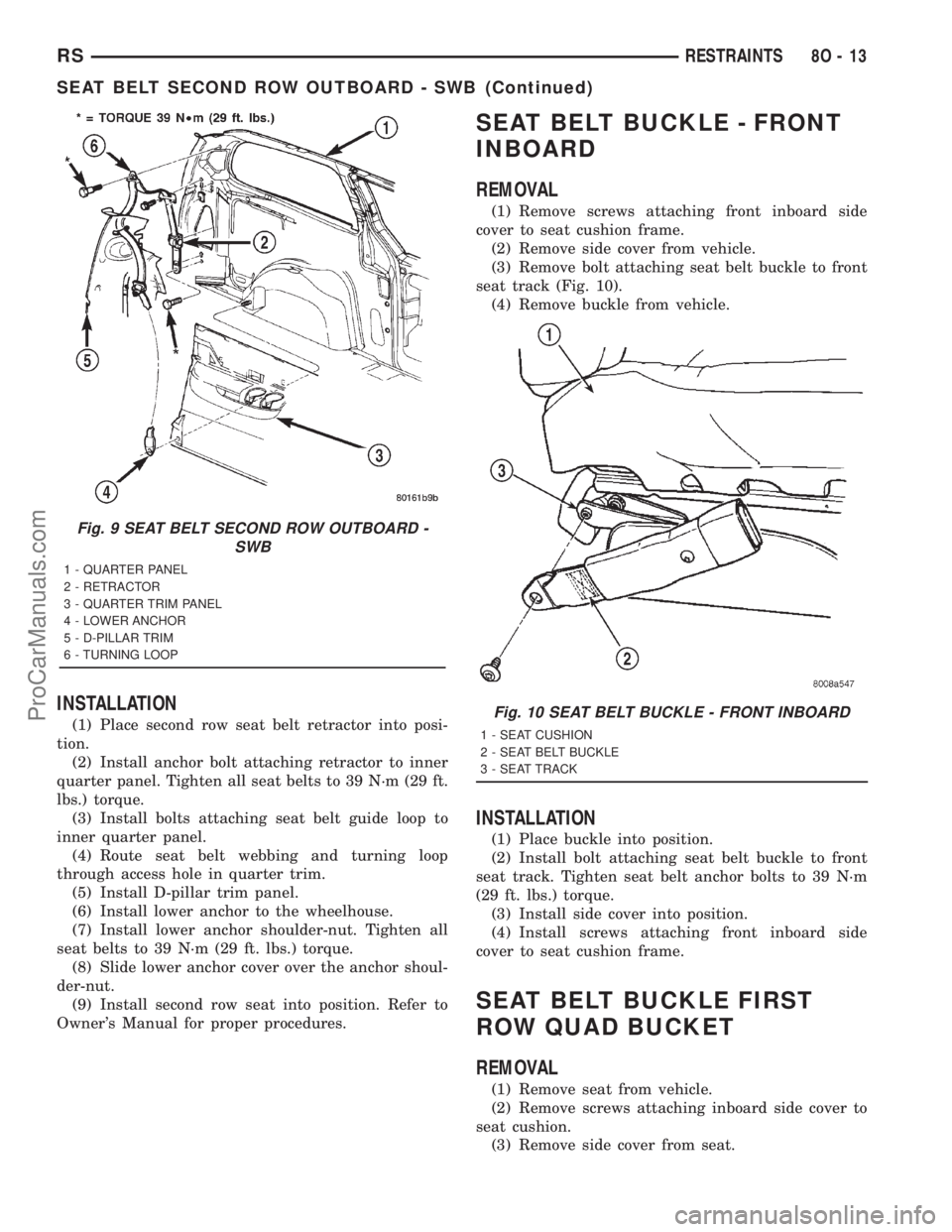
(4) Remove lower anchor from wheelhouse (Fig. 9).
(5) Remove D-pillar trim panel.
(6) Route seat belt webbing and turning loop
through access hole in quarter trim.
(7) Remove bolts attaching seat belt guide loop to
inner quarter panel.
(8) Remove anchor bolt attaching retractor to
inner quarter panel.
(9) Remove second row seat belt retractor from
vehicle (Fig. 9).
Fig. 6 TRIM PANEL MOUNTING BRACKET
1 - TRIM PANEL MOUNTING BRACKET
Fig. 7 LOWER HEATER DUCT
1 - LOWER HEAT DUCT MOUNTING
Fig. 8 REAR HVAC MOUNTING
1 - REAR HVAC MODULE MOUNTING
2 - REAR EVAPORATOR LOWER HOUSING
3 - REAR EVAPORATOR UPPER HOUSING
8O - 12 RESTRAINTSRS
SEAT BELT SECOND RIGHT ROW OUTBOARD - LBW WITH REAR HVAC (Continued)
ProCarManuals.com
Page 592 of 2321
INSTALLATION
(1) Place second row seat belt retractor into posi-
tion.
(2) Install anchor bolt attaching retractor to inner
quarter panel. Tighten all seat belts to 39 N´m (29 ft.
lbs.) torque.
(3) Install bolts attaching seat belt guide loop to
inner quarter panel.
(4) Route seat belt webbing and turning loop
through access hole in quarter trim.
(5) Install D-pillar trim panel.
(6) Install lower anchor to the wheelhouse.
(7) Install lower anchor shoulder-nut. Tighten all
seat belts to 39 N´m (29 ft. lbs.) torque.
(8) Slide lower anchor cover over the anchor shoul-
der-nut.
(9) Install second row seat into position. Refer to
Owner's Manual for proper procedures.
SEAT BELT BUCKLE - FRONT
INBOARD
REMOVAL
(1) Remove screws attaching front inboard side
cover to seat cushion frame.
(2) Remove side cover from vehicle.
(3) Remove bolt attaching seat belt buckle to front
seat track (Fig. 10).
(4) Remove buckle from vehicle.
INSTALLATION
(1) Place buckle into position.
(2) Install bolt attaching seat belt buckle to front
seat track. Tighten seat belt anchor bolts to 39 N´m
(29 ft. lbs.) torque.
(3) Install side cover into position.
(4) Install screws attaching front inboard side
cover to seat cushion frame.
SEAT BELT BUCKLE FIRST
ROW QUAD BUCKET
REMOVAL
(1) Remove seat from vehicle.
(2) Remove screws attaching inboard side cover to
seat cushion.
(3) Remove side cover from seat.
Fig. 9 SEAT BELT SECOND ROW OUTBOARD -
SWB
1 - QUARTER PANEL
2 - RETRACTOR
3 - QUARTER TRIM PANEL
4 - LOWER ANCHOR
5 - D-PILLAR TRIM
6 - TURNING LOOP
Fig. 10 SEAT BELT BUCKLE - FRONT INBOARD
1 - SEAT CUSHION
2 - SEAT BELT BUCKLE
3 - SEAT TRACK
RSRESTRAINTS8O-13
SEAT BELT SECOND ROW OUTBOARD - SWB (Continued)
ProCarManuals.com
Page 1204 of 2321
²Step 3: Final torque collar to transaxle bolts to
101 N´m (75 ft. lbs.)
²Step 4: Final torque collar to oil pan bolts to 54
N´m (40 ft. lbs.).
(2) Install engine front mount bracket and insula-
tor. (Refer to 9 - ENGINE/ENGINE MOUNTING/
FRONT MOUNT - INSTALLATION)
(3) Lower vehicle.
ENGINE MOUNTING
DESCRIPTION
The engine mounting system consist of four
mounts; right and a left side support the powertrain,
and a front and a rear mount control powertrain
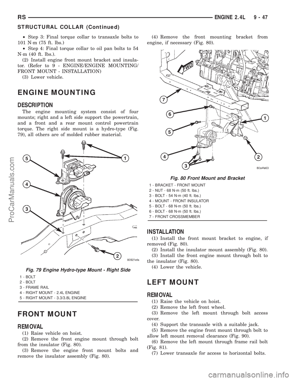
torque. The right side mount is a hydro-type (Fig.
79), all others are of molded rubber material.
FRONT MOUNT
REMOVAL
(1) Raise vehicle on hoist.
(2) Remove the front engine mount through bolt
from the insulator (Fig. 80).
(3) Remove the engine front mount bolts and
remove the insulator assembly (Fig. 80).(4) Remove the front mounting bracket from
engine, if necessary (Fig. 80).
INSTALLATION
(1) Install the front mount bracket to engine, if
removed (Fig. 80).
(2) Install the insulator mount assembly (Fig. 80).
(3) Install the front engine mount through bolt to
the insulator (Fig. 80).
(4) Lower the vehicle.
LEFT MOUNT
REMOVAL
(1) Raise the vehicle on hoist.
(2) Remove the left front wheel.
(3) Remove the left mount through bolt access
cover.
(4) Support the transaxle with a suitable jack.
(5) Remove the engine front mount through bolt to
allow left mount removal clearance (Fig. 90).
(6) Remove the left mount through frame rail bolt
(Fig. 81).
(7) Lower transaxle for access to horizontal bolts.
Fig. 79 Engine Hydro-type Mount - Right Side
1 - BOLT
2 - BOLT
3 - FRAME RAIL
4 - RIGHT MOUNT - 2.4L ENGINE
5 - RIGHT MOUNT - 3.3/3.8L ENGINE
Fig. 80 Front Mount and Bracket
1 - BRACKET - FRONT MOUNT
2 - NUT - 68 N´m (50 ft. lbs.)
3 - BOLT - 54 N´m (40 ft. lbs.)
4 - MOUNT - FRONT INSULATOR
5 - BOLT - 68 N´m (50 ft. lbs.)
6 - BOLT - 68 N´m (50 ft. lbs.)
7 - FRONT CROSSMEMBER
RSENGINE 2.4L9-47
STRUCTURAL COLLAR (Continued)
ProCarManuals.com
Page 1322 of 2321
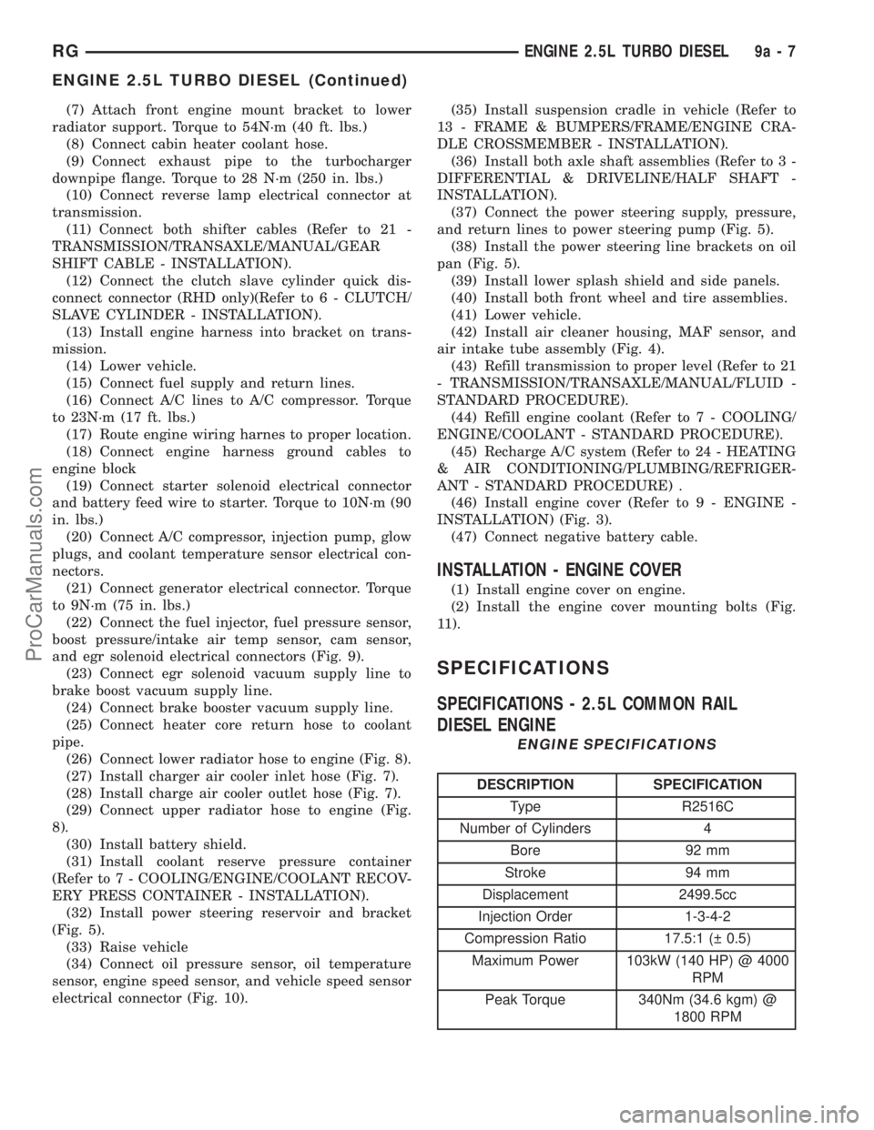
(7) Attach front engine mount bracket to lower
radiator support. Torque to 54N´m (40 ft. lbs.)
(8) Connect cabin heater coolant hose.
(9) Connect exhaust pipe to the turbocharger
downpipe flange. Torque to 28 N´m (250 in. lbs.)
(10) Connect reverse lamp electrical connector at
transmission.
(11) Connect both shifter cables (Refer to 21 -
TRANSMISSION/TRANSAXLE/MANUAL/GEAR
SHIFT CABLE - INSTALLATION).
(12) Connect the clutch slave cylinder quick dis-
connect connector (RHD only)(Refer to 6 - CLUTCH/
SLAVE CYLINDER - INSTALLATION).
(13) Install engine harness into bracket on trans-
mission.
(14) Lower vehicle.
(15) Connect fuel supply and return lines.
(16) Connect A/C lines to A/C compressor. Torque
to 23N´m (17 ft. lbs.)
(17) Route engine wiring harnes to proper location.
(18) Connect engine harness ground cables to
engine block
(19) Connect starter solenoid electrical connector
and battery feed wire to starter. Torque to 10N´m (90
in. lbs.)
(20) Connect A/C compressor, injection pump, glow
plugs, and coolant temperature sensor electrical con-
nectors.
(21) Connect generator electrical connector. Torque
to 9N´m (75 in. lbs.)
(22) Connect the fuel injector, fuel pressure sensor,
boost pressure/intake air temp sensor, cam sensor,
and egr solenoid electrical connectors (Fig. 9).
(23) Connect egr solenoid vacuum supply line to
brake boost vacuum supply line.
(24) Connect brake booster vacuum supply line.
(25) Connect heater core return hose to coolant
pipe.
(26) Connect lower radiator hose to engine (Fig. 8).
(27) Install charger air cooler inlet hose (Fig. 7).
(28) Install charge air cooler outlet hose (Fig. 7).
(29) Connect upper radiator hose to engine (Fig.
8).
(30) Install battery shield.
(31) Install coolant reserve pressure container
(Refer to 7 - COOLING/ENGINE/COOLANT RECOV-
ERY PRESS CONTAINER - INSTALLATION).
(32) Install power steering reservoir and bracket
(Fig. 5).
(33) Raise vehicle
(34) Connect oil pressure sensor, oil temperature
sensor, engine speed sensor, and vehicle speed sensor
electrical connector (Fig. 10).(35) Install suspension cradle in vehicle (Refer to
13 - FRAME & BUMPERS/FRAME/ENGINE CRA-
DLE CROSSMEMBER - INSTALLATION).
(36) Install both axle shaft assemblies (Refer to 3 -
DIFFERENTIAL & DRIVELINE/HALF SHAFT -
INSTALLATION).
(37) Connect the power steering supply, pressure,
and return lines to power steering pump (Fig. 5).
(38) Install the power steering line brackets on oil
pan (Fig. 5).
(39) Install lower splash shield and side panels.
(40) Install both front wheel and tire assemblies.
(41) Lower vehicle.
(42) Install air cleaner housing, MAF sensor, and
air intake tube assembly (Fig. 4).
(43) Refill transmission to proper level (Refer to 21
- TRANSMISSION/TRANSAXLE/MANUAL/FLUID -
STANDARD PROCEDURE).
(44) Refill engine coolant (Refer to 7 - COOLING/
ENGINE/COOLANT - STANDARD PROCEDURE).
(45) Recharge A/C system (Refer to 24 - HEATING
& AIR CONDITIONING/PLUMBING/REFRIGER-
ANT - STANDARD PROCEDURE) .
(46) Install engine cover (Refer to 9 - ENGINE -
INSTALLATION) (Fig. 3).
(47) Connect negative battery cable.
INSTALLATION - ENGINE COVER
(1) Install engine cover on engine.
(2) Install the engine cover mounting bolts (Fig.
11).
SPECIFICATIONS
SPECIFICATIONS - 2.5L COMMON RAIL
DIESEL ENGINE
ENGINE SPECIFICATIONS
DESCRIPTION SPECIFICATION
Type R2516C
Number of Cylinders 4
Bore 92 mm
Stroke 94 mm
Displacement 2499.5cc
Injection Order 1-3-4-2
Compression Ratio 17.5:1 ( 0.5)
Maximum Power 103kW (140 HP) @ 4000
RPM
Peak Torque 340Nm (34.6 kgm) @
1800 RPM
RGENGINE 2.5L TURBO DIESEL9a-7
ENGINE 2.5L TURBO DIESEL (Continued)
ProCarManuals.com
Page 1325 of 2321
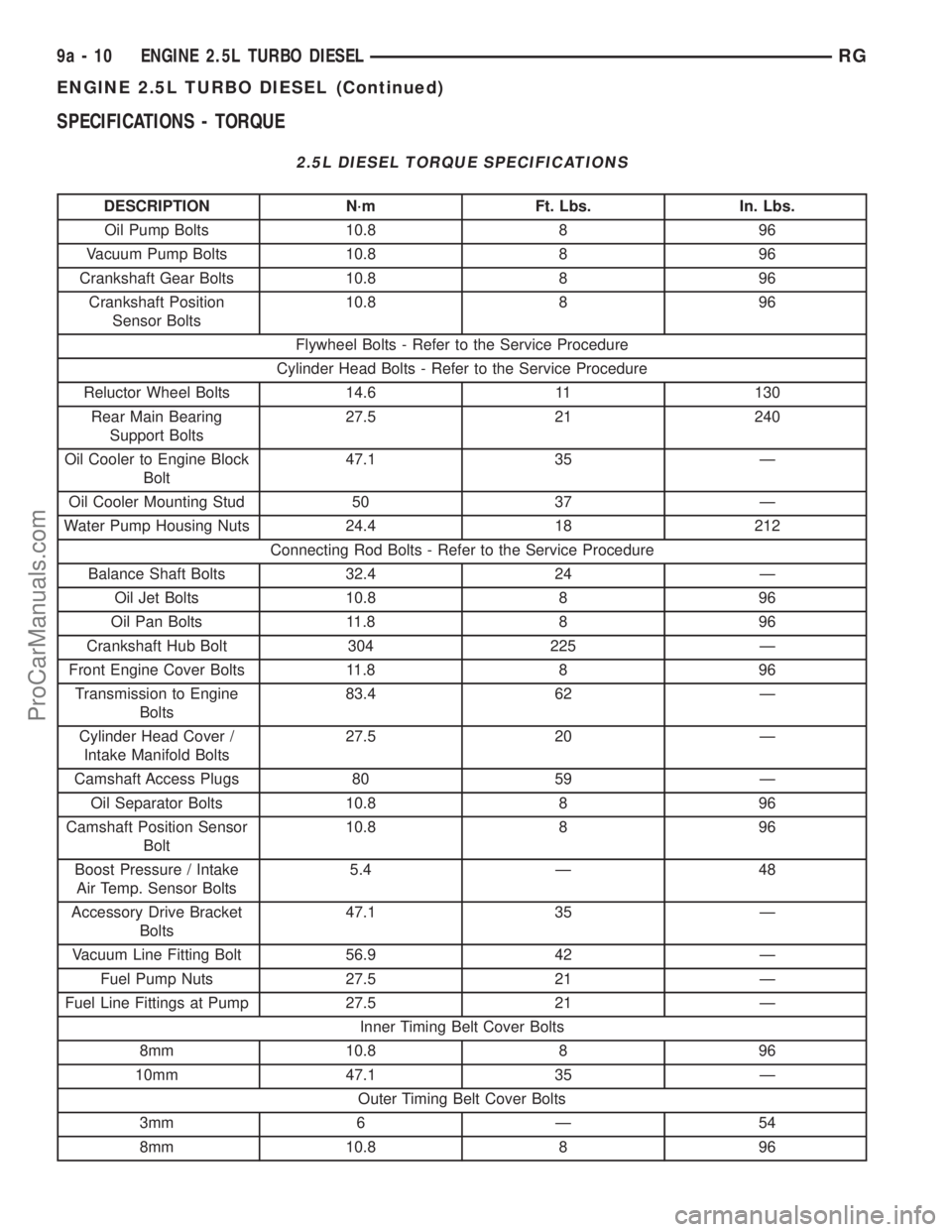
SPECIFICATIONS - TORQUE
2.5L DIESEL TORQUE SPECIFICATIONS
DESCRIPTION N´m Ft. Lbs. In. Lbs.
Oil Pump Bolts 10.8 8 96
Vacuum Pump Bolts 10.8 8 96
Crankshaft Gear Bolts 10.8 8 96
Crankshaft Position
Sensor Bolts10.8 8 96
Flywheel Bolts - Refer to the Service Procedure
Cylinder Head Bolts - Refer to the Service Procedure
Reluctor Wheel Bolts 14.6 11 130
Rear Main Bearing
Support Bolts27.5 21 240
Oil Cooler to Engine Block
Bolt47.1 35 Ð
Oil Cooler Mounting Stud 50 37 Ð
Water Pump Housing Nuts 24.4 18 212
Connecting Rod Bolts - Refer to the Service Procedure
Balance Shaft Bolts 32.4 24 Ð
Oil Jet Bolts 10.8 8 96
Oil Pan Bolts 11.8 8 96
Crankshaft Hub Bolt 304 225 Ð
Front Engine Cover Bolts 11.8 8 96
Transmission to Engine
Bolts83.4 62 Ð
Cylinder Head Cover /
Intake Manifold Bolts27.5 20 Ð
Camshaft Access Plugs 80 59 Ð
Oil Separator Bolts 10.8 8 96
Camshaft Position Sensor
Bolt10.8 8 96
Boost Pressure / Intake
Air Temp. Sensor Bolts5.4 Ð 48
Accessory Drive Bracket
Bolts47.1 35 Ð
Vacuum Line Fitting Bolt 56.9 42 Ð
Fuel Pump Nuts 27.5 21 Ð
Fuel Line Fittings at Pump 27.5 21 Ð
Inner Timing Belt Cover Bolts
8mm 10.8 8 96
10mm 47.1 35 Ð
Outer Timing Belt Cover Bolts
3mm 6 Ð 54
8mm 10.8 8 96
9a - 10 ENGINE 2.5L TURBO DIESELRG
ENGINE 2.5L TURBO DIESEL (Continued)
ProCarManuals.com
Page 1349 of 2321
(5) Install front engine cover (Refer to 9 -
ENGINE/ENGINE BLOCK/ENGINE COVER -
INSTALLATION).
(6) Install rear main bearing support in engine
block.Be sure to align oil hole in rear main
bearing support with hole in block.
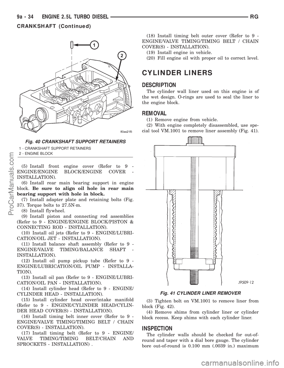
(7) Install adapter plate and retaining bolts (Fig.
37). Torque bolts to 27.5N´m.
(8) Install flywheel.
(9) Install piston and connecting rod assemblies
(Refer to 9 - ENGINE/ENGINE BLOCK/PISTON &
CONNECTING ROD - INSTALLATION).
(10) Install oil jets (Refer to 9 - ENGINE/LUBRI-
CATION/OIL JET - INSTALLATION).
(11) Install balance shaft assembly (Refer to 9 -
ENGINE/VALVE TIMING/BALANCE SHAFT -
INSTALLATION).
(12) Install oil pump pickup tube (Refer to 9 -
ENGINE/LUBRICATION/OIL PUMP - INSTALLA-
TION).
(13) Install oil pan (Refer to 9 - ENGINE/LUBRI-
CATION/OIL PAN - INSTALLATION).
(14) Install cylinder head (Refer to 9 - ENGINE/
CYLINDER HEAD - INSTALLATION).
(15) Install cylinder head cover/intake manifold
(Refer to 9 - ENGINE/CYLINDER HEAD/CYLIN-
DER HEAD COVER(S) - INSTALLATION).
(16) Install timing belt inner cover (Refer to 9 -
ENGINE/VALVE TIMING/TIMING BELT / CHAIN
COVER(S) - INSTALLATION).
(17) Install timing belt (Refer to 9 - ENGINE/
VALVE TIMING/TIMING BELT/CHAIN AND
SPROCKETS - INSTALLATION) .(18) Install timing belt outer cover (Refer to 9 -
ENGINE/VALVE TIMING/TIMING BELT / CHAIN
COVER(S) - INSTALLATION).
(19) Install engine in vehicle.
(20) Fill engine oil with proper oil to correct level.
CYLINDER LINERS
DESCRIPTION
The cylinder wall liner used on this engine is of
the wet design. O-rings are used to seal the liner to
the engine block.
REMOVAL
(1) Remove engine from vehicle.
(2) With engine completely disassembled, use spe-
cial tool VM.1001 to remove liner assembly (Fig. 41).
(3) Tighten bolt on VM.1001 to remove liner from
block (Fig. 42).
(4) Remove shims from cylinder liner or cylinder
block recess. Keep shims with each cylinder liner.
INSPECTION
The cylinder walls should be checked for out-of-
round and taper with a dial bore gauge. The cylinder
bore out-of-round is 0.100 mm (.0039 in.) maximum
Fig. 40 CRANKSHAFT SUPPORT RETAINERS
1 - CRANKSHAFT SUPPORT RETAINERS
2 - ENGINE BLOCK
Fig. 41 CYLINDER LINER REMOVER
9a - 34 ENGINE 2.5L TURBO DIESELRG
CRANKSHAFT (Continued)
ProCarManuals.com
Page 1361 of 2321
INSTALLATION
CRANKSHAFT MAIN BEARINGS
(1) Install bearing halves in crankshaft supports.
(2) Lubricate crankshaft and main bearings with
clean engine oil.
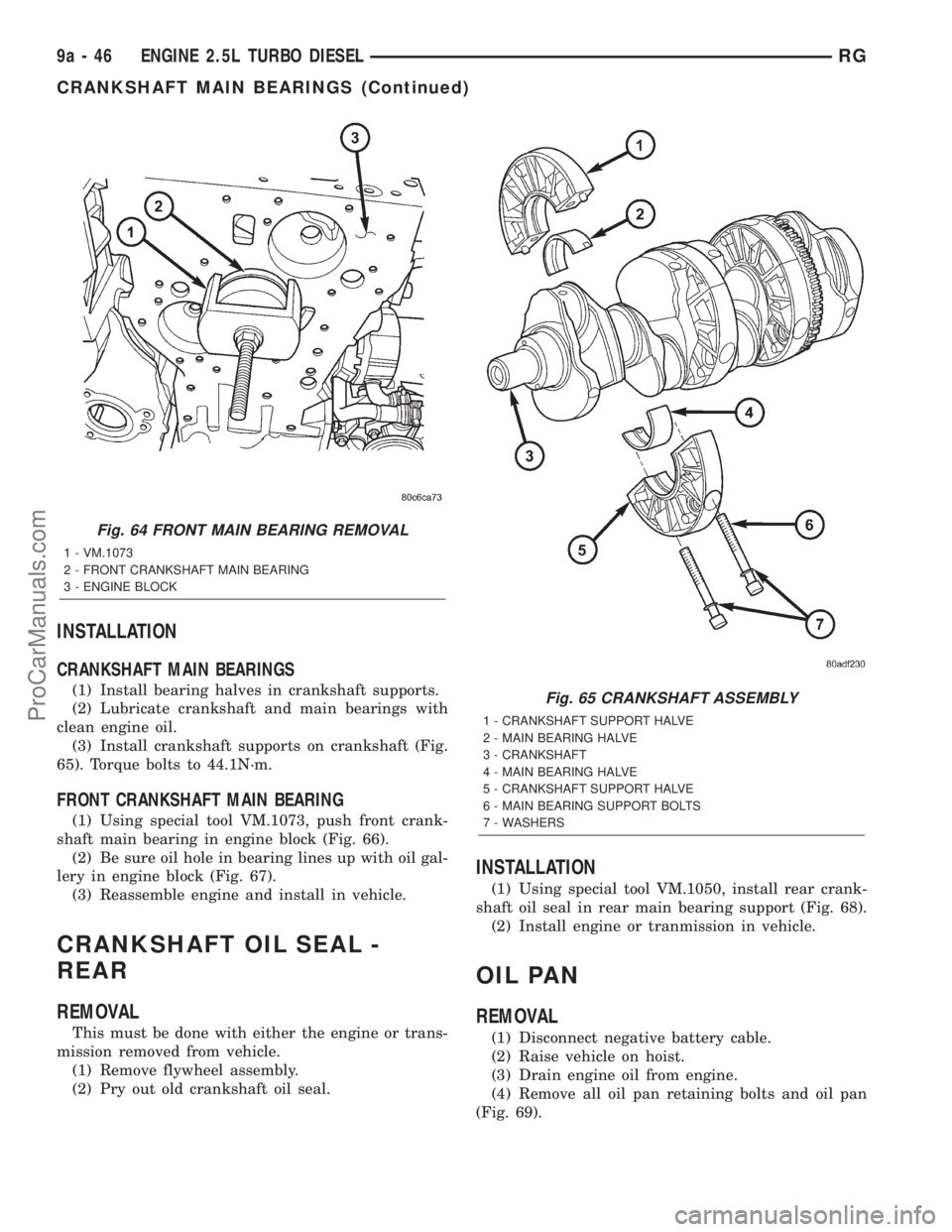
(3) Install crankshaft supports on crankshaft (Fig.
65). Torque bolts to 44.1N´m.
FRONT CRANKSHAFT MAIN BEARING
(1) Using special tool VM.1073, push front crank-
shaft main bearing in engine block (Fig. 66).
(2) Be sure oil hole in bearing lines up with oil gal-
lery in engine block (Fig. 67).
(3) Reassemble engine and install in vehicle.
CRANKSHAFT OIL SEAL -
REAR
REMOVAL
This must be done with either the engine or trans-
mission removed from vehicle.
(1) Remove flywheel assembly.
(2) Pry out old crankshaft oil seal.
INSTALLATION
(1) Using special tool VM.1050, install rear crank-
shaft oil seal in rear main bearing support (Fig. 68).
(2) Install engine or tranmission in vehicle.
OIL PAN
REMOVAL
(1) Disconnect negative battery cable.
(2) Raise vehicle on hoist.
(3) Drain engine oil from engine.
(4) Remove all oil pan retaining bolts and oil pan
(Fig. 69).
Fig. 64 FRONT MAIN BEARING REMOVAL
1 - VM.1073
2 - FRONT CRANKSHAFT MAIN BEARING
3 - ENGINE BLOCK
Fig. 65 CRANKSHAFT ASSEMBLY
1 - CRANKSHAFT SUPPORT HALVE
2 - MAIN BEARING HALVE
3 - CRANKSHAFT
4 - MAIN BEARING HALVE
5 - CRANKSHAFT SUPPORT HALVE
6 - MAIN BEARING SUPPORT BOLTS
7 - WASHERS
9a - 46 ENGINE 2.5L TURBO DIESELRG
CRANKSHAFT MAIN BEARINGS (Continued)
ProCarManuals.com