2001 DODGE TOWN AND COUNTRY oil pressure
[x] Cancel search: oil pressurePage 377 of 2321
PCM determines basic fuel injector pulse width from
this input.
²The PCM determines atmospheric air pressure
from the MAP sensor input to modify injector pulse
width.
When the key is in the ON position and the engine
is not running (zero rpm), the Auto Shutdown (ASD)
and fuel pump relays de-energize after approximately
1 second. Therefore, battery voltage is not supplied to
the fuel pump, ignition coil, fuel injectors and heated
oxygen sensors.
ENGINE START-UP MODE
This is an OPEN LOOP mode. If the vehicle is in
park or neutral (automatic transaxles) or the clutch
pedal is depressed (manual transaxles) the ignition
switch energizes the starter relay. The following
actions occur when the starter motor is engaged.
²If the PCM receives the camshaft position sensor
and crankshaft position sensor signals, it energizes
the Auto Shutdown (ASD) relay and fuel pump relay.
If the PCM does not receive both signals within
approximately one second, it will not energize the
ASD relay and fuel pump relay. The ASD and fuel
pump relays supply battery voltage to the fuel pump,
fuel injectors, ignition coil and heated oxygen sen-
sors.
²The PCM energizes the injectors (on the 69É
degree falling edge) for a calculated pulse width until
it determines crankshaft position from the camshaft
position sensor and crankshaft position sensor sig-
nals. The PCM determines crankshaft position within
1 engine revolution.
²After determining crankshaft position, the PCM
begins energizing the injectors in sequence. It adjusts
injector pulse width and controls injector synchroni-
zation by turning the individual ground paths to the
injectors On and Off.
²When the engine idles within664 RPM of its
target RPM, the PCM compares current MAP sensor
value with the atmospheric pressure value received
during the Ignition Switch On (zero RPM) mode.
Once the ASD and fuel pump relays have been
energized, the PCM determines injector pulse width
based on the following:
²Battery voltage
²Engine coolant temperature
²Engine RPM
²Inlet/Intake air temperature (IAT)
²MAP
²Throttle position
²The number of engine revolutions since cranking
was initiated
During Start-up the PCM maintains ignition tim-
ing at 9É BTDC.
ENGINE WARM-UP MODE
This is an OPEN LOOP mode. The following inputs
are received by the PCM:
²Engine coolant temperature
²Manifold Absolute Pressure (MAP)
²Inlet/Intake air temperature (IAT)
²Crankshaft position (engine speed)
²Camshaft position
²Knock sensor
²Throttle position
²A/C switch
²Battery voltage
²Vehicle speed
²Speed control
²O2 sensors
The PCM adjusts injector pulse width and controls
injector synchronization by turning the individual
ground paths to the injectors On and Off.
The PCM adjusts ignition timing and engine idle
speed. Engine idle speed is adjusted through the idle
air control motor.
CRUISE OR IDLE MODE
When the engine is at operating temperature this
is a CLOSED LOOP mode. During cruising or idle
the following inputs are received by the PCM:
²Inlet/Intake air temperature
²Engine coolant temperature
²Manifold absolute pressure
²Crankshaft position (engine speed)
²Camshaft position
²Knock sensor
²Throttle position
²Exhaust gas oxygen content
²A/C control positions
²Battery voltage
²Vehicle speed
The PCM adjusts injector pulse width and controls
injector synchronization by turning the individual
ground paths to the injectors On and Off.
The PCM adjusts engine idle speed and ignition
timing. The PCM adjusts the air/fuel ratio according
to the oxygen content in the exhaust gas (measured
by the upstream and downstream heated oxygen sen-
sor).
The PCM monitors for engine misfire. During
active misfire and depending on the severity, the
PCM either continuously illuminates or flashes the
malfunction indicator lamp (Check Engine light on
instrument panel). Also, the PCM stores an engine
misfire DTC in memory.
The PCM performs several diagnostic routines.
They include:
²Oxygen sensor monitor
²Downstream heated oxygen sensor diagnostics
during open loop operation (except for shorted)
8E - 20 ELECTRONIC CONTROL MODULESRS
POWERTRAIN CONTROL MODULE (Continued)
ProCarManuals.com
Page 384 of 2321

Schedule Condition Expected Operation
HotOil temperature at start-up above
80É F± Normal operation (upshift,
kickdowns, and coastdowns)
± Full EMCC, no PEMCC except to
engage FEMCC (except at closed
throttle at speeds above 70-83 mph)
OverheatOil temperature above 240É F or
engine coolant temperature above
244É F± Delayed 2-3 upshift (25-32 mph)
± Delayed 3-4 upshift (41-48 mph)
± 3rd gear FEMCC from 30-48 mph
± 3rd gear PEMCC from 27-31 mph
Super OverheatOil temperature above 260É F ± All9Overheat9shift schedule
features apply
± 2nd gear PEMCC above 22 mph
± Above 22 mph the torque
converter will not unlock unless the
throttle is closed or if a wide open
throttle 2nd PEMCC to 1 kickdown
is made
STANDARD PROCEDURE - PINION FACTOR
SETTING
NOTE: This procedure must be performed if the
Transmission Control Module (TCM) has been
replaced with a NEW or replacement unit. Failure to
perform this procedure will result in an inoperative
or improperly calibrated speedometer.
The vehicle speed readings for the speedometer are
taken from the output speed sensor. The TCM must
be calibrated to the different combinations of equip-
ment (final drive and tires) available. Pinion Factor
allows the technician to set the Transmission Control
Module initial setting so that the speedometer read-
ings will be correct. To properly read and/or reset the
Pinion Factor, it is necessary to use a DRB scan tool.
(1) Plug the DRB scan tool into the diagnostic con-
nector located under the instrument panel.
(2) Select the Transmission menu.
(3) Select the Miscellaneous menu.
(4) Select Pinion Factor. Then follow the instruc-
tions on the DRB scan tool screen.
STANDARD PROCEDURE - QUICK LEARN
PROCEDURE
The quick learn procedure requires the use of the
DRB scan tool. This program allows the electronic
transaxle system to recalibrate itself. This will pro-
vide the best possible transaxle operation.NOTE: The quick learn procedure should be per-
formed if any of the following procedures are per-
formed:
²Transaxle Assembly Replacement
²Transmission Control Module Replacement
²Solenoid/Pressure Switch Assembly Replacement
²Clutch Plate and/or Seal Replacement
²Valve Body Replacement or Recondition
To perform the Quick Learn Procedure, the follow-
ing conditions must be met:
²The brakes must be applied
²The engine speed must be above 500 rpm
²The throttle angle (TPS) must be less than 3
degrees
²The shift lever position must stay until
prompted to shift to overdrive
²The shift lever position must stay in overdrive
after the Shift to Overdrive prompt until the DRB
indicates the procedure is complete
²The calculated oil temperature must be above
60É and below 200É
(1) Plug the DRB scan tool into the diagnostic con-
nector. The connector is located under the instrument
panel.
(2) Go to the Transmission screen.
(3) Go to the Miscellaneous screen.
(4) Select Quick Learn Procedure. Follow the
instructions of the DRB to perform the Quick Learn
Procedure.
RSELECTRONIC CONTROL MODULES8E-27
TRANSMISSION CONTROL MODULE (Continued)
ProCarManuals.com
Page 408 of 2321

CHARGING
TABLE OF CONTENTS
page page
CHARGING
DESCRIPTION...........................21
OPERATION.............................21
DIAGNOSIS AND TESTING.................22
ON-BOARD DIAGNOSTIC SYSTEM.........22
SPECIFICATIONS........................22
SPECIAL TOOLS.........................23
BATTERY TEMPERATURE SENSOR
DESCRIPTION...........................23
OPERATION.............................23
REMOVAL..............................23
GENERATOR
DESCRIPTION...........................23
OPERATION.............................23REMOVAL..............................23
INSTALLATION...........................24
GENERATOR DECOUPLER PULLEY
DESCRIPTION...........................25
OPERATION.............................25
DIAGNOSIS AND TESTING.................25
GENERATOR DECOUPLER...............25
REMOVAL..............................25
INSTALLATION...........................26
VOLTAGE REGULATOR
DESCRIPTION...........................26
OPERATION.............................26
REMOVAL..............................26
CHARGING
DESCRIPTION - CHARGING SYSTEM
The charging system consists of:
²Generator
²Decoupler Pulley (If equipped)
²Electronic Voltage Regulator (EVR) circuitry
within the Powertrain Control Module (PCM)
²Ignition switch (refer to the Ignition System sec-
tion for information)
²Battery (refer to the Battery section for informa-
tion)
²Battery temperature sensor
²Voltmeter (refer to the Instrument Cluster sec-
tion for information)
²Wiring harness and connections (refer to the
Wiring section for information)
²Accessory drive belt (refer to the Cooling section
for more information)
OPERATION - CHARGING SYSTEM
The charging system is turned on and off with the
ignition switch. The system is on when the engine is
running and the ASD relay is energized. When the
ASD relay is on, voltage is supplied to the ASD relay
sense circuit at the PCM. This voltage is connected
through the PCM and supplied to one of the genera-
tor field terminals (Gen. Source +) at the back of the
generator.
The generator is driven by the engine through a
serpentine belt and pulley or decoupler pulley
arrangement.The amount of DC current produced by the gener-
ator is controlled by the EVR (field control) circuitry
contained within the PCM. This circuitry is con-
nected in series with the second rotor field terminal
and ground.
A battery temperature sensor is used to sense bat-
tery temperature. This temperature data, along with
data from monitored line voltage, is used by the PCM
to vary the battery charging rate. This is done by
cycling the ground path to control the strength of the
rotor magnetic field. The PCM then compensates and
regulates generator current output accordingly to
maintain system voltage at the targeted system volt-
age based on battery temperature.
All vehicles are equipped with On-Board Diagnos-
tics (OBD). All OBD-sensed systems, including EVR
(field control) circuitry, are monitored by the PCM.
Each monitored circuit is assigned a Diagnostic Trou-
ble Code (DTC). The PCM will store a DTC in elec-
tronic memory for certain failures it detects. Refer to
On-Board Diagnostics in the Electronic Control Mod-
ules(Refer to 8 - ELECTRICAL/ELECTRONIC CON-
TROL MODULES/POWERTRAIN CONTROL
MODULE - DESCRIPTION) section for more DTC
information.
The Check Gauges Lamp (if equipped) monitors:
charging system voltage,engine coolant tempera-
ture and engine oil pressure. If an extreme condition
is indicated, the lamp will be illuminated. This is
done as reminder to check the three gauges. The sig-
nal to activate the lamp is sent via the PCI bus cir-
cuits. The lamp is located on the instrument panel.
Refer to the Instrument Cluster section for additional
information.
RSCHARGING8F-21
ProCarManuals.com
Page 423 of 2321
Spiral plate technology is the process by which the
plates holding the active material in the battery are
wound tightly in coils instead of hanging flat, like
conventional batteries. This design has a lower inter-
nal resistance and also increases the active material
surface area.
WARNING: NEVER EXCEED 14.4 VOLTS WHEN
CHARGING A SPIRAL PLATE BATTERY. PERSONAL
INJURY AND/OR BATTERY DAMAGE MAY RESULT.
Due to the maintanance-free design, distilled water
cannot be added to this battery. Therefore, if more
than 14.4 volts are used during the spiral plate bat-
tery charging process, water vapor can be exhausted
through the pressure-sensitive battery vents and lost
for good. This can permanently damage the spiral
plate battery. Never exceed 14.4 volts when charging
a spiral plate battery. Personal injury and/or battery
damage may result.
CONVENTIONAL BATTERY - GASOLINE ENGINE
Low-maintenance conventional batteries are used
on vehicles equipped with a gasoline engine, these
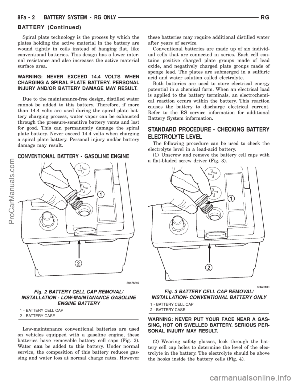
batteries have removable battery cell caps (Fig. 2).
Watercanbe added to this battery. Under normal
service, the composition of this battery reduces gas-
sing and water loss at normal charge rates. Howeverthese batteries may require additional distilled water
after years of service.
Conventional batteries are made up of six individ-
ual cells that are connected in series. Each cell con-
tains positive charged plate groups made of lead
oxide, and negatively charged plate groups made of
sponge lead. The plates are submerged in a sulfuric
acid and water solution called electrolyte.
Both batteries are used to store electrical energy
potential in a chemical form. When an electrical load
is applied to the battery terminals, an electrochemi-
cal reaction occurs within the battery. This reaction
causes the battery to discharge electrical current.
Refer to the RS service information for additional
Battery System information.
STANDARD PROCEDURE - CHECKING BATTERY
ELECTROLYTE LEVEL
The following procedure can be used to check the
electrolyte level in a lead-acid battery.
(1) Unscrew and remove the battery cell caps with
a flat-bladed screw driver (Fig. 3).
WARNING: NEVER PUT YOUR FACE NEAR A GAS-
SING, HOT OR SWELLED BATTERY. SERIOUS PER-
SONAL INJURY MAY RESULT.
(2) Wearing safety glasses, look through the bat-
tery cell cap holes to determine the level of the elec-
trolyte in the battery. The electrolyte should be above
the hooks inside the battery cells (Fig. 4).
Fig. 2 BATTERY CELL CAP REMOVAL/
INSTALLATION - LOW-MAINTANANCE GASOLINE
ENGINE BATTERY
1 - BATTERY CELL CAP
2 - BATTERY CASE
Fig. 3 BATTERY CELL CAP REMOVAL/
INSTALLATION- CONVENTIONAL BATTERY ONLY
1 - BATTERY CELL CAP
2 - BATTERY CASE
8Fa - 2 BATTERY SYSTEM - RG ONLYRG
BATTERY (Continued)
ProCarManuals.com
Page 632 of 2321
8W-02 COMPONENT INDEX
Component Page
A/C Compressor Clutch Relay........... 8Wa-42
A/C Compressor Clutch................ 8Wa-42
A/C-Heater Control................... 8Wa-42
A/C Pressure Sensor.................. 8Wa-42
Accelerator Pedal Position Sensor........ 8Wa-30
Accessory Relay...................... 8Wa-10
Airbags............................. 8Wa-43
Ambient Temp Sensor................. 8Wa-49
Antenna............................ 8Wa-47
ATC Remote Sensor................... 8Wa-42
Auto Shut Down Relay................. 8Wa-30
Auto Temp Control.................... 8Wa-42
Automatic Day/Night Mirror............ 8Wa-49
Autostick Switch..................... 8Wa-31
Back-Up Lamp Switch................. 8Wa-51
Battery Temperature Sensor............ 8Wa-20
Battery............................. 8Wa-20
Blend Door Actuators.................. 8Wa-42
Blower Motor Resistor................. 8Wa-42
Body Control Module.................. 8Wa-45
Boost Pressure Sensor................. 8Wa-30
B-Pillar Switches..................... 8Wa-61
Brake Fluid Level Switch............... 8Wa-40
Brake Lamp Switch................... 8Wa-51
Brake Transmission Shift Interlock
Solenoid.......................... 8Wa-31
Cabin Heater Assist................... 8Wa-30
Camshaft Position Sensor.............. 8Wa-30
CD Changer......................... 8Wa-47
Center High Mounted Stop Lamp........ 8Wa-51
Cinch/Release Motors.................. 8Wa-61
Clockspring................. 8Wa-33, 41, 43, 47
Clutch Pedal Interlock Switch Jumper..... 8Wa-10
Clutch Pedal Interlock Switch........... 8Wa-10
Clutch Pedal Upstop Switch............. 8Wa-30
Combination Relays................... 8Wa-54
Controller Antilock Brake.............. 8Wa-35
Crank Case Ventilation Heater.......... 8Wa-30
Crankshaft Position Sensor............. 8Wa-30
Cylinder Lock Switches................ 8Wa-39
Data Link Connector.................. 8Wa-18
Defogger Relay....................... 8Wa-48
Diagnostic Junction Port............... 8Wa-18
Dome Lamps........................ 8Wa-44
Door Ajar Switches.................... 8Wa-39
Door Courtesy Lamps.................. 8Wa-44
Door Lock Motor/Ajar Switches.......... 8Wa-61
Door Lock Switches................... 8Wa-61
Dosing Pump........................ 8Wa-30
Driver Heated Seat Module............. 8Wa-63
ECM/PCM Relay..................... 8Wa-30
EGR Solenoid........................ 8Wa-30Component Page
Electric Wiper De-Icer................. 8Wa-48
Engine Control Module................ 8Wa-30
Engine Coolant Temp Sensor............ 8Wa-30
Engine Oil Pressure Sensor............. 8Wa-30
Engine Oil Pressure Switch............. 8Wa-30
Engine Oil Temperature Sensor.......... 8Wa-30
EVAP/Purge Solenoid.................. 8Wa-30
Evaporator Temperature Sensor......... 8Wa-42
Floor Console Lamp................... 8Wa-44
Floor Console Power Outlet............. 8Wa-41
Fog Lamps.......................... 8Wa-50
Front Blower Module.................. 8Wa-42
Front Blower Motor Relay.............. 8Wa-42
Front Blower Motor................... 8Wa-42
Front Cigar Lighter................... 8Wa-41
Front Control Module.................. 8Wa-10
Front Fog Lamp Relay................. 8Wa-50
Front Intrusion Sensor................. 8Wa-39
Front Reading Lamps/Switch............ 8Wa-44
Front Washer Pump Motor.............. 8Wa-53
Front Wiper Hi/Low Relay.............. 8Wa-53
Front Wiper On/Off Relay.............. 8Wa-53
Fuel Heater Relay.................... 8Wa-10
Fuel Heater......................... 8Wa-30
Fuel Injectors........................ 8Wa-30
Fuel Pressure Sensor.................. 8Wa-30
Fuel Pressure Solenoid................. 8Wa-30
Fuel Pump Module.................... 8Wa-30
Fuel Pump Relay..................... 8Wa-30
Full Open Switches................... 8Wa-61
Fuselink............................ 8Wa-10
Fuses (IPM)......................... 8Wa-10
Generator........................... 8Wa-20
Glove Box Lamp...................... 8Wa-44
Glow Plug Relay...................... 8Wa-30
Glow Plugs.......................... 8Wa-30
Grounds............................ 8Wa-15
Halo Lamp.......................... 8Wa-44
Headlamp Leveling Motors............. 8Wa-50
Headlamp Switch..................... 8Wa-50
Headlamp Washer Pump Motor.......... 8Wa-53
Headlamp Washer Relay............... 8Wa-53
Headlamps.......................... 8Wa-50
Heated Seat Backs.................... 8Wa-63
Heated Seat Cushions................. 8Wa-63
High Beam Lamps.................... 8Wa-50
Hood Ajar Switch..................... 8Wa-39
Horn Relay.......................... 8Wa-41
Horn Switch......................... 8Wa-41
Horns.............................. 8Wa-41
Idle Air Control Motor................. 8Wa-30
Ignition Coil......................... 8Wa-30
RG8W-02 COMPONENT INDEX8Wa-02-1
ProCarManuals.com
Page 636 of 2321
8W-10 POWER DISTRIBUTION
Component PageA/C Compressor Clutch..................8Wa-10-19, 20, 38, 40
A/C Compressor Clutch Relay.............8Wa-10-19, 20, 37, 38, 40
Accessory Relay.......................8Wa-10-15, 26, 57
Ambient Temp Sensor........................8Wa-10-54
Auto Shut Down Relay......................8Wa-10-19, 34
Auto Temp Control.........................8Wa-10-33
Back-Up Lamp Switch........................8Wa-10-58
Battery........................8Wa-10-12, 13, 14, 34, 40
Blower Motor Resistor......................8Wa-10-17, 31
Body Control Module......8Wa-10-21, 33, 38, 41, 42, 44, 46, 47, 48, 49, 61
Brake Fluid Level Switch......................8Wa-10-57
Brake Lamp Switch.....................8Wa-10-21, 44, 59
Brake Transmission Shift Interlock Solenoid.............8Wa-10-55
Cabin Heater Assist.....................8Wa-10-20, 36, 52
Camshaft Position Sensor......................8Wa-10-37
Center High Mounted Stop Lamp..................8Wa-10-59
Clockspring.............................8Wa-10-53
Clutch Pedal Interlock Switch Jumper........8Wa-10-16, 30, 46, 47, 53
Clutch Pedal Interlock Switch............8Wa-10-16, 30, 46, 47, 53
Controller Antilock Brake...........8Wa-10-16, 21, 30, 42, 48, 54, 59
Crank Case Ventilation Heater...................8Wa-10-41
Data Link Connector.......................8Wa-10-29, 61
Defogger Relay......................8Wa-10-17, 18, 32, 56
Diagnostic Junction Port.......................8Wa-10-54
Driver Door Lock Switch.....................8Wa-10-28, 29
Driver Heated Seat Module.....................8Wa-10-42
Driver Power Seat Switch......................8Wa-10-42
Driver Power Window Switch....................8Wa-10-29
ECM/PCM Relay.........................8Wa-10-20, 36
EGR Solenoid..........................8Wa-10-37, 39
Electric Wiper De-Icer........................8Wa-10-28
Engine Control Module........8Wa-10-16, 20, 30, 36, 37, 40, 41, 58, 59
Floor Console Lamp.........................8Wa-10-27
Floor Console Power Outlet...................8Wa-10-27, 29
Front Blower Module......................8Wa-10-17, 31
Front Blower Motor Relay................8Wa-10-16, 17, 31, 56
Front Cigar Lighter.......................8Wa-10-15, 27
Front Control Module . . . 8Wa-10-14, 15, 16, 17, 18, 19, 20, 21, 22, 23, 24, 25,
26, 29, 30, 31, 32, 38, 40, 45, 46, 47, 50, 51, 52, 53, 54. 55, 56, 57, 58, 59, 61
Front Fog Lamp Relay....................8Wa-10-14, 22, 56
Front Washer Pump Motor..................8Wa-10-15, 26, 61
Front Wiper Hi/Low Relay..................8Wa-10-15, 25, 57
Front Wiper On/Off Relay..................8Wa-10-15, 25, 52
Fuel Heater.............................8Wa-10-41
Fuel Heater Relay......................8Wa-10-20, 40, 57
Fuel Injector No. 1..........................8Wa-10-35
Fuel Injector No. 2..........................8Wa-10-35
Fuel Injector No. 3..........................8Wa-10-35
Fuel Injector No. 4..........................8Wa-10-35
Fuel Injector No. 5..........................8Wa-10-35
Fuel Injector No. 6..........................8Wa-10-35
Fuel Pressure Solenoid.......................8Wa-10-37
Fuel Pump Module........................8Wa-10-19, 38
Fuel Pump Relay.......................8Wa-10-19, 38, 57
Fuse 1 (IPM).........................8Wa-10-14, 15, 22
Fuse 2 (IPM) (Diesel).....................8Wa-10-14, 10-24
Fuse 2 (IPM) (Gas)......................8Wa-10-14, 10-23
Fuse 3 (IPM).........................8Wa-10-14, 23, 24
Fuse 4 (IPM).......................8Wa-10-14, 15, 16, 25
Fuse 5 (IPM)...........................8Wa-10-15, 26
Fuse 6 (IPM)...........................8Wa-10-15, 26
Fuse 8 (IPM)...........................8Wa-10-16, 29
Fuse 9 (IPM).........................8Wa-10-16, 17, 30
Fuse 10 (IPM)..........................8Wa-10-17, 31
Fuse 11 (IPM)..........................8Wa-10-15, 26
Fuse 12 (IPM)..........................8Wa-10-17, 31
Fuse 13 (IPM)..........................8Wa-10-18, 32
Fuse 14 (IPM)....................8Wa-10-18, 19, 20, 32, 52
Fuse 15 (IPM) (Diesel)......................8Wa-10-20, 36
Fuse 15 (IPM) (Gas).....................8Wa-10-18, 19, 34
Fuse 16 (IPM) (Diesel)......................8Wa-10-20, 36
Fuse 16 (IPM) (Gas).......................8Wa-10-19, 34
Fuse 17 (IPM) (Diesel)......................8Wa-10-20, 40
Fuse 17 (IPM) (Gas).......................8Wa-10-19, 38
Fuse 18 (IPM)....................8Wa-10-19, 20, 21, 38, 40
Fuse 19 (IPM)......................8Wa-10-19, 20, 21, 42
Fuse 20 (IPM)..........................8Wa-10-21, 42
Fuse 21 (IPM)..........................8Wa-10-21, 42
Fuse 22 (IPM)..........................8Wa-10-21, 42
Fuse 23 (IPM)........................8Wa-10-21, 46, 47
Fuse 24 (IPM)............................8Wa-10-21
Fuse 24 (IPM)............................8Wa-10-44
Fuse 26 (IPM)..........................8Wa-10-21, 44
Fuse 27 (IPM)..........................8Wa-10-21, 44
Fuse 28 (IPM)..........................8Wa-10-15, 26
Fuse 30 (IPM)..........................8Wa-10-21, 45
Fuse 31 (IPM)..........................8Wa-10-21, 45
Fuse 32 (IPM)..........................8Wa-10-21, 45
Fuse 33 (IPM)............................8Wa-10-15
Fuse 33 (IPM)............................8Wa-10-26
Fuselink.............................8Wa-10-12, 13
G100................................8Wa-10-48
G101...............................8Wa-10-34, 40
G103................................8Wa-10-61
G300................................8Wa-10-50
G300................................8Wa-10-51
Generator........................8Wa-10-12, 13, 35, 37
Glow Plug Relay.........................8Wa-10-12, 37
Headlamp Switch........................8Wa-10-24, 55Component PageHeadlamp Washer Pump Motor.................8Wa-10-21, 45
Headlamp Washer Relay...................8Wa-10-21, 45, 56
High Note Horn...........................8Wa-10-29
Horn Relay..........................8Wa-10-16, 29, 52
Ignition Coil.............................8Wa-10-35
Ignition Switch............8Wa-10-16, 21, 30, 38, 39, 41, 46, 47, 53
Instrument Cluster.......................8Wa-10-21, 44
Intelligent Power Module . . 8Wa-10-2, 10-3, 10-4, 10-12, 14, 15, 16, 17, 18, 19,
20, 21, 22, 23, 24, 25, 26, 27, 28, 29, 30, 31, 32, 33, 34, 35, 36, 37, 38, 39, 40,
41, 42, 44, 45, 46, 47, 48, 49, 50, 51, 52, 53, 54, 55, 56, 57, 58, 59, 61
Leak Detection Pump........................8Wa-10-39
Left B-Pillar Switch.........................8Wa-10-28
Left Combination Relay.......................8Wa-10-60
Left Fog Lamp..........................8Wa-10-14, 22
Left Front Park/ Turn Signal Lamp............8Wa-10-14, 23, 49, 58
Left Headlamp............................8Wa-10-50
Left Headlamp Leveling Motor................8Wa-10-24, 55, 58
Left High Beam Lamp........................8Wa-10-51
Left Low Beam Lamp........................8Wa-10-51
Left Park Lamp.........................8Wa-10-24, 58
Left Power Mirror..........................8Wa-10-32
Left Rear Lamp Assembly..............8Wa-10-23, 24, 58, 59, 60
Left Repeater Lamp.........................8Wa-10-44
Left Side Impact Airbag Control Module...............8Wa-10-55
Left Sliding Door Control Module..................8Wa-10-45
Left Stop/ Turn Signal Relay.....................8Wa-10-60
Left Turn Signal Lamp.......................8Wa-10-49
License Lamp........................8Wa-10-23, 24, 58
Lift Pump Motor.........................8Wa-10-20, 36
Lift Pump Relay.........................8Wa-10-20, 36
Low Note Horn...........................8Wa-10-29
Mass Air Flow Sensor........................8Wa-10-37
Memory Seat/ Mirror Module....................8Wa-10-42
Message Center...........................8Wa-10-44
Name Brand Speaker Relay.................8Wa-10-18, 32, 52
Occupant Restraint Controller..................8Wa-10-56, 61
Overhead Console..........................8Wa-10-33
Oxygen Sensor 1/1 Upstream....................8Wa-10-35
Oxygen Sensor 1/2 Downstream...................8Wa-10-35
Park Lamp Relay.....................8Wa-10-14, 23, 24, 52
Park/ Neutral Position Switch....................8Wa-10-58
Passenger Door Lock Switch...................8Wa-10-26, 28
Passenger Folding Mirror Relay.............8Wa-10-19, 20, 38, 40
Passenger Heated Seat Module...................8Wa-10-43
Passenger Power Seat Switch....................8Wa-10-43
Passenger Power Window Switch..................8Wa-10-26
Power Liftgate Module......................8Wa-10-21, 45
Power Mirror Switch...................8Wa-10-19, 20, 39, 40
Power Outlet............................8Wa-10-29
Power Seat Circuit Breaker...................8Wa-10-21, 42
Power Window Circuit Breaker.................8Wa-10-15, 26
Powertrain Control Module........8Wa-10-16, 19, 30, 34, 35, 38, 39, 48
PTC4 ..............................8Wa-10-18, 32
Ptc7.............................8Wa-10-15, 16, 29
Radiator Fan Relay.....................8Wa-10-21, 44, 48
Radiator Fan Relay No. 1....................8Wa-10-12, 37
Radiator Fan Relay No. 2....................8Wa-10-37, 44
Radiator Fan Relay No. 3....................8Wa-10-21, 37
Radio..............................8Wa-10-27, 33
Radio Choke...........................8Wa-10-18, 32
Rear A/C-Heater Unit......................8Wa-10-17, 31
Rear Blower Motor Power Module..................8Wa-10-31
Rear Blower Motor Relay.................8Wa-10-17, 18, 31, 56
Rear Power Outlet......................8Wa-10-15, 26, 27
Rear Washer Pump Motor..................8Wa-10-15, 26, 61
Rear Window Defogger Grid...................8Wa-10-18, 32
Rear Wiper Motor..........................8Wa-10-28
Remote Keyless Entry Module....................8Wa-10-33
Right B-Pillar Switch........................8Wa-10-28
Right Combination Relay......................8Wa-10-60
Right Fog Lamp.........................8Wa-10-14, 22
Right Front Park/ Turn Signal Lamp...........8Wa-10-14, 23, 49, 53
Right Headlamp...........................8Wa-10-50
Right Headlamp Leveling Motor...............8Wa-10-24, 53, 55
Right High Beam Lamp.......................8Wa-10-51
Right Low Beam Lamp.......................8Wa-10-51
Right Park Lamp........................8Wa-10-24, 53
Right Power Mirror.........................8Wa-10-32
Right Rear Lamp Assembly................8Wa-10-14, 23, 24, 59
Right Repeater Lamp........................8Wa-10-44
Right Side Impact Airbag Control Module..............8Wa-10-55
Right Sliding Door Control Module.................8Wa-10-45
Right Stop/ Turn Signal Relay....................8Wa-10-60
Right Turn Signal Lamp.......................8Wa-10-49
Sentry Key Immobilizer Module...........8Wa-10-33, 39, 41, 46, 47
Solenoid/ Pressure Switch Assy...................8Wa-10-34
Starter Motor.......................8Wa-10-12, 13, 16, 30
Starter Motor Relay...................8Wa-10-16, 30, 46, 47
Thatcham Alarm Module.................8Wa-10-39, 41, 47, 61
Torque Converter Clutch Solenoid..................8Wa-10-39
Trailer Tow Connector......................8Wa-10-23, 58
Transmission Control Module...........8Wa-10-16, 19, 30, 34, 54, 55
Transmission Control Relay...................8Wa-10-19, 34
Transmission Range Sensor.....................8Wa-10-58
TXV Solenoid............................8Wa-10-31
Vehicle Speed Sensor........................8Wa-10-36
Washer Fluid Level Switch.....................8Wa-10-53
Wiper Module........................8Wa-10-15, 25, 52
RG8W-10 POWER DISTRIBUTION8Wa-10-1
ProCarManuals.com
Page 736 of 2321
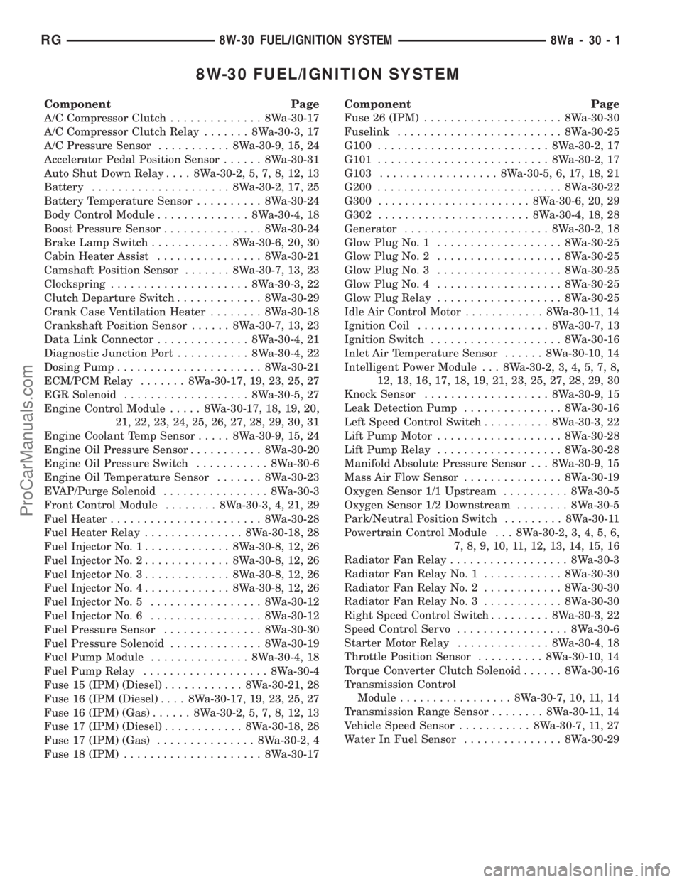
8W-30 FUEL/IGNITION SYSTEM
Component Page
A/C Compressor Clutch.............. 8Wa-30-17
A/C Compressor Clutch Relay....... 8Wa-30-3, 17
A/C Pressure Sensor........... 8Wa-30-9, 15, 24
Accelerator Pedal Position Sensor...... 8Wa-30-31
Auto Shut Down Relay.... 8Wa-30-2, 5, 7, 8, 12, 13
Battery..................... 8Wa-30-2, 17, 25
Battery Temperature Sensor.......... 8Wa-30-24
Body Control Module.............. 8Wa-30-4, 18
Boost Pressure Sensor............... 8Wa-30-24
Brake Lamp Switch............ 8Wa-30-6, 20, 30
Cabin Heater Assist................ 8Wa-30-21
Camshaft Position Sensor....... 8Wa-30-7, 13, 23
Clockspring..................... 8Wa-30-3, 22
Clutch Departure Switch............. 8Wa-30-29
Crank Case Ventilation Heater........ 8Wa-30-18
Crankshaft Position Sensor...... 8Wa-30-7, 13, 23
Data Link Connector.............. 8Wa-30-4, 21
Diagnostic Junction Port........... 8Wa-30-4, 22
Dosing Pump...................... 8Wa-30-21
ECM/PCM Relay....... 8Wa-30-17, 19, 23, 25, 27
EGR Solenoid................... 8Wa-30-5, 27
Engine Control Module..... 8Wa-30-17, 18, 19, 20,
21, 22, 23, 24, 25, 26, 27, 28, 29, 30, 31
Engine Coolant Temp Sensor..... 8Wa-30-9, 15, 24
Engine Oil Pressure Sensor........... 8Wa-30-20
Engine Oil Pressure Switch........... 8Wa-30-6
Engine Oil Temperature Sensor....... 8Wa-30-23
EVAP/Purge Solenoid................ 8Wa-30-3
Front Control Module........ 8Wa-30-3, 4, 21, 29
Fuel Heater....................... 8Wa-30-28
Fuel Heater Relay............... 8Wa-30-18, 28
Fuel Injector No. 1............. 8Wa-30-8, 12, 26
Fuel Injector No. 2............. 8Wa-30-8, 12, 26
Fuel Injector No. 3............. 8Wa-30-8, 12, 26
Fuel Injector No. 4............. 8Wa-30-8, 12, 26
Fuel Injector No. 5................. 8Wa-30-12
Fuel Injector No. 6................. 8Wa-30-12
Fuel Pressure Sensor............... 8Wa-30-30
Fuel Pressure Solenoid.............. 8Wa-30-19
Fuel Pump Module............... 8Wa-30-4, 18
Fuel Pump Relay................... 8Wa-30-4
Fuse 15 (IPM) (Diesel)............ 8Wa-30-21, 28
Fuse 16 (IPM (Diesel).... 8Wa-30-17, 19, 23, 25, 27
Fuse 16 (IPM) (Gas)...... 8Wa-30-2, 5, 7, 8, 12, 13
Fuse 17 (IPM) (Diesel)............ 8Wa-30-18, 28
Fuse 17 (IPM) (Gas)............... 8Wa-30-2, 4
Fuse 18 (IPM)..................... 8Wa-30-17Component Page
Fuse 26 (IPM)..................... 8Wa-30-30
Fuselink......................... 8Wa-30-25
G100.......................... 8Wa-30-2, 17
G101.......................... 8Wa-30-2, 17
G103.................. 8Wa-30-5, 6, 17, 18, 21
G200............................ 8Wa-30-22
G300....................... 8Wa-30-6, 20, 29
G302....................... 8Wa-30-4, 18, 28
Generator...................... 8Wa-30-2, 18
Glow Plug No. 1................... 8Wa-30-25
Glow Plug No. 2................... 8Wa-30-25
Glow Plug No. 3................... 8Wa-30-25
Glow Plug No. 4................... 8Wa-30-25
Glow Plug Relay................... 8Wa-30-25
Idle Air Control Motor............ 8Wa-30-11, 14
Ignition Coil.................... 8Wa-30-7, 13
Ignition Switch.................... 8Wa-30-16
Inlet Air Temperature Sensor...... 8Wa-30-10, 14
Intelligent Power Module . . . 8Wa-30-2, 3, 4, 5, 7, 8,
12, 13, 16, 17, 18, 19, 21, 23, 25, 27, 28, 29, 30
Knock Sensor................... 8Wa-30-9, 15
Leak Detection Pump............... 8Wa-30-16
Left Speed Control Switch.......... 8Wa-30-3, 22
Lift Pump Motor................... 8Wa-30-28
Lift Pump Relay................... 8Wa-30-28
Manifold Absolute Pressure Sensor . . . 8Wa-30-9, 15
Mass Air Flow Sensor............... 8Wa-30-19
Oxygen Sensor 1/1 Upstream.......... 8Wa-30-5
Oxygen Sensor 1/2 Downstream........ 8Wa-30-5
Park/Neutral Position Switch......... 8Wa-30-11
Powertrain Control Module . . . 8Wa-30-2, 3, 4, 5, 6,
7, 8, 9, 10, 11, 12, 13, 14, 15, 16
Radiator Fan Relay.................. 8Wa-30-3
Radiator Fan Relay No. 1............ 8Wa-30-30
Radiator Fan Relay No. 2............ 8Wa-30-30
Radiator Fan Relay No. 3............ 8Wa-30-30
Right Speed Control Switch......... 8Wa-30-3, 22
Speed Control Servo................. 8Wa-30-6
Starter Motor Relay.............. 8Wa-30-4, 18
Throttle Position Sensor.......... 8Wa-30-10, 14
Torque Converter Clutch Solenoid...... 8Wa-30-16
Transmission Control
Module................. 8Wa-30-7, 10, 11, 14
Transmission Range Sensor........ 8Wa-30-11, 14
Vehicle Speed Sensor........... 8Wa-30-7, 11, 27
Water In Fuel Sensor............... 8Wa-30-29
RG8W-30 FUEL/IGNITION SYSTEM8Wa-30-1
ProCarManuals.com
Page 802 of 2321

8W-40 INSTRUMENT CLUSTER
Component Page
Body Control Module . . 8Wa-40-2, 3, 4, 5, 6, 7, 8, 9,
10, 11
Brake Fluid Level Switch............. 8Wa-40-9
Clockspring........................ 8Wa-40-9
Diagnostic Junction Port . . 8Wa-40-2, 3, 4, 5, 6, 7, 8,
9, 12
Engine Control Module.......... 8Wa-40-8, 9, 12
Engine Coolant Temp Sensor........ 8Wa-40-7, 8
Engine Oil Pressure Sensor........... 8Wa-40-12
Engine Oil Pressure Switch........... 8Wa-40-12
Front Control Module................ 8Wa-40-9
Fuel Pump Module.................. 8Wa-40-2
Fuse 24 (IPM)...................... 8Wa-40-2
G200.................... 8Wa-40-2, 10, 11, 12
G300............................. 8Wa-40-9
Instrument Cluster . 8Wa-40-2, 3, 4, 5, 6, 7, 8, 9, 10,
11 , 1 2
Intelligent Power Module........... 8Wa-40-2, 9
Left Front Door Ajar Switch........... 8Wa-40-3
Left Front Door Lock Motor/Ajar Switch . . 8Wa-40-3
Left Sliding Door Control Module....... 8Wa-40-4
Left Sliding Door Latch Sensing Switch . . 8Wa-40-4
Left Sliding Door Lock Motor/Ajar Switch . 8Wa-40-4
Left Speed Control Switch............. 8Wa-40-9
Liftgate Ajar Switch................. 8Wa-40-3
Liftgate Cinch/Release Motor.......... 8Wa-40-3
Message Center.................. 8Wa-40-6, 12
Multi- Function Switch............... 8Wa-40-6
Occupant Restraint Controller......... 8Wa-40-2
Parking Brake Switch............ 8Wa-40-10, 11
Powertrain Control Module....... 8Wa-40-7, 9, 12
Right Front Door Ajar Switch.......... 8Wa-40-3
Right Front Door Lock Motor/Ajar Switch . 8Wa-40-3
Right Sliding Door Control Module...... 8Wa-40-5
Right Sliding Door Latch Sensing Switch . 8Wa-40-5
Right Sliding Door Lock Motor/Ajar Switch. 8Wa-40-5
Right Speed Control Switch........... 8Wa-40-9
Traction Control Switch............ 8Wa-40-7, 8
Transmission Control Module.......... 8Wa-40-7
Vehicle Speed Sensor............... 8Wa-40-7, 8
Washer Fluid Level Switch............ 8Wa-40-9
RG8W-40 INSTRUMENT CLUSTER8Wa-40-1
ProCarManuals.com