2001 DODGE TOWN AND COUNTRY oil pressure
[x] Cancel search: oil pressurePage 304 of 2321
- 31TH/OIL PUMP - STANDARD PROCEDURE)
(Refer to 21 - TRANSMISSION/TRANSAXLE/AU-
TOMATIC - 41TE/OIL PUMP - STANDARD PRO-
CEDURE)
(b) If oil pump volume is within specification, a
possible restriction in the cooler lines or cooler has
occurred.
(c) If oil pump volume is not within specification,
possible internal transmission restrictions, compo-
nent wear or damage has occurred. (Refer to 21 -
TRANSMISSION/TRANSAXLE/AUTOMATIC -
31TH - DIAGNOSIS AND TESTING) (Refer to 21 -
TRANSMISSION/TRANSAXLE/AUTOMATIC -
41TE - DIAGNOSIS AND TESTING)
(d) If an oil cooler restriction is suspected, per-
form further inspections and flow meter testing by
isolating components (i.e. lines, coolers).
(e) After a restriction is isolated, perform cooler
flush procedure. (Refer to 7 - COOLING/TRANS-
MISSION - STANDARD PROCEDURE)
(f) Re-test cooler flow. If cooler flow does not
exceed minimum specification, replace compo-
nent(s) as necessary.
STANDARD PROCEDURE - FLUSHING
COOLERS AND TUBES
The recommended procedure for cooler flushing is
to use Tool 6906 Cooler Flusher.
WARNING:
WEAR PROTECTIVE EYEWEAR THAT MEETS THE
REQUIREMENTS OF OSHA AND ANSI Z87.1±1968.
WEAR STANDARD INDUSTRIAL RUBBER GLOVES.
KEEP LIGHTED CIGARETTES, SPARKS, FLAMES,
AND OTHER IGNITION SOURCES AWAY FROM THE
AREA TO PREVENT THE IGNITION OF COMBUSTI-
BLE LIQUIDS AND GASES. KEEP A CLASS (B) FIRE
EXTINGUISHER IN THE AREA WHERE THE
FLUSHER WILL BE USED.
KEEP THE AREA WELL VENTILATED.
DO NOT LET FLUSHING SOLVENT COME IN CON-
TACT WITH YOUR EYES OR SKIN: IF EYE CONTAM-
INATION OCCURS, FLUSH EYES WITH WATER FOR15 TO 20 SECONDS. REMOVE CONTAMINATED
CLOTHING AND WASH AFFECTED SKIN WITH
SOAP AND WATER. SEEK MEDICAL ATTENTION.
(1) Remove cover plate filler plug on Tool 6906.
Fill reservoir 1/2 to 3/4 full of fresh flushing solution.
Use MopartTransmission Cooler Flush (MS-552) or
equivalent solution conforming to MS-552. Flushing
solvents are petroleum based solutions generally
used to clean automatic transmission components.
DO NOTuse solvents containing acids, water, gaso-
line, or any other corrosive liquids.
(2) Reinstall filler plug on Tool 6906.
(3) Verify pump power switch is turned OFF. Con-
nect red alligator clip to positive (+) battery post.
Connect black (-) alligator clip to a good ground.
NOTE: When flushing transmission cooler and
lines, ALWAYS reverse flush.
(4) Connect the BLUE pressure line to the OUT-
LET (From) cooler line.
(5) Connect the CLEAR return line to the INLET
(To) cooler line
(6) Turn pump ON for two to three minutes to
flush cooler and lines.
(7) Turn pump OFF.
(8) Disconnect CLEAR suction line from reservoir
at cover plate. Disconnect CLEAR return line at
cover plate, and place it in a drain pan.
(9) Turn pump ON for 30 seconds to purge flush-
ing solution from cooler and lines. Turn pump OFF.
(10) Place CLEAR suction line into a one quart
container of MopartATF+4 (Automatic Transmission
FluidÐType 9602).
(11) Turn pump ON until all transmission fluid is
removed from the one quart container and lines. This
purges any residual cleaning solvent from the trans-
mission cooler and lines. Turn pump OFF.
(12) Disconnect alligator clips from battery. Recon-
nect flusher lines to cover plate, and remove flushing
adapters from cooler lines.
RSTRANSMISSION7-37
TRANSMISSION (Continued)
ProCarManuals.com
Page 309 of 2321
COOLING SYSTEM DIAGNOSIS-DIESEL ENGINE
CONDITION POSSIBLE CAUSES CORRECTION
TEMPERATURE GAUGE
READS LOW1. Diesel engines, due to their
inherent effiency are slower to warm
up than gasoline powered engines,
and will operate at lower
temperatures when the vehicle is
unloaded.1. The low gauge reading may
be normal. Refer to thermostats
in the manual text for
information. See Thermostat
Diagnosis-Diesel Engine.
2. Is the temperature gauge
connected to the temperature gauge
coolant sensor on the engine?2. Check, the engine
temperature sensor connector
in the engine compartment.
3. Is the temperature gauge
operating OK?3. Check gauge operation.
Repair as necessary.
4. Coolant level low in cold ambient
temperatures accompanied with poor
heater performance.4. Check coolant level in the
coolant tank. Inspect system for
leaks. Repair leaks as
necessary. Refer to the Coolant
section for WARNINGS and
precautions before removing
the pressure cap.
5. Improper operation of internal
heater doors or heater controls.5. Inspect heater and repair as
necessary. Refer to Heating
and Air Conditioning for
procedures.
TEMPERATURE GAUGE
READS HIGH. COOLANT
MAY OR MAY NOT BE
LOST OR LEAKING FROM
COOLING SYSTEM1. Trailer is being towed, a steep hill
is being climbed, vehicle is operated
in slow moving traffic, or engine is
being idled with very high ambient
(outside) temperature and the air
conditioning is on. Higher altitudes
could aggravate these conditions.1. This may be a temporary
condition and repair is not
necessary. Turn off the air
conditioning and attempt to
drive the vehicle without any of
the previous conditions.
Observe the temperature
gauge. The gauge should return
to the normal range. If the
gauge does not return to
normal range, determine the
cause for the overheating and
repair.
2. Temperature gauge reading
incorrectly.2. Check gauge. Refer to I/P
group.
3. Coolant low in coolant tank and
radiator.3. Check for coolant leaks and
repair as necessary.
4. Pressure cap not installed tightly.
If cap is loose, boiling point of
coolant will be lowered.4. Tighten cap.
5. Poor seals at pressure/vent cap. 5. (a) Check condition of cap
and cap seals. (b) Check
condition of coolant tank filler
neck. Make sure it does not
leak pressure.
7a - 2 COOLING 2.5L TURBO DIESELRG
COOLING 2.5L TURBO DIESEL (Continued)
ProCarManuals.com
Page 311 of 2321
CONDITION POSSIBLE CAUSES CORRECTION
5. Coolant level low in the coolant
tank (air will build up in the cooling
system causing the thermostat to
open late).5. Check and correct coolant
leaks.
6. Cylinder head gasket leaking
allowing exhaust gases to enter the
cooling system causing the
thermostat to open late.6. (a) Check for cylinder head
gasket leaks with a
commercially available leak
tester. (b) Check for coolant in
engine oil. Inspect for white
steam emitting from exhaust
system. Repair as necessary.
7. Water pump impeller loose on
shaft.7. Check water pump and
replace as necessary.
8. Loose accessory drive belt (water
pump slipping).8. Check and correct as
necessary.
9. Air leak on the suction side of the
water pump allowing air to build up
in the cooling system causing the
thermostat to open late.9. Locate leak and repair as
necessary.
PRESSURE CAP IS
BLOWING OFF STEAM
AND/OR COOLANT.
TEMPERATURE GAUGE
READING MAY BE ABOVE
NORMAL BUT NOT HIGH.
COOLANT LEVEL MAY BE
HIGH IN COOLANT TANK1. Pressure relief valve in pressure/
vent cap is defective.1. Check condition of
pressure/vent cap and cap
seals.
2. Head gasket leak or cracked
cylinder head.2. Repair as necessary.
COOLANT LOSS TO THE
GROUND WITHOUT
PRESSURE CAP
BLOWOFF. GAUGE IS
READING HIGH OR HOT1. Coolant leaks in radiator, cooling
system hoses, water pump, or
engine.1. Pressure test cooling system
and repair as necessary.
HOSE OR HOSES
COLLAPSE WHEN
ENGINE IS COOLING1. Vacuum created in cooling system
on engine cool-down is not being
relieved through pressure/vent cap.1. Cap relief valve stuck.
Replace if necessary.
NOISY FAN 1. Cooling fan blades loose. 1. Replace cooling fan
assembly.
2. Cooling fan blades striking a
surrounding object.2. Locate point of fan blade
contact and repair as
necessary.
3. Air obstructions at radiator or A/C
condensor.3. Remove obstructions or
clean debris from radiator or
A/C condensor.
7a - 4 COOLING 2.5L TURBO DIESELRG
COOLING 2.5L TURBO DIESEL (Continued)
ProCarManuals.com
Page 313 of 2321
CONDITION POSSIBLE CAUSES CORRECTION
4. Has undercoating been applied to
any unnecessary components?4. Clean undercoating as
necessary.
STEAM IS COMING FROM
FRONT OF VEHICLE
NEAR GRILL AREA WHEN
WEATHER IS WET,
ENGINE IS WARMED UP
AND RUNNING, AND
VEHICLE IS STATIONARY.
TEMPERATURE GAUGE
IS IN NORMAL RANGE1. During wet weather, moisture
(snow, ice, or rain condensation) on
the radiator will evaporate when the
thermostat opens. This opening
allows heated water into the radiator.
When the moisture contacts the hot
radiator, steam may be emitted. This
usually occurs in cold weather with
no fan or airflow to blow it away.1. Occasional steam emitting
from this area is normal. No
repair is necessary.
COOLANT ODOR 1. Coolant color is not necessarily an
indication of adequate corrosion or
temperature protection. Do not rely
on coolant color for determining
condition of coolant.1. Refer to Coolant in this group
for antifreeze tests. Adjust
antifreeze-to-water ratio as
necessary.
COOLANT LEVEL
CHANGES IN COOLANT
TANK. TEMPERATURE
GAUGE IS IN NORMAL
RANGE1. Level changes are to be expected
as coolant volume fluctuates with
engine temperature. If the level in
the tank was between the HOT and
COLD marks at normal engine
operating temperature, the level
should return to within that range
after operation at elevated
temperatures.1. This a normal condition. No
repair necessary.
DIAGNOSIS AND TESTING - COOLING SYSTEM
LEAK TEST
WARNING: THE WARNING WORDS ªDO NOT OPEN
HOTº ON THE RADIATOR PRESSURE CAP IS A
SAFETY PRECAUTION. WHEN HOT, PRESSURE
BUILDS UP IN COOLING SYSTEM. TO PREVENT
SCALDING OR INJURY, THE RADIATOR CAP
SHOULD NOT BE REMOVED WHILE THE SYSTEM
IS HOT OR UNDER PRESSURE.
With engine not running, remove pressure/vent cap
from the coolant recovery pressure container and
wipe the filler neck sealing seat clean. The coolant
recovery pressure container should be full.
Attach the Cooling System Tester 7700 or equiva-
lent to the radiator, as shown in (Fig. 1) and apply
104 kPa (15 psi) pressure. If the pressure drops more
than 13.8 kPa (2 psi) in 2 minutes, inspect all points
for external leaks.
All radiator and heater hoses should be shaken
while at 104 kPa (15 psi), since some leaks occur only
while driving due to engine movement.
If there are no external leaks, after the gauge dial
shows a drop in pressure, detach the tester. Startengine and run until the thermostat opens, allowing
the coolant to expand. Reattach the cooling system
tester. If the needle on the dial fluctuates it indicates
a combustion leak, usually a head gasket leak.
WARNING: WITH TOOL IN PLACE, PRESSURE WILL
BUILD UP FAST. EXCESSIVE PRESSURE BUILT UP,
BY CONTINUOUS ENGINE OPERATION, MUST BE
RELEASED TO A SAFE PRESSURE POINT. NEVER
PERMIT PRESSURE TO EXCEED 138 kPa (20 psi).
If the needle on the dial does not fluctuate, raise
the engine rpm a few times. If an abnormal amount
of coolant or steam emits from the tailpipe, it may
indicate a coolant leak caused by a faulty head gas-
ket, cracked engine block, or cracked cylinder head.
There may be internal leaks that can be deter-
mined by removing the oil dipstick. If water globules
appear intermixed with the oil it will indicate an
internal leak in the engine. If there is an internal
leak, the engine must be disassembled for repair.
7a - 6 COOLING 2.5L TURBO DIESELRG
COOLING 2.5L TURBO DIESEL (Continued)
ProCarManuals.com
Page 322 of 2321
100 Percent Ethylene-GlycolÐShould Not Be Used in
Chrysler Vehicles
Use of 100 percent ethylene-glycol will cause for-
mation of additive deposits in the system, as the cor-
rosion inhibitive additives in ethylene-glycol require
the presence of water to dissolve. The deposits act as
insulation, causing temperatures to rise to as high as
149 deg. C (300 deg. F). This temperature is hot
enough to melt plastic and soften solder. The
increased temperature can result in engine detona-
tion. In addition, 100 percent ethylene-glycol freezes
at -22 deg. C (-8 deg. F ).
Propylene-glycol FormulationsÐShould Not Be Used in
Chrysler Vehicles
Propylene-glycol formulations do not meet
Chrysler coolant specifications.It's overall effec-
tive temperature range is smaller than that of ethyl-
ene-glycol. The freeze point of 50/50 propylene-glycol
and water is -32 deg. C (-26 deg. F). 5 deg. C higher
than ethylene-glycol's freeze point. The boiling point
(protection against summer boil-over) of propylene-
glycol is 125 deg. C (257 deg.F)at96.5 kPa (14 psi),
compared to 128 deg. C (263 deg. F) for ethylene-gly-
col. Use of propylene-glycol can result in boil-over or
freeze-up in Chrysler vehicles, which are designed for
ethylene-glycol. Propylene glycol also has poorer heat
transfer characteristics than ethylene glycol. This
can increase cylinder head temperatures under cer-
tain conditions.
Propylene-glycol/Ethylene-glycol MixturesÐShould Not Be
Used in Chrysler Vehicles
Propylene-glycol/ethylene-glycol Mixtures can
cause the destabilization of various corrosion inhibi-
tors, causing damage to the various cooling system
components. Also, once ethylene-glycol and propy-
lene-glycol based coolants are mixed in the vehicle,
conventional methods of determining freeze point will
not be accurate. Both the refractive index and spe-
cific gravity differ between ethylene glycol and propy-
lene glycol.
CAUTION: Richer antifreeze mixtures cannot be
measured with normal field equipment and can
cause problems associated with 100 percent ethyl-
ene-glycol.DIAGNOSIS AND TESTING - COOLANT
CONCENTRATION TESTING
Coolant concentration should be checked when any
additional coolant was added to system or after a
coolant drain, flush and refill. The coolant mixture
offers optimum engine cooling and protection against
corrosion when mixed to a freeze point of -37ÉC
(-34ÉF) to -59ÉC (-50ÉF). The use of a hydrometer or a
refractometer can be used to test coolant concentra-
tion.
A hydrometer will test the amount of glycol in a
mixture by measuring the specific gravity of the mix-
ture. The higher the concentration of ethylene glycol,
the larger the number of balls that will float, and
higher the freeze protection (up to a maximum of
60% by volume glycol).
A refractometer will test the amount of glycol in a
coolant mixture by measuring the amount a beam of
light bends as it passes through the fluid.
Some coolant manufactures use other types of gly-
cols into their coolant formulations. Propylene glycol
is the most common new coolant. However, propylene
glycol based coolants do not provide the same freez-
ing protection and corrosion protection and is not rec-
ommended.
CAUTION: Do not mix types of coolantÐcorrosion
protection will be severely reduced.
STANDARD PROCEDURE - COOLANT SERVICE
For engine coolant recommended service schedule,
(Refer to LUBRICATION & MAINTENANCE/MAIN-
TENANCE SCHEDULES - DESCRIPTION).
STANDARD PROCEDURE - ADDING
ADDITIONAL COOLANT
The pressure/vent cap should not be removed
from the coolant recovery pressure container.
When additional coolant is needed to maintain this
level, it should be added to the coolant recovery pres-
sure container (Fig. 1). Use only 50/50 mix of ethyl-
ene glycol type antifreeze and distilled water. For the
recommeded antifreeze/coolant type (Refer to LUBRI-
CATION & MAINTENANCE/FLUID TYPES -
DESCRIPTION).
CAUTION: Do not use well water, or suspect water
supply in cooling system. A 50/50 ethylene glycol
and distilled water mix is recommended. For the
recommeded antifreeze/coolant type (Refer to
LUBRICATION & MAINTENANCE/FLUID TYPES -
DESCRIPTION).
RGENGINE7a-15
COOLANT (Continued)
ProCarManuals.com
Page 323 of 2321
STANDARD PROCEDURE - COOLANT LEVEL
CHECK
NOTE: Do not remove pressure/vent cap for routine
coolant level inspections.
The coolant reserve system provides a quick visual
method for determining the coolant level without
removing the pressure/vent cap.With the engine
cold and not running,simply observe the level of
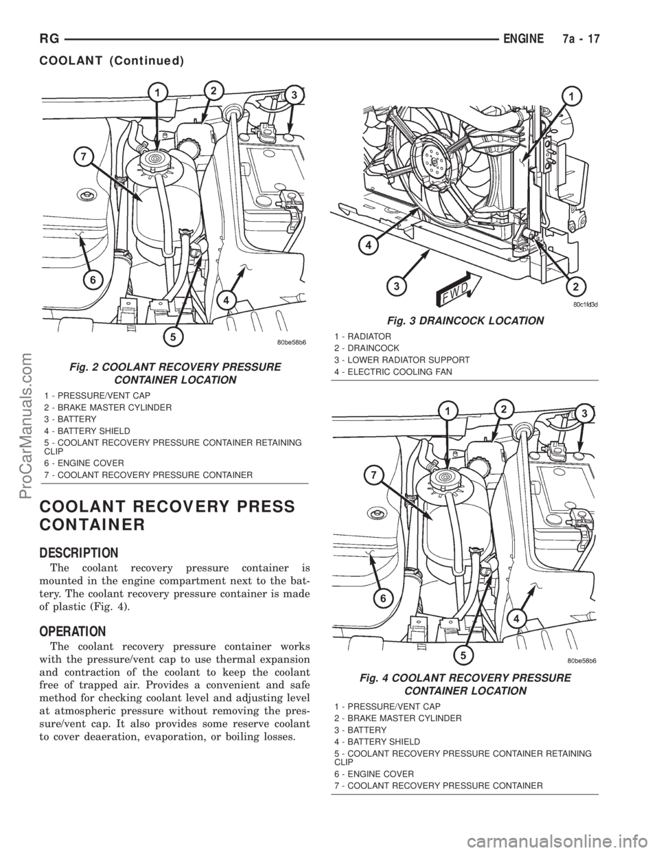
the coolant in the coolant recovery pressure container
(Fig. 2). The coolant level should be between the MIN
and MAX marks.
STANDARD PROCEDURE - REFILLING
COOLING SYSTEM
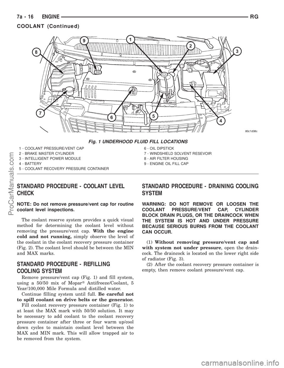
Remove pressure/vent cap (Fig. 1) and fill system,
using a 50/50 mix of MopartAntifreeze/Coolant, 5
Year/100,000 Mile Formula and distilled water.
Continue filling system until full.Be careful not
to spill coolant on drive belts or the generator.
Fill coolant recovery pressure container (Fig. 1) to
at least the MAX mark with 50/50 solution. It may
be necessary to add coolant to the coolant recovery
pressure container after three or four warm up/cool
down cycles to maintain coolant level between the
MAX and MIN mark. This will allow trapped air to
be removed from the system.
STANDARD PROCEDURE - DRAINING COOLING
SYSTEM
WARNING: DO NOT REMOVE OR LOOSEN THE
COOLANT PRESSURE/VENT CAP, CYLINDER
BLOCK DRAIN PLUGS, OR THE DRAINCOCK WHEN
THE SYSTEM IS HOT AND UNDER PRESSURE
BECAUSE SERIOUS BURNS FROM THE COOLANT
CAN OCCUR.
(1)Without removing pressure/vent cap and
with system not under pressure, open the drain-
cock. The draincock is located on the lower right side
of radiator (Fig. 3).
(2) After the coolant recovery pressure container is
empty, then remove coolant pressure/vent cap.
Fig. 1 UNDERHOOD FLUID FILL LOCATIONS
1 - COOLANT PRESSURE/VENT CAP
2 - BRAKE MASTER CYLINDER
3 - INTELLIGENT POWER MODULE
4 - BATTERY
5 - COOLANT RECOVERY PRESSURE CONTAINER6 - OIL DIPSTICK
7 - WINDSHIELD SOLVENT RESEVOIR
8 - AIR FILTER HOUSING
9 - ENGINE OIL FILL CAP
7a - 16 ENGINERG
COOLANT (Continued)
ProCarManuals.com
Page 324 of 2321
COOLANT RECOVERY PRESS
CONTAINER
DESCRIPTION
The coolant recovery pressure container is
mounted in the engine compartment next to the bat-
tery. The coolant recovery pressure container is made
of plastic (Fig. 4).
OPERATION
The coolant recovery pressure container works
with the pressure/vent cap to use thermal expansion
and contraction of the coolant to keep the coolant
free of trapped air. Provides a convenient and safe
method for checking coolant level and adjusting level
at atmospheric pressure without removing the pres-
sure/vent cap. It also provides some reserve coolant
to cover deaeration, evaporation, or boiling losses.
Fig. 2 COOLANT RECOVERY PRESSURE
CONTAINER LOCATION
1 - PRESSURE/VENT CAP
2 - BRAKE MASTER CYLINDER
3 - BATTERY
4 - BATTERY SHIELD
5 - COOLANT RECOVERY PRESSURE CONTAINER RETAINING
CLIP
6 - ENGINE COVER
7 - COOLANT RECOVERY PRESSURE CONTAINER
Fig. 3 DRAINCOCK LOCATION
1 - RADIATOR
2 - DRAINCOCK
3 - LOWER RADIATOR SUPPORT
4 - ELECTRIC COOLING FAN
Fig. 4 COOLANT RECOVERY PRESSURE
CONTAINER LOCATION
1 - PRESSURE/VENT CAP
2 - BRAKE MASTER CYLINDER
3 - BATTERY
4 - BATTERY SHIELD
5 - COOLANT RECOVERY PRESSURE CONTAINER RETAINING
CLIP
6 - ENGINE COVER
7 - COOLANT RECOVERY PRESSURE CONTAINER
RGENGINE7a-17
COOLANT (Continued)
ProCarManuals.com
Page 331 of 2321
RADIATOR PRESSURE CAP
DESCRIPTION
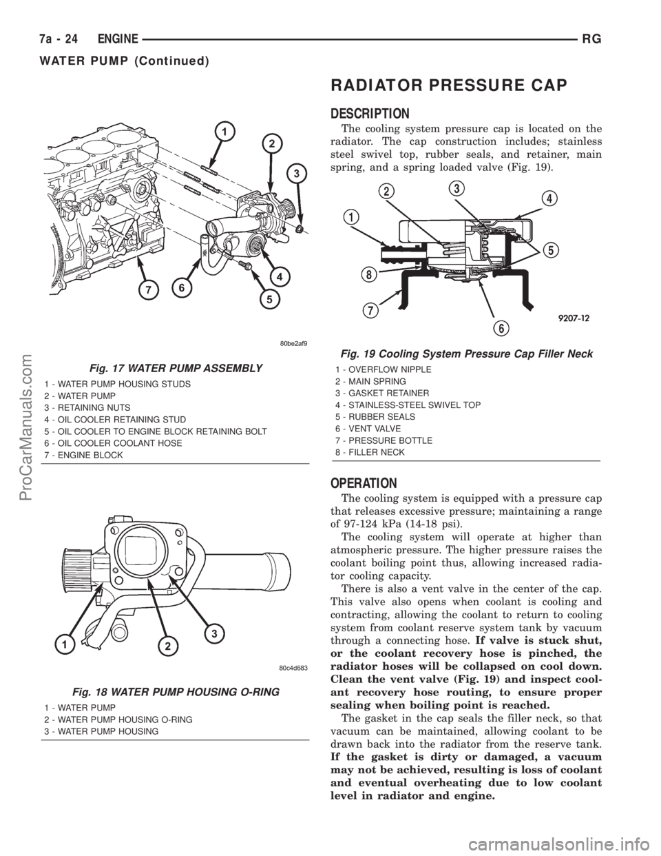
The cooling system pressure cap is located on the
radiator. The cap construction includes; stainless
steel swivel top, rubber seals, and retainer, main
spring, and a spring loaded valve (Fig. 19).
OPERATION
The cooling system is equipped with a pressure cap
that releases excessive pressure; maintaining a range
of 97-124 kPa (14-18 psi).
The cooling system will operate at higher than
atmospheric pressure. The higher pressure raises the
coolant boiling point thus, allowing increased radia-
tor cooling capacity.
There is also a vent valve in the center of the cap.
This valve also opens when coolant is cooling and
contracting, allowing the coolant to return to cooling
system from coolant reserve system tank by vacuum
through a connecting hose.If valve is stuck shut,
or the coolant recovery hose is pinched, the
radiator hoses will be collapsed on cool down.
Clean the vent valve (Fig. 19) and inspect cool-
ant recovery hose routing, to ensure proper
sealing when boiling point is reached.
The gasket in the cap seals the filler neck, so that
vacuum can be maintained, allowing coolant to be
drawn back into the radiator from the reserve tank.
If the gasket is dirty or damaged, a vacuum
may not be achieved, resulting is loss of coolant
and eventual overheating due to low coolant
level in radiator and engine.
Fig. 17 WATER PUMP ASSEMBLY
1 - WATER PUMP HOUSING STUDS
2 - WATER PUMP
3 - RETAINING NUTS
4 - OIL COOLER RETAINING STUD
5 - OIL COOLER TO ENGINE BLOCK RETAINING BOLT
6 - OIL COOLER COOLANT HOSE
7 - ENGINE BLOCK
Fig. 18 WATER PUMP HOUSING O-RING
1 - WATER PUMP
2 - WATER PUMP HOUSING O-RING
3 - WATER PUMP HOUSING
Fig. 19 Cooling System Pressure Cap Filler Neck
1 - OVERFLOW NIPPLE
2 - MAIN SPRING
3 - GASKET RETAINER
4 - STAINLESS-STEEL SWIVEL TOP
5 - RUBBER SEALS
6 - VENT VALVE
7 - PRESSURE BOTTLE
8 - FILLER NECK
7a - 24 ENGINERG
WATER PUMP (Continued)
ProCarManuals.com