Page 1858 of 2321

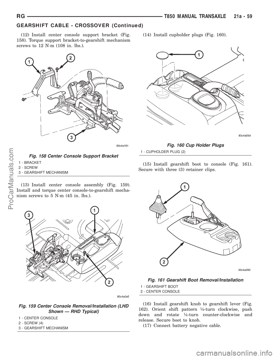
(12) Install center console support bracket (Fig.
158). Torque support bracket-to-gearshift mechanism
screws to 12 N´m (108 in. lbs.).
(13) Install center console assembly (Fig. 159).
Install and torque center console-to-gearshift mecha-
nism screws to 5 N´m (45 in. lbs.).(14) Install cupholder plugs (Fig. 160).
(15) Install gearshift boot to console (Fig. 161).
Secure with three (3) retainer clips.
(16) Install gearshift knob to gearshift lever (Fig.
162). Orient shift pattern ò-turn clockwise, push
down and rotate ò-turn counter-clockwise and
release. Secure boot to knob.
(17) Connect battery negative cable.
Fig. 158 Center Console Support Bracket
1 - BRACKET
2 - SCREW
3 - GEARSHIFT MECHANISM
Fig. 159 Center Console Removal/Installation (LHD
Shown Ð RHD Typical)
1 - CENTER CONSOLE
2 - SCREW (4)
3 - GEARSHIFT MECHANISM
Fig. 160 Cup Holder Plugs
1 - CUPHOLDER PLUG (2)
Fig. 161 Gearshift Boot Removal/Installation
1 - GEARSHIFT BOOT
2 - CENTER CONSOLE
RGT850 MANUAL TRANSAXLE21a-59
GEARSHIFT CABLE - CROSSOVER (Continued)
ProCarManuals.com
Page 1860 of 2321

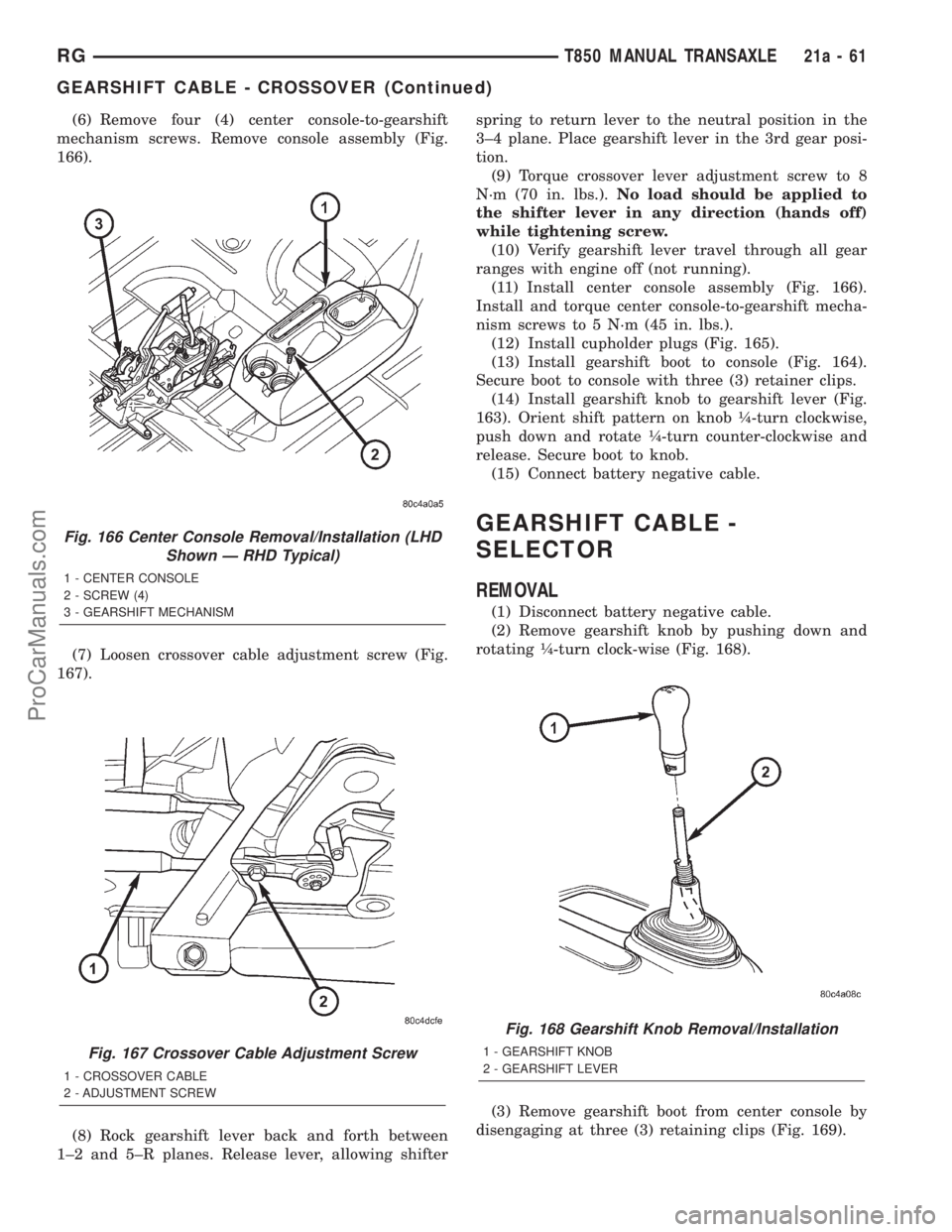
(6) Remove four (4) center console-to-gearshift
mechanism screws. Remove console assembly (Fig.
166).
(7) Loosen crossover cable adjustment screw (Fig.
167).
(8) Rock gearshift lever back and forth between
1±2 and 5±R planes. Release lever, allowing shifterspring to return lever to the neutral position in the
3±4 plane. Place gearshift lever in the 3rd gear posi-
tion.
(9) Torque crossover lever adjustment screw to 8
N´m (70 in. lbs.).No load should be applied to
the shifter lever in any direction (hands off)
while tightening screw.
(10) Verify gearshift lever travel through all gear
ranges with engine off (not running).
(11) Install center console assembly (Fig. 166).
Install and torque center console-to-gearshift mecha-
nism screws to 5 N´m (45 in. lbs.).
(12) Install cupholder plugs (Fig. 165).
(13) Install gearshift boot to console (Fig. 164).
Secure boot to console with three (3) retainer clips.
(14) Install gearshift knob to gearshift lever (Fig.
163). Orient shift pattern on knob ò-turn clockwise,
push down and rotate ò-turn counter-clockwise and
release. Secure boot to knob.
(15) Connect battery negative cable.
GEARSHIFT CABLE -
SELECTOR
REMOVAL
(1) Disconnect battery negative cable.
(2) Remove gearshift knob by pushing down and
rotating ò-turn clock-wise (Fig. 168).
(3) Remove gearshift boot from center console by
disengaging at three (3) retaining clips (Fig. 169).
Fig. 166 Center Console Removal/Installation (LHD
Shown Ð RHD Typical)
1 - CENTER CONSOLE
2 - SCREW (4)
3 - GEARSHIFT MECHANISM
Fig. 167 Crossover Cable Adjustment Screw
1 - CROSSOVER CABLE
2 - ADJUSTMENT SCREW
Fig. 168 Gearshift Knob Removal/Installation
1 - GEARSHIFT KNOB
2 - GEARSHIFT LEVER
RGT850 MANUAL TRANSAXLE21a-61
GEARSHIFT CABLE - CROSSOVER (Continued)
ProCarManuals.com
Page 1865 of 2321
(10) Install selector cable to gearshift mechanism
(Fig. 185). Install retainer clip (Fig. 186).(11) Install center console support bracket (Fig.
187). Torque support bracket-to-gearshift mechanism
screws to 12 N´m (108 in. lbs.).
(12) Install center console assembly (Fig. 188).
Install and torque center console-to-gearshift mecha-
nism screws to 5 N´m (45 in. lbs.).
Fig. 185 Selector Cable at Gearshift Mechanism
1 - GEARSHIFT MECHANISM
2 - SELECTOR CABLE
Fig. 186 Selector Cable Retainer Clip
1 - RETAINER CLIP
Fig. 187 Center Console Support Bracket
1 - BRACKET
2 - SCREW
3 - GEARSHIFT MECHANISM
Fig. 188 Center Console Removal/Installation (LHD
Shown Ð RHD Typical)
1 - CENTER CONSOLE
2 - SCREW (4)
3 - GEARSHIFT MECHANISM
21a - 66 T850 MANUAL TRANSAXLERG
GEARSHIFT CABLE - SELECTOR (Continued)
ProCarManuals.com
Page 1869 of 2321
(11) Remove selector cable from gearshift mecha-
nism (Fig. 201).
(12) Remove four (4) gearshift mechanism-to-park
brake bracket nuts. Remove gearshift mechanism
from bracket (Fig. 202).INSTALLATION
(1) Install gearshift mechanism to park brake
bracket (Fig. 203). Install and torque nuts to 12 N´m
(108 in. lbs.).
(2) Install selector cable to gearshift mechanism
(Fig. 204). Install retainer clip (Fig. 205).
Fig. 201 Selector Cable at Gearshift Mechanism
1 - GEARSHIFT MECHANISM
2 - SELECTOR CABLE
Fig. 202 Gearshift Mechanism Removal/Installation
(RHD Shown Ð LHD Typical)
1 - GEARSHIFT MECHANISM
2 - PARK BRAKE BRACKET
3 - NUT (4)
Fig. 203 Gearshift Mechanism Removal/Installation
(RHD Shown Ð LHD Typical)
1 - GEARSHIFT MECHANISM
2 - PARK BRAKE BRACKET
3 - NUT (4)
Fig. 204 Selector Cable at Gearshift Mechanism
1 - GEARSHIFT MECHANISM
2 - SELECTOR CABLE
21a - 70 T850 MANUAL TRANSAXLERG
GEARSHIFT MECHANISM (Continued)
ProCarManuals.com
Page 1870 of 2321
(3) Install crossover cable to gearshift mechanism
(Fig. 206). Install retainer clip (Fig. 207).(4) Adjust crossover cable.
(5) Install center console support bracket (Fig.
208). Torque support bracket-to-gearshift mechanism
screws to 12 N´m (108 in. lbs.).
Fig. 205 Selector Cable Retainer Clip
1 - RETAINER CLIP
Fig. 206 Crossover Cable at Gearshift Mechanism
1 - GEARSHIFT MECHANISM
2 - CROSSOVER CABLE
Fig. 207 Crossover Cable Retainer Clip
1 - RETAINER CLIP
2 - CROSSOVER CABLE
Fig. 208 Center Console Support Bracket
1 - BRACKET
2 - SCREW
3 - GEARSHIFT MECHANISM
RGT850 MANUAL TRANSAXLE21a-71
GEARSHIFT MECHANISM (Continued)
ProCarManuals.com
Page 1871 of 2321
(6) Install center console assembly (Fig. 209).
Install and torque center console-to-gearshift mecha-
nism screws to 5 N´m (45 in. lbs.).
(7) Install cupholder plugs (Fig. 210).(8) Install gearshift boot to console (Fig. 211).
Secure with three (3) retainer clips.
(9) Install gearshift knob to gearshift lever (Fig.
212). Orient shift pattern ò-turn clockwise, push
down and rotate ò-turn counter-clockwise and
release. Secure boot to knob.
(10) Connect battery negative cable.
Fig. 209 Center Console Removal/Installation (LHD
Shown Ð RHD Typical)
1 - CENTER CONSOLE
2 - SCREW (4)
3 - GEARSHIFT MECHANISM
Fig. 210 Cup Holder Plugs
1 - CUPHOLDER PLUG (2)
Fig. 211 Gearshift Boot Removal/Installation
1 - GEARSHIFT BOOT
2 - CENTER CONSOLE
Fig. 212 Gearshift Knob Removal/Installation
1 - GEARSHIFT KNOB
2 - GEARSHIFT LEVER
21a - 72 T850 MANUAL TRANSAXLERG
GEARSHIFT MECHANISM (Continued)
ProCarManuals.com
Page 1878 of 2321
(7) Install 4th gear blocker ring (Fig. 229).
(8) Install 4th gear (Fig. 230).
(9) Install 5th gear and press into position using
installer 8481 (Fig. 231).
(10) InstallNEW5th gear nut and torque to 200
N´m (148 ft. lbs.) using wrench 8478 (Fig. 232).
(11) Stake 5th Gear nut as follows:
(a) Install staking tool 8479 to 5th gear nut.(b) Tighten upper thumb screw by hand (Fig.
233).
(c) Tighten two (2) side thumb screws by hand.
Fig. 229 4th Gear Blocker Ring
1 - 4th GEAR BLOCKER RING
Fig. 230 4th Gear Removal/Installation
1 - 4th GEAR
Fig. 231 5th Gear Installation
1 - ARBOR PRESS RAM
2 - INSTALLER 8481
3 - 5TH GEAR
Fig. 232 5th Gear Nut Removal/Installation
1 - WRENCH 8478
2 - 5TH GEAR NUT
RGT850 MANUAL TRANSAXLE21a-79
INPUT SHAFT (Continued)
ProCarManuals.com
Page 1895 of 2321

(2) Install springs into hub slot.
(3) Insert key into hub and spring.
(4) Apply petroleum jelly to the hole in the key.
Insert balls into each key.
(5) Slide sleeve over the hub and depress balls as
you carefully slip the sleeve into position.
VEHICLE SPEED SENSOR
REMOVAL
(1) Raise vehicle on hoist.
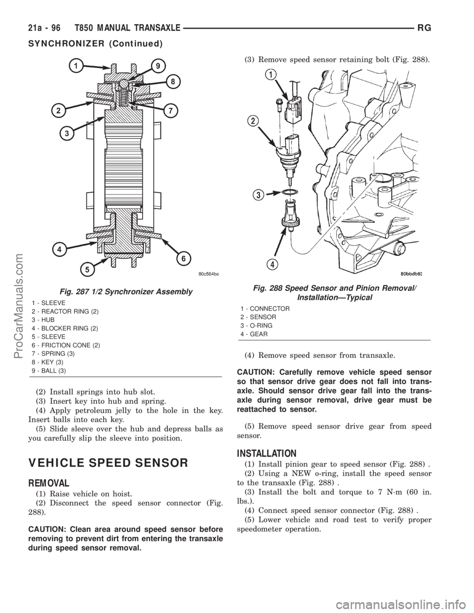
(2) Disconnect the speed sensor connector (Fig.
288).
CAUTION: Clean area around speed sensor before
removing to prevent dirt from entering the transaxle
during speed sensor removal.(3) Remove speed sensor retaining bolt (Fig. 288).
(4) Remove speed sensor from transaxle.
CAUTION: Carefully remove vehicle speed sensor
so that sensor drive gear does not fall into trans-
axle. Should sensor drive gear fall into the trans-
axle during sensor removal, drive gear must be
reattached to sensor.
(5) Remove speed sensor drive gear from speed
sensor.
INSTALLATION
(1) Install pinion gear to speed sensor (Fig. 288) .
(2) Using a NEW o-ring, install the speed sensor
to the transaxle (Fig. 288) .
(3) Install the bolt and torque to 7 N´m (60 in.
lbs.).
(4) Connect speed sensor connector (Fig. 288) .
(5) Lower vehicle and road test to verify proper
speedometer operation.
Fig. 287 1/2 Synchronizer Assembly
1 - SLEEVE
2 - REACTOR RING (2)
3 - HUB
4 - BLOCKER RING (2)
5 - SLEEVE
6 - FRICTION CONE (2)
7 - SPRING (3)
8 - KEY (3)
9 - BALL (3)
Fig. 288 Speed Sensor and Pinion Removal/
InstallationÐTypical
1 - CONNECTOR
2 - SENSOR
3 - O-RING
4 - GEAR
21a - 96 T850 MANUAL TRANSAXLERG
SYNCHRONIZER (Continued)
ProCarManuals.com