2001 DODGE TOWN AND COUNTRY check engine
[x] Cancel search: check enginePage 2181 of 2321
ELECTRICAL/ELECTRONIC CONTROL MOD-
ULES/POWERTRAIN CONTROL MODULE -
DESCRIPTION - PCM OPERATION).
STANDARD PROCEDURE - COMPRESSOR
CLUTCH AIR GAP
If a new clutch plate and/or clutch pulley are being
used, the air gap between the clutch plate and clutch
pulley must be checked using the following proce-
dure:
(1) Using feeler gauges, measure the air gap
between the clutch plate and the clutch pulley fric-
tion surfaces.
(2) If the air gap is not between 0.5 and 0.9 mm
(0.020 and 0.035 in.), add or subtract shims until the
desired air gap is obtained.
NOTE: The shims may compress after tightening
the compressor shaft bolt. Check the air gap in four
or more places on the clutch plate to verify that the
air gap is still correct. Spin the clutch pulley before
making the final air gap check.
STANDARD PROCEDURE - COMPRESSOR
CLUTCH BREAK-IN
After a new compressor clutch has been installed,
check that the compressor clutch coil is performing to
specifications. (Refer to 24 - HEATING & AIR CON-
DITIONING/CONTROLS - FRONT/COMPRESSOR
CLUTCH COIL - DIAGNOSIS AND TESTING). If
the clutch coil is performing to specifications, per-
form the compressor clutch break-in procedure. This
procedure (burnishing) will seat the opposing friction
surfaces and provide a higher compressor clutch
torque capability.
(1) Set the heater-A/C controls to the A/C mode,
with the blower switch in the highest speed position.
(2) Start the engine and hold the engine speed at
1500 to 2000 rpm.
(3) Cycle the compressor clutch On and Off about
twenty times (five seconds On, then five seconds Off).
REMOVAL
The refrigerant system can remain fully charged
during compressor clutch, pulley, or coil replacement.
Although the compressor assembly must be removed
from its mounting, the compressor clutch can be ser-
vice with the compressor in the vehicle.
(1) Disconnect and isolate the battery negative
cable.
(2) Raise and support the vehicle.
(3) Remove the serpentine drive belt. (Refer to 7 -
COOLING/ACCESSORY DRIVE/DRIVE BELTS -
2.4L - REMOVAL) or (Refer to 7 - COOLING/ACCES-SORY DRIVE/DRIVE BELTS - 3.3/3.8L - REMOV-
AL).
(4) Disconnect the engine wire harness connector
for the compressor clutch coil from the clutch coil pig-
tail wire connector on the top of the compressor.
(5) On models with the 3.3L and 3.8L engines, dis-
engage the retainer on the engine wire harness com-
pressor clutch coil take out from the bracket on the
top of the compressor.
(6) On models with the 2.4L engine, remove all of
the compressor mounting screws except the upper
left (rear of the compressor) screw, which should only
be loosened. Allow the front (pulley end) of the com-
pressor to tilt downward far enough to access the
clutch for removal, then tighten the loosened upper
left compressor mounting screw.
(7) On models with the 3.3L and 3.8L engines,
remove the three screws and one nut that secure the
compressor to the engine. Disengage the mounting
ear at the front of the compressor from the stud on
the engine, allow the front (pulley end) of the com-
pressor to tilt downward far enough to access the
clutch for removal, then reinstall and tighten the
upper left compressor mounting screw.
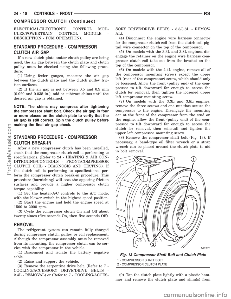
(8) Remove the compressor shaft bolt (Fig. 13). If
necessary, a band-type oil filter wrench or a strap
wrench can be placed around the clutch plate to aid
in bolt removal.
(9) Tap the clutch plate lightly with a plastic ham-
mer and remove the clutch plate and shim(s) from
Fig. 13 Compressor Shaft Bolt and Clutch Plate
1 - COMPRESSOR SHAFT BOLT
2 - COMPRESSOR CLUTCH PLATE
24 - 18 CONTROLS - FRONTRS
COMPRESSOR CLUTCH (Continued)
ProCarManuals.com
Page 2183 of 2321
packing from around the compressor shaft in the
compressor front cover. If the felt is saturated with
oil, the compressor front shaft seal is leaking and the
compressor will also have to be replaced.
(3) Check the clutch pulley bearing for roughness
or excessive leakage of grease. Replace the clutch
pulley and clutch plate if the bearing is faulty.
INSTALLATION
The refrigerant system can remain fully charged
during compressor clutch, pulley, or coil replacement.
Although the compressor assembly must be removed
from its mounting, the compressor clutch can be ser-
vice with the compressor in the vehicle.
(1) Align the dowel pin on the back of the clutch
coil with the hole in the compressor front cover, and
position the clutch coil onto the compressor. Be cer-
tain that the clutch coil pigtail wires are properly ori-
ented and routed so that they are not pinched
between the compressor front cover and the clutch
coil.
NOTE: A new snap ring must be used to secure the
clutch coil to the compressor. The bevel side of the
snap ring must face outward.
(2) Using snap ring pliers (Special Tool C-4574 or
equivalent), install the external snap ring that
secures the clutch coil to the front cover of the com-
pressor (Fig. 16). The bevel side of the snap ring
must face outward and both snap ring eyelets must
be oriented to the right or the left of the clutch coil
dowel pin location on the compressor. Be certain that
the snap ring is fully and properly seated in the
groove.
CAUTION: If the snap ring is not fully seated in the
groove it will vibrate out, resulting in a clutch fail-
ure and severe damage to the compressor front
cover.
(3) Install and tighten the screw that secures the
clutch coil pigtail wire connector bracket and ground
clip to the top of the compressor housing.
(4) Install the pulley onto the front cover of the
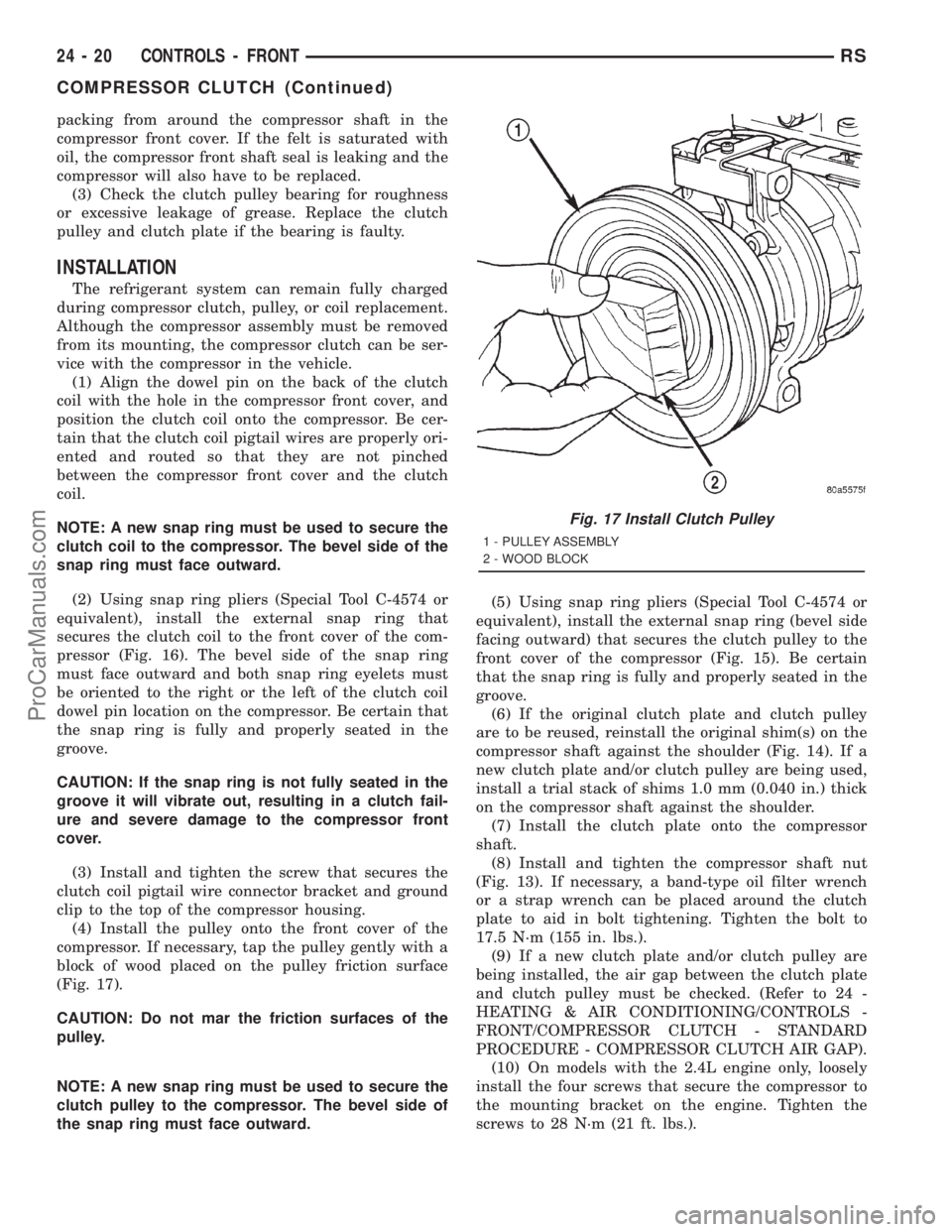
compressor. If necessary, tap the pulley gently with a
block of wood placed on the pulley friction surface
(Fig. 17).
CAUTION: Do not mar the friction surfaces of the
pulley.
NOTE: A new snap ring must be used to secure the
clutch pulley to the compressor. The bevel side of
the snap ring must face outward.(5) Using snap ring pliers (Special Tool C-4574 or
equivalent), install the external snap ring (bevel side
facing outward) that secures the clutch pulley to the
front cover of the compressor (Fig. 15). Be certain
that the snap ring is fully and properly seated in the
groove.
(6) If the original clutch plate and clutch pulley
are to be reused, reinstall the original shim(s) on the
compressor shaft against the shoulder (Fig. 14). If a
new clutch plate and/or clutch pulley are being used,
install a trial stack of shims 1.0 mm (0.040 in.) thick
on the compressor shaft against the shoulder.
(7) Install the clutch plate onto the compressor
shaft.
(8) Install and tighten the compressor shaft nut
(Fig. 13). If necessary, a band-type oil filter wrench
or a strap wrench can be placed around the clutch
plate to aid in bolt tightening. Tighten the bolt to
17.5 N´m (155 in. lbs.).
(9) If a new clutch plate and/or clutch pulley are
being installed, the air gap between the clutch plate
and clutch pulley must be checked. (Refer to 24 -
HEATING & AIR CONDITIONING/CONTROLS -
FRONT/COMPRESSOR CLUTCH - STANDARD
PROCEDURE - COMPRESSOR CLUTCH AIR GAP).
(10) On models with the 2.4L engine only, loosely
install the four screws that secure the compressor to
the mounting bracket on the engine. Tighten the
screws to 28 N´m (21 ft. lbs.).
Fig. 17 Install Clutch Pulley
1 - PULLEY ASSEMBLY
2 - WOOD BLOCK
24 - 20 CONTROLS - FRONTRS
COMPRESSOR CLUTCH (Continued)
ProCarManuals.com
Page 2184 of 2321
(11) On models with the 3.3L and 3.8L engines
only, loosely install the three screws and one nut that
secure the compressor to the engine. Tighten each of
the fasteners using the following sequence to 54 N´m
(40 ft. lbs.).
²The upper screw at the rear of the compressor.
²The lower screw at the rear of the compressor.
²The lower screw at the front of the compressor.
²The upper nut at the front of the compressor.
(12) On models with the 3.3L and 3.8L engines
only, engage the retainer on the engine wire harness
compressor clutch coil take out with the bracket on
the top of the compressor.
(13) Reconnect the engine wire harness connector
for the compressor clutch coil to the coil pigtail wire
connector on the top of the compressor.
(14) Reinstall the serpentine accessory drive belt
onto the front of the engine. (Refer to 7 - COOLING/
ACCESSORY DRIVE/DRIVE BELTS - 2.4L -
INSTALLATION) or (Refer to 7 - COOLING/ACCES-
SORY DRIVE/DRIVE BELTS - 3.3L/3.8L - INSTAL-
LATION).
(15) Lower the vehicle.
(16) Reconnect the battery negative cable.
(17) If a new clutch plate and/or clutch pulley are
being installed, the new clutch components must be
burnished. (Refer to 24 - HEATING & AIR CONDI-
TIONING/CONTROLS - FRONT/COMPRESSOR
CLUTCH - STANDARD PROCEDURE - COMPRES-
SOR CLUTCH BREAK-IN).
COMPRESSOR CLUTCH COIL
DIAGNOSIS AND TESTING - COMPRESSOR
CLUTCH COIL
The air conditioning compressor clutch coil electri-
cal circuit is controlled by the Powertrain Control
Module (PCM) through the compressor clutch relay,
which is located in the Intelligent Power Module
(IPM) in the engine compartment near the battery.
Begin testing of a suspected compressor clutch coil
problem by performing the preliminary checks.
PRELIMINARY CHECKS
(1) If the compressor clutch will not engage, verify
the refrigerant charge level. (Refer to 24 - HEATING
& AIR CONDITIONING/PLUMBING - FRONT/RE-
FRIGERANT - DIAGNOSIS AND TESTING -
REFRIGERANT CHARGE LEVEL). If the refriger-
ant charge level is OK, go to Step 2. If the refriger-
ant charge level is not OK, adjust the refrigerant
charge as required.
(2) If the a/c compressor clutch still will not
engage, disconnect the headlamp and dash wire har-
ness connector for the A/C pressure transducer andcheck for battery current at the connector with the
engine running and the heater-A/C control set to the
A/C mode. If OK, go to TESTS . If not OK, use a
DRBIIItscan tool to perform further diagnosis. Refer
to the appropriate diagnostic information.
TESTS
(1) Verify the battery state of charge. (Refer to 8 -
ELECTRICAL/BATTERY SYSTEM/BATTERY -
DIAGNOSIS AND TESTING).
(2) Connect an ammeter (0 to 10 ampere scale
selected) in series with the clutch coil feed terminal.
Connect a voltmeter (0 to 20 volt scale selected) to
measure voltage across the battery and the clutch
coil.
(3) With the heater-A/C control in the A/C mode
and the blower at low speed, start the engine and
allow it to run at a normal idle speed.
(4) The compressor clutch should engage immedi-
ately, and the clutch coil voltage should be within
two volts of the battery voltage. If the coil voltage is
not within two volts of battery voltage, test the
clutch coil feed circuit for excessive voltage drop. If
the compressor clutch does not engage, use a
DRBIIItscan tool to perform further diagnosis. Refer
to the appropriate diagnostic information.
(5) With the ambient temperature at 21É C (70É F),
the compressor clutch coil is acceptable if the current
draw is 2.0 to 3.7 amperes at 11.5 to 12.5 volts at the
clutch coil. If the voltage is more than 12.5 volts, add
electrical loads by turning on electrical accessories
until the voltage reads below 12.5 volts.
(a) If the compressor clutch coil current reading
is zero, the coil is open and must be replaced.
(b) If the compressor clutch coil current reading
is four amperes or more, the coil is shorted and
must be replaced.
COMPRESSOR CLUTCH RELAY
DESCRIPTION
The compressor clutch relay (Fig. 18) is a Interna-
tional Standards Organization (ISO) micro-relay.
Relays conforming to the ISO specifications have
common physical dimensions, current capacities, ter-
minal patterns, and terminal functions. The ISO
micro-relay terminal functions are the same as a con-
ventional ISO relay. However, the ISO micro-relay
terminal pattern (or footprint) is different, the cur-
rent capacity is lower, and the physical dimensions
are smaller than those of the conventional ISO relay.
The compressor clutch relay is located in the Intelli-
gent Power Module (IPM), which is in the engine
compartment near the battery. See the fuse and relay
layout map molded into the inner surface of the IPM
RSCONTROLS - FRONT24-21
COMPRESSOR CLUTCH (Continued)
ProCarManuals.com
Page 2219 of 2321
system control switch on the front heater-A/C control
is not in the Off position. The blower motor can only
be turned off by turning off the rear system at the
front heater-A/C control. The blower motor receives
battery current whenever the rear blower motor
relay is energized. The rear blower motor relay out-
put circuit is protected by a fuse in the Intelligent
Power Module (IPM) located in the engine compart-
ment near the battery. In the MTC system, the
blower motor speed is controlled by regulating the
path to ground through the blower control switch and
the blower motor resistor. In the ATC system, the
blower motor speed is controlled by an electronic
blower power module, which uses a pulse width mod-
ulated input from the ATC module and feedback from
the blower motor to regulate the blower motor
ground path it provides. The blower motor and wheel
are used to control the velocity of air moving through
the rear heater-A/C unit housing. The blower motor
controls the velocity of the air flowing through the
rear heater-A/C housing by spinning the blower
wheel within the housing at the selected speed or, in
the ATC system, at the selected or programmed
speed.
DIAGNOSIS AND TESTING - REAR BLOWER
MOTOR
BLOWER MOTOR INOPERATIVE
(1) Check the fuse (Fuse 12 - 25 ampere) in the
Intelligent Power Module (IPM). If OK, go to Step 2.
If not OK, repair the shorted circuit or component as
required and replace the faulty fuse.
(2) Turn the ignition switch to the On position. Be
certain that the rear heater-A/C control power is
turned on. Check for battery voltage at the fuse
(Fuse 12 - 25 ampere) in the IPM. If OK, go to Step
3. If not OK, proceed to diagnosis of the rear blower
motor relay. (Refer to 24 - HEATING & AIR CONDI-TIONING/CONTROLS - REAR/BLOWER MOTOR
RELAY - DIAGNOSIS AND TESTING).
(3) Turn the ignition switch to the Off position.
Disconnect and isolate the battery negative cable.
Disconnect the rear HVAC wire harness connector for
the rear blower motor resistor (Manual Temperature
Control) or the rear blower power module (Automatic
Temperature Control) from the resistor or module
connector receptacle. Reconnect the battery negative
cable. Turn the ignition switch to the On position. Be
certain that the rear heater-A/C control power is
turned on. Check for battery voltage at the fused
rear blower motor relay output circuit cavity of the
rear HVAC wire harness connector for the rear
blower motor resistor (MTC) or the rear blower
power module (ATC). If OK, go to Step 4. If not OK,
repair the open fused front blower motor relay output
circuit to the IPM as required.
(4) Turn the ignition switch to the Off position.
Disconnect and isolate the battery negative cable.
Disconnect the rear blower motor pigtail wire connec-
tor from the take out and connector of the rear
HVAC wire harness (MTC) or the connector recepta-
cle of the rear blower power module (ATC). Use
jumper wires to connect a battery and ground feeds
to the blower motor pigtail wire connector. The
blower motor should operate. If OK with MTC, pro-
ceed to diagnosis of the rear blower motor resistor.
(Refer to 24 - HEATING & AIR CONDITIONING/
CONTROLS - REAR/BLOWER MOTOR RESISTOR -
DIAGNOSIS AND TESTING). If OK with ATC, use a
DRBIII scan tool to diagnose the rear blower power
module. Refer to the appropriate diagnostic informa-
tion. If not OK with MTC or ATC, replace the faulty
rear blower motor.
BLOWER MOTOR NOISE OR VIBRATION
Refer to the Blower Motor Noise/Vibration Diagno-
sis chart (Fig. 4).
24 - 56 DISTRIBUTION - REARRS
BLOWER MOTOR (Continued)
ProCarManuals.com
Page 2229 of 2321
(9) Remove the seal from the discharge line fitting
and discard.
(10) Install plugs in, or tape over the opened dis-
charge line fitting and the compressor discharge port.
(11) Raise and support the vehicle.
(12) Remove the serpentine accessory drive belt
from the front of the engine. (Refer to 7 - COOLING/
ACCESSORY DRIVE/DRIVE BELTS - 2.4L -
REMOVAL) or (Refer to 7 - COOLING/ACCESSORY
DRIVE/DRIVE BELTS - 3.3L/3.8L - REMOVAL).
(13) Disconnect the engine wire harness connector
for the compressor clutch coil from the coil pigtail
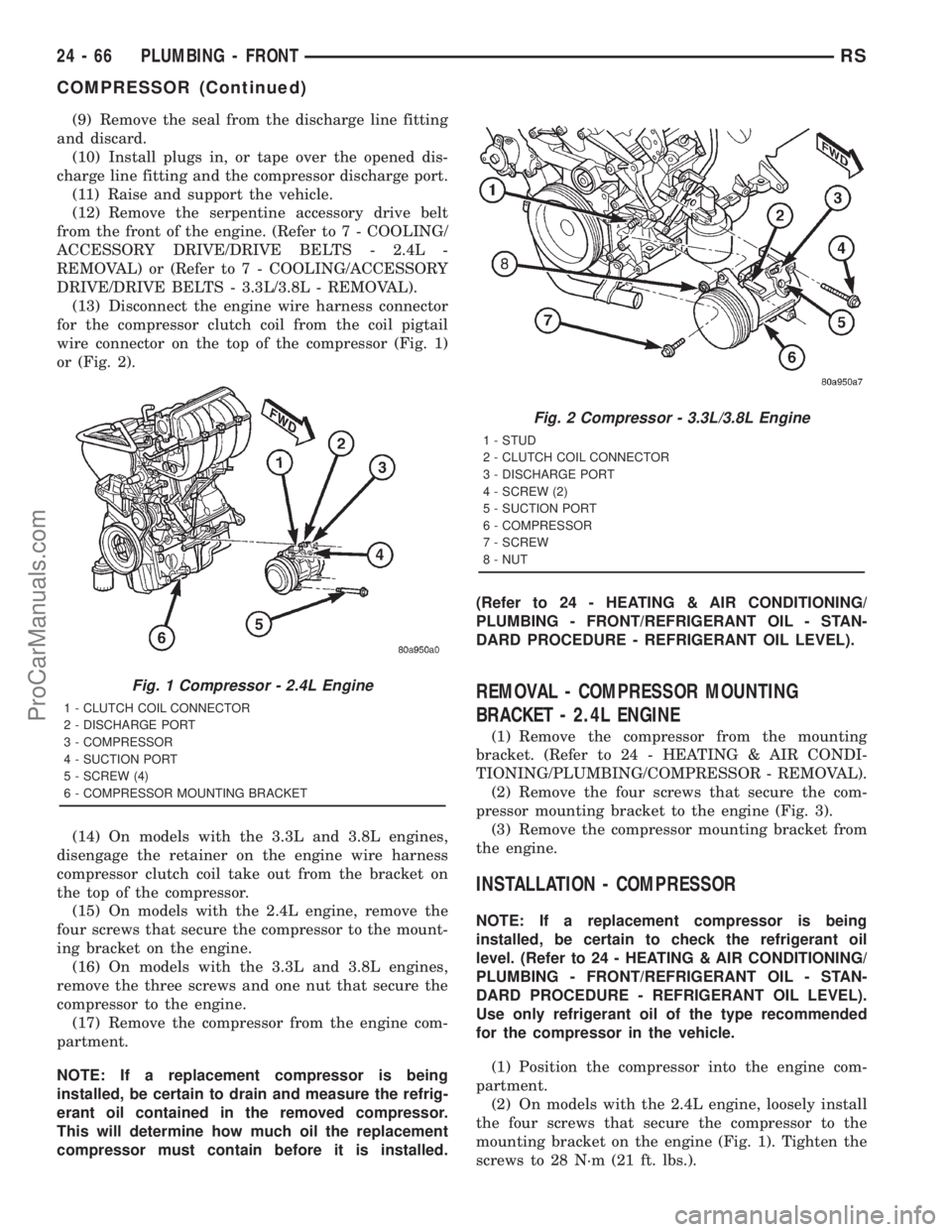
wire connector on the top of the compressor (Fig. 1)
or (Fig. 2).
(14) On models with the 3.3L and 3.8L engines,
disengage the retainer on the engine wire harness
compressor clutch coil take out from the bracket on
the top of the compressor.
(15) On models with the 2.4L engine, remove the
four screws that secure the compressor to the mount-
ing bracket on the engine.
(16) On models with the 3.3L and 3.8L engines,
remove the three screws and one nut that secure the
compressor to the engine.
(17) Remove the compressor from the engine com-
partment.
NOTE: If a replacement compressor is being
installed, be certain to drain and measure the refrig-
erant oil contained in the removed compressor.
This will determine how much oil the replacement
compressor must contain before it is installed.(Refer to 24 - HEATING & AIR CONDITIONING/
PLUMBING - FRONT/REFRIGERANT OIL - STAN-
DARD PROCEDURE - REFRIGERANT OIL LEVEL).
REMOVAL - COMPRESSOR MOUNTING
BRACKET - 2.4L ENGINE
(1) Remove the compressor from the mounting
bracket. (Refer to 24 - HEATING & AIR CONDI-
TIONING/PLUMBING/COMPRESSOR - REMOVAL).
(2) Remove the four screws that secure the com-
pressor mounting bracket to the engine (Fig. 3).
(3) Remove the compressor mounting bracket from
the engine.
INSTALLATION - COMPRESSOR
NOTE: If a replacement compressor is being
installed, be certain to check the refrigerant oil
level. (Refer to 24 - HEATING & AIR CONDITIONING/
PLUMBING - FRONT/REFRIGERANT OIL - STAN-
DARD PROCEDURE - REFRIGERANT OIL LEVEL).
Use only refrigerant oil of the type recommended
for the compressor in the vehicle.
(1) Position the compressor into the engine com-
partment.
(2) On models with the 2.4L engine, loosely install
the four screws that secure the compressor to the
mounting bracket on the engine (Fig. 1). Tighten the
screws to 28 N´m (21 ft. lbs.).
Fig. 1 Compressor - 2.4L Engine
1 - CLUTCH COIL CONNECTOR
2 - DISCHARGE PORT
3 - COMPRESSOR
4 - SUCTION PORT
5 - SCREW (4)
6 - COMPRESSOR MOUNTING BRACKET
Fig. 2 Compressor - 3.3L/3.8L Engine
1 - STUD
2 - CLUTCH COIL CONNECTOR
3 - DISCHARGE PORT
4 - SCREW (2)
5 - SUCTION PORT
6 - COMPRESSOR
7 - SCREW
8 - NUT
24 - 66 PLUMBING - FRONTRS
COMPRESSOR (Continued)
ProCarManuals.com
Page 2232 of 2321
INSTALLATION
NOTE: If the condenser is being replaced, add 30
milliliters (1 fluid ounce) of refrigerant oil to the
refrigerant system. Use only refrigerant oil of the
type recommended for the compressor in the vehi-
cle.
NOTE: Be certain that each of the radiator and con-
denser air seals are reinstalled in their proper loca-
tions. These air seals are required in order for the
air conditioning and engine cooling systems to per-
form as designed.
(1) Position the condenser to the right mounting
bracket and transmission oil cooler unit.
(2) Position the left mounting bracket onto the side
of the condenser and transmission oil cooler.
(3) Install and tighten the one screw that secures
the left mounting bracket to the side of the transmis-
sion oil cooler. Tighten the screw to 5 N´m (45 in.
lbs.).
(4) Install and tighten the two screws that secure
each mounting bracket to the sides of the condenser.
Tighten the screws to 5 N´m (45 in. lbs.).(5) Position the condenser, transmission oil cooler,
and mounting brackets into the vehicle as a unit. Be
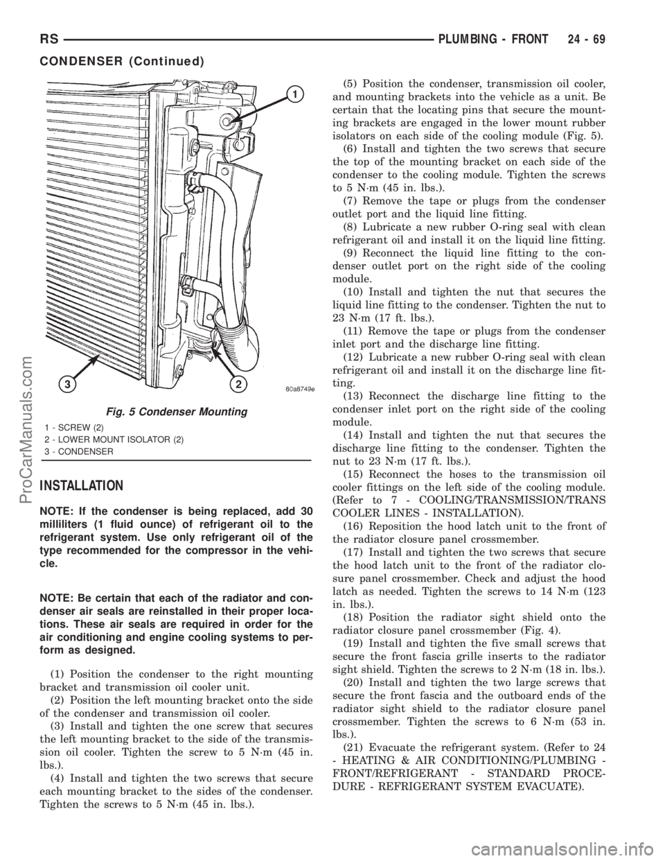
certain that the locating pins that secure the mount-
ing brackets are engaged in the lower mount rubber
isolators on each side of the cooling module (Fig. 5).
(6) Install and tighten the two screws that secure
the top of the mounting bracket on each side of the
condenser to the cooling module. Tighten the screws
to 5 N´m (45 in. lbs.).
(7) Remove the tape or plugs from the condenser
outlet port and the liquid line fitting.
(8) Lubricate a new rubber O-ring seal with clean
refrigerant oil and install it on the liquid line fitting.
(9) Reconnect the liquid line fitting to the con-
denser outlet port on the right side of the cooling
module.
(10) Install and tighten the nut that secures the
liquid line fitting to the condenser. Tighten the nut to
23 N´m (17 ft. lbs.).
(11) Remove the tape or plugs from the condenser
inlet port and the discharge line fitting.
(12) Lubricate a new rubber O-ring seal with clean
refrigerant oil and install it on the discharge line fit-
ting.
(13) Reconnect the discharge line fitting to the
condenser inlet port on the right side of the cooling
module.
(14) Install and tighten the nut that secures the
discharge line fitting to the condenser. Tighten the
nut to 23 N´m (17 ft. lbs.).
(15) Reconnect the hoses to the transmission oil
cooler fittings on the left side of the cooling module.
(Refer to 7 - COOLING/TRANSMISSION/TRANS
COOLER LINES - INSTALLATION).
(16) Reposition the hood latch unit to the front of
the radiator closure panel crossmember.
(17) Install and tighten the two screws that secure
the hood latch unit to the front of the radiator clo-
sure panel crossmember. Check and adjust the hood
latch as needed. Tighten the screws to 14 N´m (123
in. lbs.).
(18) Position the radiator sight shield onto the
radiator closure panel crossmember (Fig. 4).
(19) Install and tighten the five small screws that
secure the front fascia grille inserts to the radiator
sight shield. Tighten the screws to 2 N´m (18 in. lbs.).
(20) Install and tighten the two large screws that
secure the front fascia and the outboard ends of the
radiator sight shield to the radiator closure panel
crossmember. Tighten the screws to 6 N´m (53 in.
lbs.).
(21) Evacuate the refrigerant system. (Refer to 24
- HEATING & AIR CONDITIONING/PLUMBING -
FRONT/REFRIGERANT - STANDARD PROCE-
DURE - REFRIGERANT SYSTEM EVACUATE).
Fig. 5 Condenser Mounting
1 - SCREW (2)
2 - LOWER MOUNT ISOLATOR (2)
3 - CONDENSER
RSPLUMBING - FRONT24-69
CONDENSER (Continued)
ProCarManuals.com
Page 2251 of 2321
NOTE: When connecting the service equipment
couplings to the refrigerant system service ports,
be certain that the valve of each coupling is fully
closed. This will reduce the amount of effort
required to make the connection.
(1) Remove the caps from the refrigerant system
service ports and attach a manifold gauge set or a
R-134a refrigerant recovery/recycling/charging sta-
tion that meets SAE Standard J2210 to the refriger-
ant system.
(2) Attach a clamp-on thermocouple to the liquid
line. The thermocouple must be placed as close to the
A/C pressure transducer as possible to accurately
observe liquid line temperature.
(3) Bring the refrigerant system up to operating
temperature and pressure. This is done by allowing
the engine to run at idle under the following condi-
tions for five minutes.
(a) Front windows are open.
(b) Transaxle in Park.
(c) Front heater-A/C controls set to outside air,
full cool, panel mode, blower high, and compressor
engaged.
(d) If the vehicle is so equipped, the rear heater-
A/C controls must be set to full cool and blower
high.(4) Raise the liquid line (discharge) pressure to
about 1793 kPa (260 psi) by placing a piece of card-
board over part of the front side of the condenser. To
place the cardboard properly, remove the upper radi-
ator sight shield from the front fascia. Cover only
enough of the condenser to raise and maintain the
liquid line pressure at the specified level.
(5) Observe the liquid line (discharge) pressure
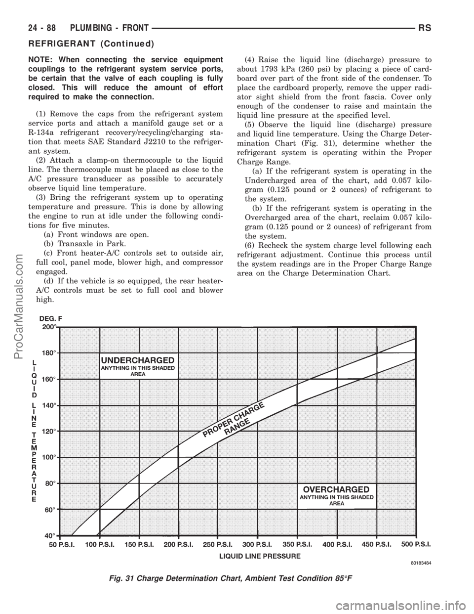
and liquid line temperature. Using the Charge Deter-
mination Chart (Fig. 31), determine whether the
refrigerant system is operating within the Proper
Charge Range.
(a) If the refrigerant system is operating in the
Undercharged area of the chart, add 0.057 kilo-
gram (0.125 pound or 2 ounces) of refrigerant to
the system.
(b) If the refrigerant system is operating in the
Overcharged area of the chart, reclaim 0.057 kilo-
gram (0.125 pound or 2 ounces) of refrigerant from
the system.
(6) Recheck the system charge level following each
refrigerant adjustment. Continue this process until
the system readings are in the Proper Charge Range
area on the Charge Determination Chart.
Fig. 31 Charge Determination Chart, Ambient Test Condition 85ÉF
24 - 88 PLUMBING - FRONTRS
REFRIGERANT (Continued)
ProCarManuals.com
Page 2255 of 2321
ND-8 PAG refrigerant oil. Use only refrigerant oil of
this same type to service the refrigerant system.
OPERATION
After performing any refrigerant recovery or recy-
cling operation, always replenish the refrigerant sys-
tem with the same amount of the recommended
refrigerant oil as was removed. Too little refrigerant
oil can cause compressor damage, and too much can
reduce air conditioning system performance. PAG
refrigerant oil is much more hygroscopic than min-
eral oil, and will absorb any moisture it comes into
contact with, even moisture in the air. The PAG oil
container should always be kept tightly capped until
it is ready to be used. After use, recap the oil con-
tainer immediately to prevent moisture contamina-
tion.
STANDARD PROCEDURE - REFRIGERANT OIL
LEVEL
WARNING: REFER TO THE APPLICABLE WARN-
INGS AND CAUTIONS FOR THIS SYSTEM BEFORE
PERFORMING THE FOLLOWING OPERATION.
(Refer to 24 - HEATING & AIR CONDITIONING/
PLUMBING - FRONT - WARNING - A/C PLUMBING)
and (Refer to 24 - HEATING & AIR CONDITIONING/
PLUMBING - FRONT - CAUTION - A/C PLUMBING).
When an air conditioning system is assembled at
the factory, all components except the compressor are
refrigerant oil free. After the refrigerant system has
been charged and operated, the refrigerant oil in the
compressor is dispersed throughout the refrigerant
system. The receiver/drier, evaporator, condenser, and
compressor will each retain a significant amount of
the needed refrigerant oil.
It is important to have the correct amount of oil in
the refrigerant system. This ensures proper lubrica-
tion of the compressor. Too little oil will result in
damage to the compressor. Too much oil will reduce
the cooling capacity of the air conditioning system.
It will not be necessary to check the oil level in the
compressor or to add oil, unless there has been an oil
loss. An oil loss may occur due to a rupture or leak
from a refrigerant line, a connector fitting, a compo-
nent, or a component seal. If a leak occurs, add 30
milliliters (1 fluid ounce) of refrigerant oil to the
refrigerant system after the repair has been made.
Refrigerant oil loss will be evident at the leak point
by the presence of a wet, shiny surface around the
leak.
Refrigerant oil must be added when an receiver/
drier, evaporator or condenser is replaced. See the
Refrigerant Oil Capacities chart for the proper
amount of refrigerant oil to add. When a compressoris replaced, the refrigerant oil must be drained from
the old compressor and measured. Drain all of the
refrigerant oil from the new compressor, then fill the
new compressor with the same amount of fresh new
refrigerant oil that was drained out of the old com-
pressor.
REFRIGERANT OIL CAPACITIES
Front A/C Front & Rear
A/C
COMPONENT ml fl oz ml fl oz
Compressor 150 5.0 220 7.4
Filter-Drier 30 1.0 30 1.0
Condenser 30 1.0 30 1.0
Front Evaporator 60 2.0 60 2.0
Rear Evap. (including
underbody lines)N/A N/A 60 2.0
Compressor Drain and measure the oil
from the old compressor -
See text above.
SUCTION LINE
REMOVAL
The front air conditioner suction line includes the
low side service port on a section of tubing located
near the compressor. On models equipped with the
optional rear air conditioner, the front air conditioner
suction line also includes a suction line hose and
tube extension that connects the front suction line to
the suction line for the rear air conditioner.
WARNING: REFER TO THE APPLICABLE WARN-
INGS AND CAUTIONS FOR THIS SYSTEM BEFORE
PERFORMING THE FOLLOWING OPERATION.
(Refer to 24 - HEATING & AIR CONDITIONING/
PLUMBING - FRONT - WARNING - A/C PLUMBING)
and (Refer to 24 - HEATING & AIR CONDITIONING/
PLUMBING - FRONT - CAUTION - A/C PLUMBING).
(1) Recover the refrigerant from the refrigerant
system. (Refer to 24 - HEATING & AIR CONDI-
TIONING/PLUMBING - FRONT/REFRIGERANT -
STANDARD PROCEDURE - REFRIGERANT
RECOVERY).
(2) Disconnect and isolate the battery negative
cable.
(3) Remove the air cleaner top cover and snorkel
from the air cleaner housing located on the right side
of the engine compartment.
(4) Disconnect the drain tube from the wiper mod-
ule drain on the right side of the engine compart-
ment.
24 - 92 PLUMBING - FRONTRS
REFRIGERANT OIL (Continued)
ProCarManuals.com