2001 DODGE TOWN AND COUNTRY check engine
[x] Cancel search: check enginePage 1810 of 2321
DIAGNOSIS AND TESTING - COMMON
PROBLEM CAUSES
The majority of transaxle malfunctions are a result
of:
²Insufficient lubrication
²Incorrect lubricant
²Misassembled or damaged internal components
²Improper operation
HARD SHIFTING
Hard shifting may be caused by a misadjusted
crossover cable. If hard shifting is accompanied by
gear clash, synchronizer clutch and stop rings or gear
teeth may be worn or damaged.
Hard shifting may also be caused by a binding or
broken shift cover mechanism. Remove shift cover
and verify smooth operation. Replace as necessary.
Misassembled synchronizer components also cause
shifting problems. Incorrectly installed synchronizer
sleeves, keys, balls, or springs can cause shift prob-
lems.
NOISY OPERATION
Transaxle noise is most often a result of worn or
damaged components. Chipped, broken gear or syn-
chronizer teeth, and brinnelled, spalled bearings all
cause noise.
Abnormal wear and damage to the internal compo-
nents is frequently the end result of insufficient
lubricant.
SLIPS OUT OF GEAR
Transaxle disengagement may be caused by mis-
aligned or damaged shift components, or worn teeth
on the drive gears or synchronizer components. Incor-
rect assembly also causes gear disengagement. Check
for missing snap rings.
LOW LUBRICANT LEVEL
Insufficient transaxle lubricant is usually the
result of leaks, or inaccurate fluid level check or refill
method. Leakage is evident by the presence of oil
around the leak point. If leakage is not evident, the
condition is probably the result of an underfill.
If air±powered lubrication equipment is used to fill
a transaxle, be sure the equipment is properly cali-
brated. Equipment out of calibration can lead to an
underfill condition.
CLUTCH PROBLEMS
Worn, damaged, or misaligned clutch components
can cause difficult shifting, gear clash, and noise.
A worn or damaged clutch disc, pressure plate, or
release bearing can cause hard shifting and gear
clash.
REMOVAL
REMOVAL - 2.4L GAS
(1) Raise hood.
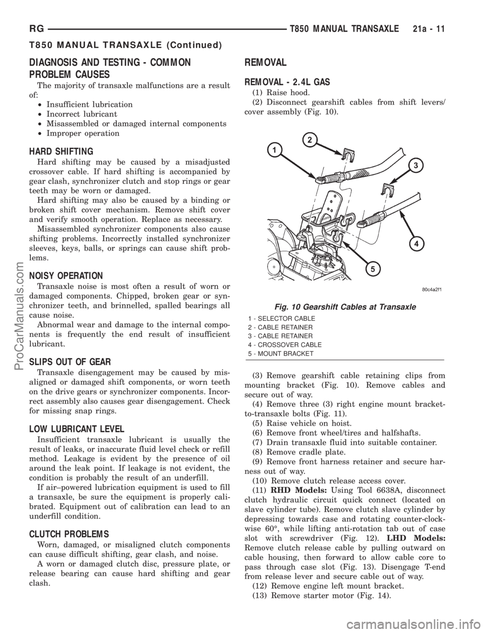
(2) Disconnect gearshift cables from shift levers/
cover assembly (Fig. 10).
(3) Remove gearshift cable retaining clips from
mounting bracket (Fig. 10). Remove cables and
secure out of way.
(4) Remove three (3) right engine mount bracket-
to-transaxle bolts (Fig. 11).
(5) Raise vehicle on hoist.
(6) Remove front wheel/tires and halfshafts.
(7) Drain transaxle fluid into suitable container.
(8) Remove cradle plate.
(9) Remove front harness retainer and secure har-
ness out of way.
(10) Remove clutch release access cover.
(11)RHD Models:Using Tool 6638A, disconnect
clutch hydraulic circuit quick connect (located on
slave cylinder tube). Remove clutch slave cylinder by
depressing towards case and rotating counter-clock-
wise 60É, while lifting anti-rotation tab out of case
slot with screwdriver (Fig. 12).LHD Models:
Remove clutch release cable by pulling outward on
cable housing, then forward to allow cable core to
pass through case slot (Fig. 13). Disengage T-end
from release lever and secure cable out of way.
(12) Remove engine left mount bracket.
(13) Remove starter motor (Fig. 14).
Fig. 10 Gearshift Cables at Transaxle
1 - SELECTOR CABLE
2 - CABLE RETAINER
3 - CABLE RETAINER
4 - CROSSOVER CABLE
5 - MOUNT BRACKET
RGT850 MANUAL TRANSAXLE21a-11
T850 MANUAL TRANSAXLE (Continued)
ProCarManuals.com
Page 1832 of 2321
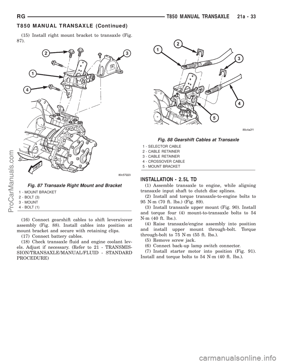
(15) Install right mount bracket to transaxle (Fig.
87).
(16) Connect gearshift cables to shift levers/cover
assembly (Fig. 88). Install cables into position at
mount bracket and secure with retaining clips.
(17) Connect battery cables.
(18) Check transaxle fluid and engine coolant lev-
els. Adjust if necessary. (Refer to 21 - TRANSMIS-
SION/TRANSAXLE/MANUAL/FLUID - STANDARD
PROCEDURE)
INSTALLATION - 2.5L TD
(1) Assemble transaxle to engine, while aligning
transaxle input shaft to clutch disc splines.
(2) Install and torque transaxle-to-engine bolts to
95 N´m (70 ft. lbs.) (Fig. 89).
(3) Install transaxle upper mount (Fig. 90). Install
and torque four (4) mount-to-transaxle bolts to 54
N´m (40 ft. lbs.).
(4) Raise transaxle/engine assembly into position
and install upper mount through-bolt. Torque
through-bolt to 75 N´m (55 ft. lbs.).
(5) Remove screw jack.
(6) Connect back-up lamp switch connector.
(7) Install starter motor into position (Fig. 91).
Install and torque bolts to 54 N´m (40 ft. lbs.).Fig. 87 Transaxle Right Mount and Bracket
1 - MOUNT BRACKET
2 - BOLT (3)
3 - MOUNT
4 - BOLT (1)
Fig. 88 Gearshift Cables at Transaxle
1 - SELECTOR CABLE
2 - CABLE RETAINER
3 - CABLE RETAINER
4 - CROSSOVER CABLE
5 - MOUNT BRACKET
RGT850 MANUAL TRANSAXLE21a-33
T850 MANUAL TRANSAXLE (Continued)
ProCarManuals.com
Page 1836 of 2321
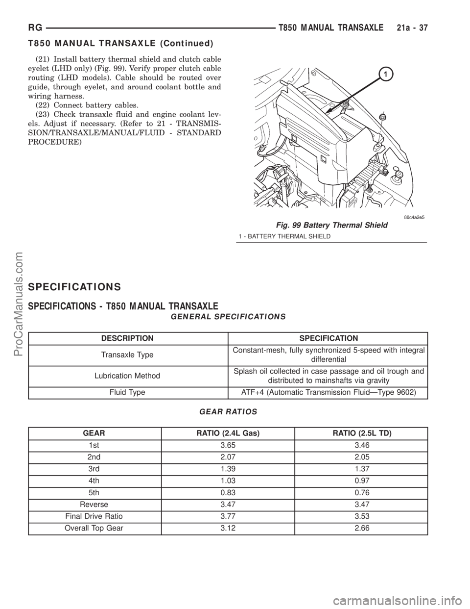
(21) Install battery thermal shield and clutch cable
eyelet (LHD only) (Fig. 99). Verify proper clutch cable
routing (LHD models). Cable should be routed over
guide, through eyelet, and around coolant bottle and
wiring harness.
(22) Connect battery cables.
(23) Check transaxle fluid and engine coolant lev-
els. Adjust if necessary. (Refer to 21 - TRANSMIS-
SION/TRANSAXLE/MANUAL/FLUID - STANDARD
PROCEDURE)
SPECIFICATIONS
SPECIFICATIONS - T850 MANUAL TRANSAXLE
GENERAL SPECIFICATIONS
DESCRIPTION SPECIFICATION
Transaxle TypeConstant-mesh, fully synchronized 5-speed with integral
differential
Lubrication MethodSplash oil collected in case passage and oil trough and
distributed to mainshafts via gravity
Fluid Type ATF+4 (Automatic Transmission FluidÐType 9602)
GEAR RATIOS
GEAR RATIO (2.4L Gas) RATIO (2.5L TD)
1st 3.65 3.46
2nd 2.07 2.05
3rd 1.39 1.37
4th 1.03 0.97
5th 0.83 0.76
Reverse 3.47 3.47
Final Drive Ratio 3.77 3.53
Overall Top Gear 3.12 2.66
Fig. 99 Battery Thermal Shield
1 - BATTERY THERMAL SHIELD
RGT850 MANUAL TRANSAXLE21a-37
T850 MANUAL TRANSAXLE (Continued)
ProCarManuals.com
Page 1923 of 2321
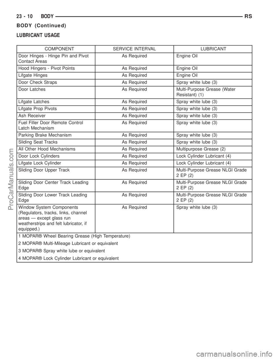
LUBRICANT USAGE
COMPONENT SERVICE INTERVAL LUBRICANT
Door Hinges - Hinge Pin and Pivot
Contact AreasAs Required Engine Oil
Hood Hingers - Pivot Points As Required Engine Oil
Lifgate Hinges As Required Engine Oil
Door Check Straps As Required Spray white lube (3)
Door Latches As Required Multi-Purpose Grease (Water
Resistant) (1)
Lifgate Latches As Required Spray white lube (3)
Lifgate Prop Pivots As Required Spray white lube (3)
Ash Receiver As Required Spray white lube (3)
Fuel Filler Door Remote Control
Latch MechanismAs Required Spray white lube (3)
Parking Brake Mechanism As Required Spray white lube (3)
Sliding Seat Tracks As Required Spray white lube (3)
All Other Hood Mechanisms As Required Multipurpose Grease (2)
Door Lock Cylinders As Required Lock Cylinder Lubricant (4)
Lifgate Lock Cylinder As Required Lock Cylinder Lubricant (4)
Sliding Door Upper Track As Required Multi-Purpose Grease NLGI Grade
2 EP (2)
Sliding Door Center Track Leading
EdgeAs Required Multi-Purpose Grease NLGI Grade
2 EP (2)
Sliding Door Lower Track Leading
EdgeAs Required Multi-Purpose Grease NLGI Grade
2 EP (2)
Window System Components
(Regulators, tracks, links, channel
areas Ð except glass run
weatherstrips and felt lubricator, if
equipped.)As Required Spray white lube (3)
1 MOPARž Wheel Bearing Grease (High Temperature)
2 MOPARž Multi-Mileage Lubricant or equivalent
3 MOPARž Spray white lube or equivalent
4 MOPARž Lock Cylinder Lubricant or equivalent
23 - 10 BODYRS
BODY (Continued)
ProCarManuals.com
Page 2103 of 2321
COWL GRILLE
REMOVAL
(1) Remove wiper arms. (Refer to 8 - ELECTRI-
CAL/WIPERS/WASHERS/WIPER ARMS -
REMOVAL)
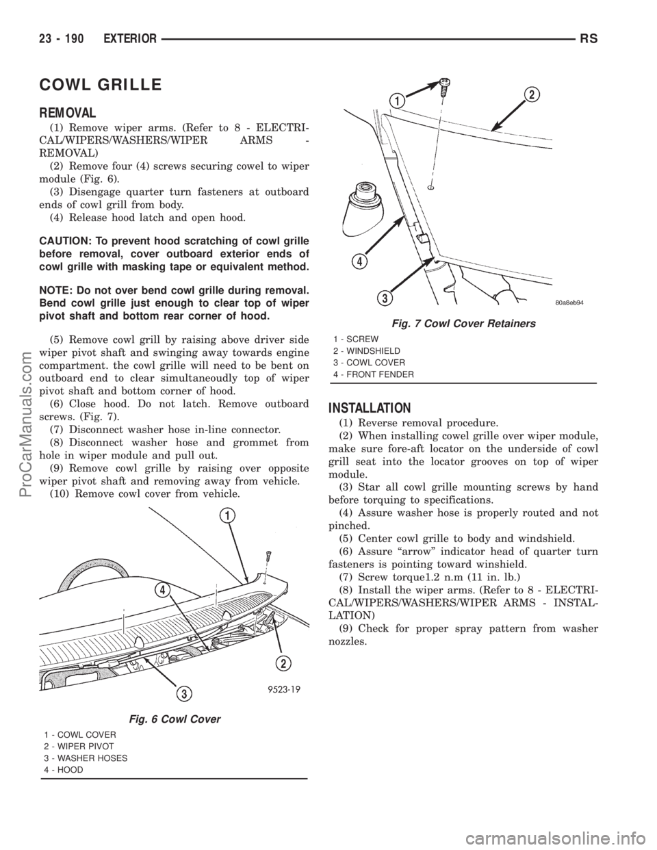
(2) Remove four (4) screws securing cowel to wiper
module (Fig. 6).
(3) Disengage quarter turn fasteners at outboard
ends of cowl grill from body.
(4) Release hood latch and open hood.
CAUTION: To prevent hood scratching of cowl grille
before removal, cover outboard exterior ends of
cowl grille with masking tape or equivalent method.
NOTE: Do not over bend cowl grille during removal.
Bend cowl grille just enough to clear top of wiper
pivot shaft and bottom rear corner of hood.
(5) Remove cowl grill by raising above driver side
wiper pivot shaft and swinging away towards engine
compartment. the cowl grille will need to be bent on
outboard end to clear simultaneoudly top of wiper
pivot shaft and bottom corner of hood.
(6) Close hood. Do not latch. Remove outboard
screws. (Fig. 7).
(7) Disconnect washer hose in-line connector.
(8) Disconnect washer hose and grommet from
hole in wiper module and pull out.
(9) Remove cowl grille by raising over opposite
wiper pivot shaft and removing away from vehicle.
(10) Remove cowl cover from vehicle.
INSTALLATION
(1) Reverse removal procedure.
(2) When installing cowel grille over wiper module,
make sure fore-aft locator on the underside of cowl
grill seat into the locator grooves on top of wiper
module.
(3) Star all cowl grille mounting screws by hand
before torquing to specifications.
(4) Assure washer hose is properly routed and not
pinched.
(5) Center cowl grille to body and windshield.
(6) Assure ªarrowº indicator head of quarter turn
fasteners is pointing toward winshield.
(7) Screw torque1.2 n.m (11 in. lb.)
(8) Install the wiper arms. (Refer to 8 - ELECTRI-
CAL/WIPERS/WASHERS/WIPER ARMS - INSTAL-
LATION)
(9) Check for proper spray pattern from washer
nozzles.
Fig. 6 Cowl Cover
1 - COWL COVER
2 - WIPER PIVOT
3 - WASHER HOSES
4 - HOOD
Fig. 7 Cowl Cover Retainers
1 - SCREW
2 - WINDSHIELD
3 - COWL COVER
4 - FRONT FENDER
23 - 190 EXTERIORRS
ProCarManuals.com
Page 2104 of 2321
EXTERIOR NAME PLATES -
TAPE ATTACHED
REMOVAL
(1) Mark reference points before removing.
(2) Using a heat gun gently apply heat in a circu-
lar motion to loosen the adhesive bond.
(3) Using a nonmetallic prying device, such as a
plastic or wood trim stick gently pry up at corners
and remove.
(4) Clean off all traces of adhesive or double sided
tape from the panel with a general purpose adhesive
remover.
INSTALLATION
(1) Clean panel surface with isopropy alcohol.
(2) Align badgeing to reference points.
(3) Install and press securely to full adhesive con-
tact
(4) Clean away any reference points.
EXTERIOR NAME PLATES -
ADHESIVE ATTACHED
REMOVAL
(1) Mark reference points before removing.
(2) Using a heat gun gently apply heat in a circu-
lar motion to loosen the adhesive bond.
(3) With your fingernail lift up and peel away
badgeing/tape from panel, using a heat gun as you
go.
(4) Clean off all traces of adhesive from the pan-
el(s) with a general purpose adhesive remover.
INSTALLATION
(1) Clean panel surface with isopropy alcohol.
(2) Remove paper carrier and align badgeing/tape
to reference points or adjacent panel.
(3) Install and press securely, using a plastic
spreader to eliminate all air bubbles.
(4) Remove top protective carrier.
(5) Clean away any reference points.
FRONT FENDER
REMOVAL
(1) Remove headlamp housing. (Refer to 8 - ELEC-
TRICAL/LAMPS/LIGHTING - EXTERIOR/HEAD-
LAMP UNIT - REMOVAL)
(2) Remove mud guard.
(3) Remove inner splash shield.
(4) Remove fender to fascia nuts.(5) Remove outboard cowl grille/fender bracket
screw.
(6) Remove fender bolt to lower rocker panel.
(7) Remove fender bolt to lower cowl.
(8) Pull fascia away from fender.
(9) Remove bolts attaching fender to upper rail.
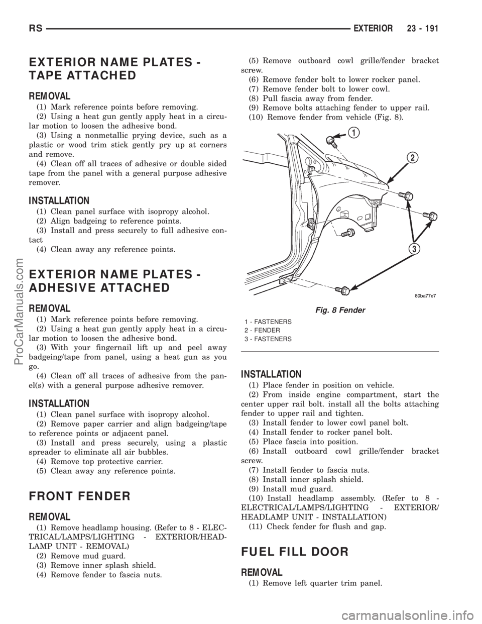
(10) Remove fender from vehicle (Fig. 8).
INSTALLATION
(1) Place fender in position on vehicle.
(2) From inside engine compartment, start the
center upper rail bolt. install all the bolts attaching
fender to upper rail and tighten.
(3) Install fender to lower cowl panel bolt.
(4) Install fender to rocker panel bolt.
(5) Place fascia into position.
(6) Install outboard cowl grille/fender bracket
screw.
(7) Install fender to fascia nuts.
(8) Install inner splash shield.
(9) Install mud guard.
(10) Install headlamp assembly. (Refer to 8 -
ELECTRICAL/LAMPS/LIGHTING - EXTERIOR/
HEADLAMP UNIT - INSTALLATION)
(11) Check fender for flush and gap.
FUEL FILL DOOR
REMOVAL
(1) Remove left quarter trim panel.
Fig. 8 Fender
1 - FASTENERS
2 - FENDER
3 - FASTENERS
RSEXTERIOR23 - 191
ProCarManuals.com
Page 2168 of 2321
MANUAL TEMPERATURE CONTROL
The front blower speed must be set to High and
the evaporator temperature sensor must be greater
than 55É F or the test will fail immediately. The test
is activated by depressing the A/C and PWR buttons
simultaneously and holding them depressed for no
less than five seconds. The PWR and A/C LEDs will
blink on and off until the test is complete. If the
LEDs stop blinking after two minutes, then the cool
down test has been completed successfully. If the two
minutes expire without the evaporator temperature
reaching 20É F less than the outside air temperature,
then the cool down test has been failed and further
A/C system diagnosis is required. If the test is failed,
the LEDs will continue to blink across ignition cycles
until the vehicle has been driven for greater than (3
miles).
AUTOMATIC TEMPERATURE CONTROL
The outside air temperature shown in the ATC dis-
play must not be lower than 53É F or the test will not
begin. The ambient air temperature in the room
where the vehicle will be tested must be a minimum
of 21É C (70ÉF) for this test.The test is activated by
depressing the A/C and PWR buttons simultaneously
and holding them depressed for no less than four sec-
onds. The snowflake icon and the DELAY text in the
ATC display will blink on and off alternately until
the test is complete. If the snowflake icon and the
DELAY text stop blinking after two minutes, then
the cool down test has been completed successfully. If
the two minutes expire without the evaporator tem-
perature reaching 20É F less than the evaporator ini-
tial temperature, then the cool down test has been
failed and further A/C system diagnosis is required.
If the test is failed, the snowflake icon and the
DELAY text will continue to blink across ignition
cycles until the vehicle has been driven for greater
than (3 miles).
DIAGNOSIS AND TESTING - A/C
PERFORMANCE TEST
An air conditioning performance test is the best
way to determine whether the system is performing
up to standard. This test also provides valuable clues
as to the possible cause of trouble with the air con-
ditioning system. The ambient air temperature in the
location where the vehicle will be tested must be a
minimum of 21É C (70ÉF) for this test.
WARNING: REFER TO THE APPLICABLE WARN-
INGS AND CAUTIONS FOR THIS SYSTEM BEFORE
PERFORMING THE FOLLOWING OPERATION.(Refer to 24 - HEATING & AIR CONDITIONING/
PLUMBING - FRONT - WARNING - A/C PLUMBING)
and (Refer to 24 - HEATING & AIR CONDITIONING/
PLUMBING - FRONT - CAUTION - A/C PLUMBING).
NOTE: When connecting the service equipment
coupling to the line fitting, verify that the valve of
the coupling is fully closed. This will reduce the
amount of effort required to make the connection.
(1) Connect a tachometer to monitor the engine
speed.
(2) Remove the caps from the refrigerant system
service ports and attach a manifold gauge set to
monitor the refrigerant system pressures.
(3) Set the heater-air conditioner controls so that
the compressor is engaged, the air within the vehicle
is being recirculated, the output air is directed
through the panel outlets, the temperature control is
in the full cool position, and the blower motor is oper-
ating at its highest speed.
(4) Start the engine and allow the engine to oper-
ate for about five minutes or until it reaches normal
operating temperature. Then hold the engine speed
at 1000 rpm with the compressor clutch engaged. If
the compressor clutch does not engage, proceed with
diagnosis of the compressor clutch coil. (Refer to 24 -
HEATING & AIR CONDITIONING/CONTROLS -
FRONT/COMPRESSOR CLUTCH COIL - DIAGNO-
SIS AND TESTING).
(5) Close all the vehicle windows and doors.
(6) Insert a thermometer in the left center panel
outlet and operate the engine for five minutes.
(7) With the compressor clutch engaged, record the
left center panel outlet discharge air temperature,
the discharge pressure (high side service port), and
the suction pressure (low side service port). The com-
pressor clutch may cycle, depending upon the ambi-
ent temperature and humidity. If the clutch cycles,
use the readings obtained before the clutch disen-
gaged.
(8) Compare the discharge air temperature read-
ing to the Performance Temperature and Pressure
chart. If the temperature reading is high, check the
refrigerant system for leaks and proper refrigerant
charge level. (Refer to 24 - HEATING & AIR CONDI-
TIONING/PLUMBING - FRONT/REFRIGERANT -
DIAGNOSIS AND TESTING - REFRIGERANT SYS-
TEM LEAKS) and (Refer to 24 - HEATING & AIR
CONDITIONING/PLUMBING - FRONT/REFRIGER-
ANT - DIAGNOSIS AND TESTING - REFRIGER-
ANT SYSTEM CHARGE LEVEL).
RSHEATING & AIR CONDITIONING24-5
HEATING & AIR CONDITIONING (Continued)
ProCarManuals.com
Page 2169 of 2321
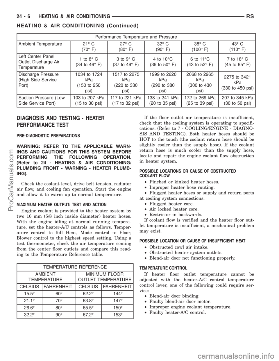
Performance Temperature and Pressure
Ambient Temperature 21É C
(70É F)27É C
(80É F)32É C
(90É F)38É C
(100É F)43É C
(110É F)
Left Center Panel
Outlet Discharge Air
Temperature1to8ÉC
(34 to 46É F)3to9ÉC
(37 to 49É F)4 to 10ÉC
(39 to 50É F)6to11ÉC
(43 to 52É F)7 to 18É C
(45 to 65É F)
Discharge Pressure
(High Side Service
Port)1034 to 1724
kPa
(150 to 250
psi)1517 to 2275
kPa
(220 to 330
psi)1999 to 2620
kPa
(290 to 380
psi)2068 to 2965
kPa
(300 to 430
psi)2275 to 3421
kPa
(330 to 450 psi)
Suction Pressure (Low
Side Service Port)103 to 207 kPa
(15 to 30 psi)117 to 221 kPa
(17 to 32 psi)138 to 241 kPa
(20 to 35 psi)172 to 269 kPa
(25 to 39 psi)207 to 345 kPa
(30 to 50 psi)
DIAGNOSIS AND TESTING - HEATER
PERFORMANCE TEST
PRE-DIAGNOSTIC PREPARATIONS
WARNING: REFER TO THE APPLICABLE WARN-
INGS AND CAUTIONS FOR THIS SYSTEM BEFORE
PERFORMING THE FOLLOWING OPERATION.
(Refer to 24 - HEATING & AIR CONDITIONING/
PLUMBING FRONT - WARNING - HEATER PLUMB-
ING).
Check the coolant level, drive belt tension, radiator
air flow, and cooling fan operation. Start the engine
and allow it to warm up to normal temperature.
MAXIMUM HEATER OUTPUT: TEST AND ACTION
Engine coolant is provided to the heater system by
two 16 mm (5/8 inch inside diameter) heater hoses.
With the engine idling at normal running tempera-
ture, set the heater-A/C controls as follows. Temper-
ature control to full Heat, Mode control to Floor,
Blower control to the highest speed setting. Using a
test thermometer, check the air temperature coming
from the center floor outlets and compare this read-
ing to the Temperature Reference table.
TEMPERATURE REFERENCE
AMBIENT
TEMPERATUREMINIMUM FLOOR
OUTLET TEMPERATURE
CELSIUS FAHRENHEIT CELSIUS FAHRENHEIT
15.5É 60É 62.2É 144É
21.1É 70É 63.8É 147É
26.6É 80É 65.5É 150É
32.2É 90É 67.2É 153ÉIf the floor outlet air temperature is insufficient,
check that the cooling system is operating to specifi-
cations. (Refer to 7 - COOLING/ENGINE - DIAGNO-
SIS AND TESTING). Both heater hoses should be
HOT to the touch (the coolant return hose should be
slightly cooler than the supply hose). If the coolant
return hose is much cooler than the supply hose,
locate and repair the engine coolant flow obstruction
in heater system.
POSSIBLE LOCATIONS OR CAUSE OF OBSTRUCTED
COOLANT FLOW
²Pinched or kinked heater hoses.
²Improper heater hose routing.
²Plugged heater hoses or supply and return ports
at cooling system connections.
²Plugged heater core.
²Air locked heater core.
²Restrictor in backwards.
If coolant flow is verified and the heater floor out-
let temperature is insufficient, a mechanical problem
may exist.
POSSIBLE LOCATION OR CAUSE OF INSUFFICIENT HEAT
²Obstructed cowl air intake.
²Obstructed heater system outlets.
²Blend-air door not functioning properly.
TEMPERATURE CONTROL
If heater floor outlet temperature cannot be
adjusted with the heater-A/C control temperature
control lever, one of the following could require ser-
vice:
²Blend-air door binding.
²Faulty blend-air door motor.
²Improper engine coolant temperature.
²Faulty heater-A/C control.
24 - 6 HEATING & AIR CONDITIONINGRS
HEATING & AIR CONDITIONING (Continued)
ProCarManuals.com