2001 DODGE TOWN AND COUNTRY oil dipstick
[x] Cancel search: oil dipstickPage 1291 of 2321
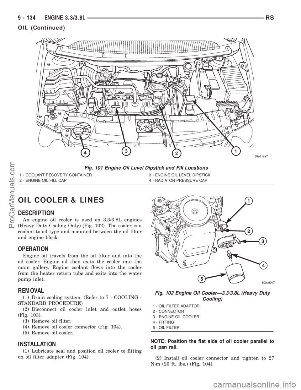
OIL COOLER & LINES
DESCRIPTION
An engine oil cooler is used on 3.3/3.8L engines
(Heavy Duty Cooling Only) (Fig. 102). The cooler is a
coolant-to-oil type and mounted between the oil filter
and engine block.
OPERATION
Engine oil travels from the oil filter and into the
oil cooler. Engine oil then exits the cooler into the
main gallery. Engine coolant flows into the cooler
from the heater return tube and exits into the water
pump inlet.
REMOVAL
(1) Drain cooling system. (Refer to 7 - COOLING -
STANDARD PROCEDURE)
(2) Disconnect oil cooler inlet and outlet hoses
(Fig. 103).
(3) Remove oil filter.
(4) Remove oil cooler connector (Fig. 104).
(5) Remove oil cooler.
INSTALLATION
(1) Lubricate seal and position oil cooler to fitting
on oil filter adapter (Fig. 104).NOTE: Position the flat side of oil cooler parallel to
oil pan rail.
(2) Install oil cooler connector and tighten to 27
N´m (20 ft. lbs.) (Fig. 104).
Fig. 101 Engine Oil Level Dipstick and Fill Locations
1 - COOLANT RECOVERY CONTAINER 3 - ENGINE OIL LEVEL DIPSTICK
2 - ENGINE OIL FILL CAP 4 - RADIATOR PRESSURE CAP
Fig. 102 Engine Oil CoolerÐ3.3/3.8L (Heavy Duty
Cooling)
1 - OIL FILTER ADAPTOR
2 - CONNECTOR
3 - ENGINE OIL COOLER
4 - FITTING
5 - OIL FILTER
9 - 134 ENGINE 3.3/3.8LRS
OIL (Continued)
ProCarManuals.com
Page 1293 of 2321
OIL PAN
REMOVAL
(1) Disconnect negative cable from battery and
remove engine oil dipstick.
(2) Raise vehicle on hoist and drain engine oil.
(3) Remove drive belt splash shield.
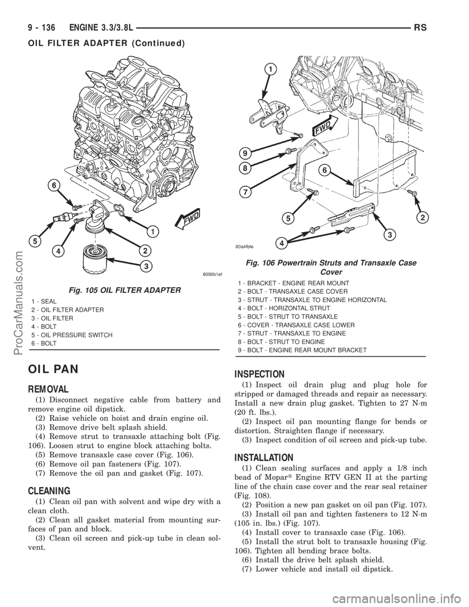
(4) Remove strut to transaxle attaching bolt (Fig.
106). Loosen strut to engine block attaching bolts.
(5) Remove transaxle case cover (Fig. 106).
(6) Remove oil pan fasteners (Fig. 107).
(7) Remove the oil pan and gasket (Fig. 107).
CLEANING
(1) Clean oil pan with solvent and wipe dry with a
clean cloth.
(2) Clean all gasket material from mounting sur-
faces of pan and block.
(3) Clean oil screen and pick-up tube in clean sol-
vent.
INSPECTION
(1) Inspect oil drain plug and plug hole for
stripped or damaged threads and repair as necessary.
Install a new drain plug gasket. Tighten to 27 N´m
(20 ft. lbs.).
(2) Inspect oil pan mounting flange for bends or
distortion. Straighten flange if necessary.
(3) Inspect condition of oil screen and pick-up tube.
INSTALLATION
(1) Clean sealing surfaces and apply a 1/8 inch
bead of MopartEngine RTV GEN II at the parting
line of the chain case cover and the rear seal retainer
(Fig. 108).
(2) Position a new pan gasket on oil pan (Fig. 107).
(3) Install oil pan and tighten fasteners to 12 N´m
(105 in. lbs.) (Fig. 107).
(4) Install cover to transaxle case (Fig. 106).
(5) Install the strut bolt to transaxle housing (Fig.
106). Tighten all bending brace bolts.
(6) Install the drive belt splash shield.
(7) Lower vehicle and install oil dipstick.
Fig. 105 OIL FILTER ADAPTER
1 - SEAL
2 - OIL FILTER ADAPTER
3 - OIL FILTER
4 - BOLT
5 - OIL PRESSURE SWITCH
6 - BOLT
Fig. 106 Powertrain Struts and Transaxle Case
Cover
1 - BRACKET - ENGINE REAR MOUNT
2 - BOLT - TRANSAXLE CASE COVER
3 - STRUT - TRANSAXLE TO ENGINE HORIZONTAL
4 - BOLT - HORIZONTAL STRUT
5 - BOLT - STRUT TO TRANSAXLE
6 - COVER - TRANSAXLE CASE LOWER
7 - STRUT - TRANSAXLE TO ENGINE
8 - BOLT - STRUT TO ENGINE
9 - BOLT - ENGINE REAR MOUNT BRACKET
9 - 136 ENGINE 3.3/3.8LRS
OIL FILTER ADAPTER (Continued)
ProCarManuals.com
Page 1340 of 2321
(7) Remove power steering belt (Refer to 7 -
COOLING/ACCESSORY DRIVE/DRIVE BELTS -
REMOVAL).
(8) Remove accessory drive belt (Refer to 7 -
COOLING/ACCESSORY DRIVE/DRIVE BELTS -
REMOVAL).
(9) Remove generator (Refer to 8 - ELECTRICAL/
CHARGING/GENERATOR - REMOVAL).
(10) Support engine and remove right engine
mount (Refer to 9 - ENGINE/ENGINE MOUNTING/
RIGHT MOUNT - REMOVAL).
(11) Remove outer timing belt cover (Refer to 9 -
ENGINE/VALVE TIMING/TIMING BELT / CHAIN
COVER(S) - REMOVAL).
(12) Remove timing belt (Refer to 9 - ENGINE/
VALVE TIMING/TIMING BELT/CHAIN AND
SPROCKETS - REMOVAL).
(13) Remove inner timing belt cover (Refer to 9 -
ENGINE/VALVE TIMING/TIMING BELT / CHAIN
COVER(S) - REMOVAL).
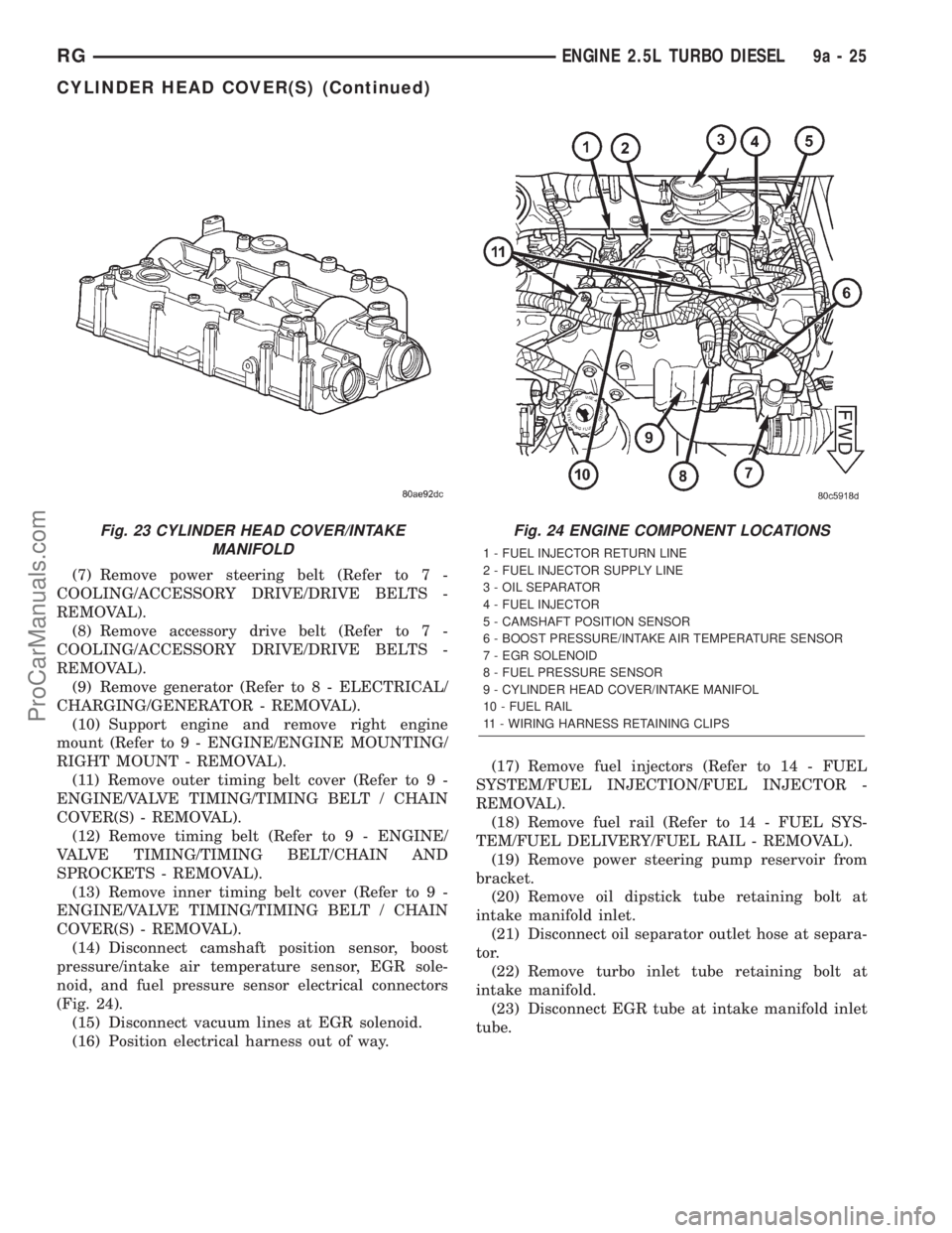
(14) Disconnect camshaft position sensor, boost
pressure/intake air temperature sensor, EGR sole-
noid, and fuel pressure sensor electrical connectors
(Fig. 24).
(15) Disconnect vacuum lines at EGR solenoid.
(16) Position electrical harness out of way.(17) Remove fuel injectors (Refer to 14 - FUEL
SYSTEM/FUEL INJECTION/FUEL INJECTOR -
REMOVAL).
(18) Remove fuel rail (Refer to 14 - FUEL SYS-
TEM/FUEL DELIVERY/FUEL RAIL - REMOVAL).
(19) Remove power steering pump reservoir from
bracket.
(20) Remove oil dipstick tube retaining bolt at
intake manifold inlet.
(21) Disconnect oil separator outlet hose at separa-
tor.
(22) Remove turbo inlet tube retaining bolt at
intake manifold.
(23) Disconnect EGR tube at intake manifold inlet
tube.
Fig. 23 CYLINDER HEAD COVER/INTAKE
MANIFOLDFig. 24 ENGINE COMPONENT LOCATIONS
1 - FUEL INJECTOR RETURN LINE
2 - FUEL INJECTOR SUPPLY LINE
3 - OIL SEPARATOR
4 - FUEL INJECTOR
5 - CAMSHAFT POSITION SENSOR
6 - BOOST PRESSURE/INTAKE AIR TEMPERATURE SENSOR
7 - EGR SOLENOID
8 - FUEL PRESSURE SENSOR
9 - CYLINDER HEAD COVER/INTAKE MANIFOL
10 - FUEL RAIL
11 - WIRING HARNESS RETAINING CLIPS
RGENGINE 2.5L TURBO DIESEL9a-25
CYLINDER HEAD COVER(S) (Continued)
ProCarManuals.com
Page 1342 of 2321
(4) Install turbo inlet tube retaining bolt at intake
manifold. Torque bolt to 27.5 N´m.
(5) Connect oil separator outlet hose at separator.
(6) Install oil dipstick tube retaining bolt at intake
manifold inlet. Torque bolt to 10 N´m.
(7) Install power steering pump reservoir in
bracket.
(8) Install fuel rail (Refer to 14 - FUEL SYSTEM/
FUEL DELIVERY/FUEL RAIL - INSTALLATION).
(9) Install fuel injectors and fuel injector supply
lines (Refer to 14 - FUEL SYSTEM/FUEL INJEC-
TION/FUEL INJECTOR - INSTALLATION).
(10) Connect vacuum lines at EGR solenoid.
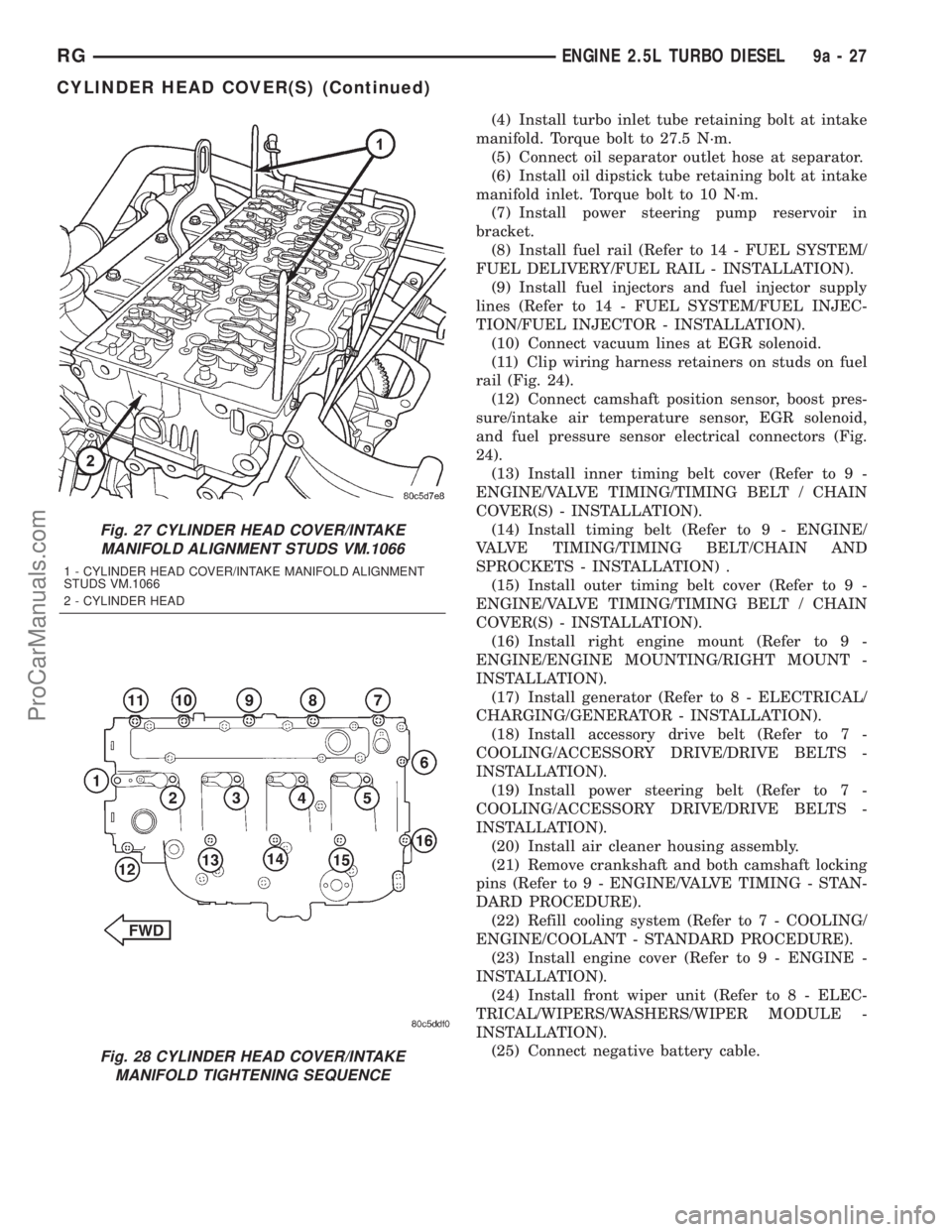
(11) Clip wiring harness retainers on studs on fuel
rail (Fig. 24).
(12) Connect camshaft position sensor, boost pres-
sure/intake air temperature sensor, EGR solenoid,
and fuel pressure sensor electrical connectors (Fig.
24).
(13) Install inner timing belt cover (Refer to 9 -
ENGINE/VALVE TIMING/TIMING BELT / CHAIN
COVER(S) - INSTALLATION).
(14) Install timing belt (Refer to 9 - ENGINE/
VALVE TIMING/TIMING BELT/CHAIN AND
SPROCKETS - INSTALLATION) .
(15) Install outer timing belt cover (Refer to 9 -
ENGINE/VALVE TIMING/TIMING BELT / CHAIN
COVER(S) - INSTALLATION).
(16) Install right engine mount (Refer to 9 -
ENGINE/ENGINE MOUNTING/RIGHT MOUNT -
INSTALLATION).
(17) Install generator (Refer to 8 - ELECTRICAL/
CHARGING/GENERATOR - INSTALLATION).
(18) Install accessory drive belt (Refer to 7 -
COOLING/ACCESSORY DRIVE/DRIVE BELTS -
INSTALLATION).
(19) Install power steering belt (Refer to 7 -
COOLING/ACCESSORY DRIVE/DRIVE BELTS -
INSTALLATION).
(20) Install air cleaner housing assembly.
(21) Remove crankshaft and both camshaft locking
pins (Refer to 9 - ENGINE/VALVE TIMING - STAN-
DARD PROCEDURE).
(22) Refill cooling system (Refer to 7 - COOLING/
ENGINE/COOLANT - STANDARD PROCEDURE).
(23) Install engine cover (Refer to 9 - ENGINE -
INSTALLATION).
(24) Install front wiper unit (Refer to 8 - ELEC-
TRICAL/WIPERS/WASHERS/WIPER MODULE -
INSTALLATION).
(25) Connect negative battery cable.
Fig. 27 CYLINDER HEAD COVER/INTAKE
MANIFOLD ALIGNMENT STUDS VM.1066
1 - CYLINDER HEAD COVER/INTAKE MANIFOLD ALIGNMENT
STUDS VM.1066
2 - CYLINDER HEAD
Fig. 28 CYLINDER HEAD COVER/INTAKE
MANIFOLD TIGHTENING SEQUENCE
RGENGINE 2.5L TURBO DIESEL9a-27
CYLINDER HEAD COVER(S) (Continued)
ProCarManuals.com
Page 1364 of 2321
(7) Install timing belt (Refer to 9 - ENGINE/
VALVE TIMING/TIMING BELT/CHAIN AND
SPROCKETS - INSTALLATION) .
(8) Install timing belt outer cover (Refer to 9 -
ENGINE/VALVE TIMING/TIMING BELT / CHAIN
COVER(S) - INSTALLATION).
(9) Install accessory drive belt (Refer to 7 - COOL-
ING/ACCESSORY DRIVE/DRIVE BELTS - INSTAL-
LATION).
(10) Install power steering belt (Refer to 7 -
COOLING/ACCESSORY DRIVE/DRIVE BELTS -
INSTALLATION).
(11) Connect negative battery cable.
INSTALLATION
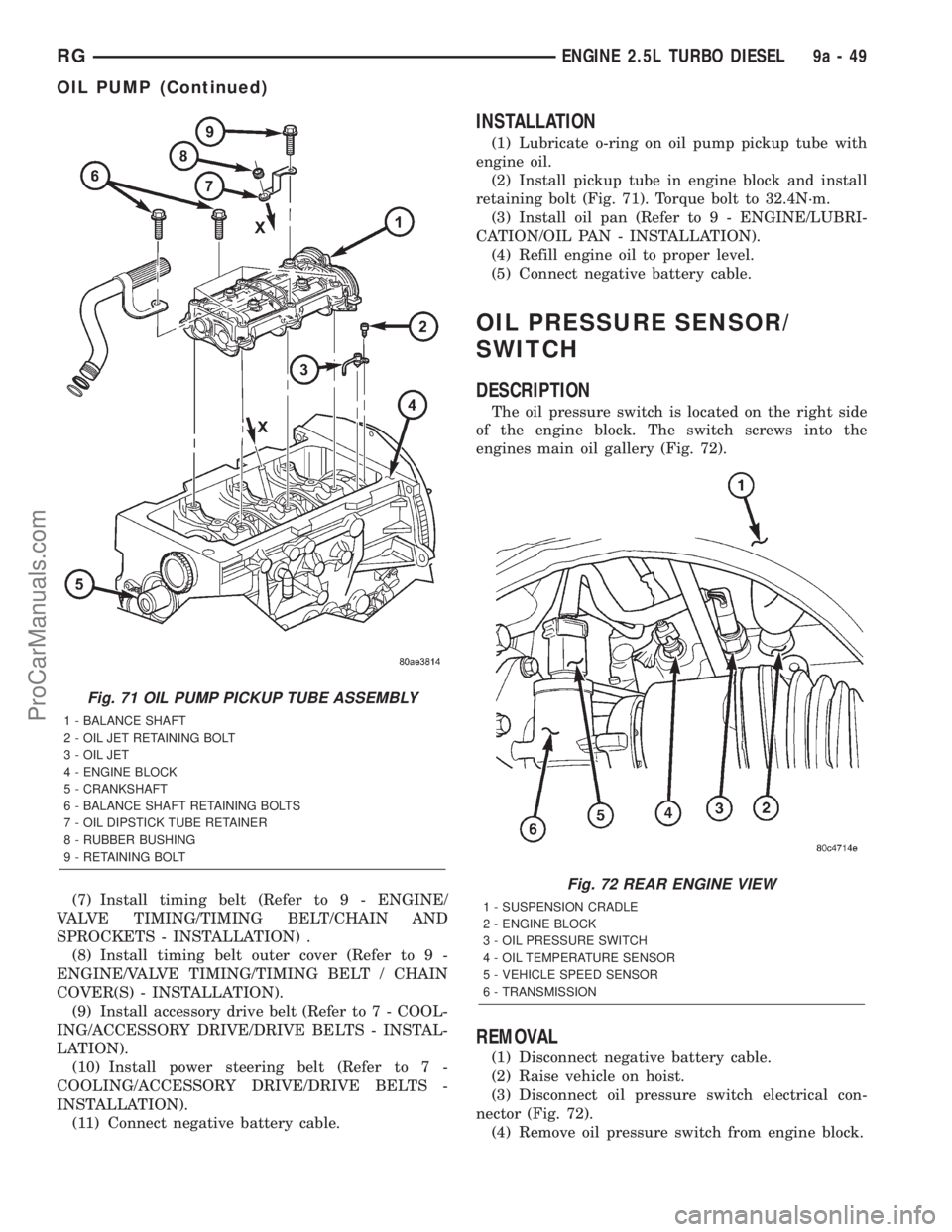
(1) Lubricate o-ring on oil pump pickup tube with
engine oil.
(2) Install pickup tube in engine block and install
retaining bolt (Fig. 71). Torque bolt to 32.4N´m.
(3) Install oil pan (Refer to 9 - ENGINE/LUBRI-
CATION/OIL PAN - INSTALLATION).
(4) Refill engine oil to proper level.
(5) Connect negative battery cable.
OIL PRESSURE SENSOR/
SWITCH
DESCRIPTION
The oil pressure switch is located on the right side
of the engine block. The switch screws into the
engines main oil gallery (Fig. 72).
REMOVAL
(1) Disconnect negative battery cable.
(2) Raise vehicle on hoist.
(3) Disconnect oil pressure switch electrical con-
nector (Fig. 72).
(4) Remove oil pressure switch from engine block.
Fig. 71 OIL PUMP PICKUP TUBE ASSEMBLY
1 - BALANCE SHAFT
2 - OIL JET RETAINING BOLT
3 - OIL JET
4 - ENGINE BLOCK
5 - CRANKSHAFT
6 - BALANCE SHAFT RETAINING BOLTS
7 - OIL DIPSTICK TUBE RETAINER
8 - RUBBER BUSHING
9 - RETAINING BOLT
Fig. 72 REAR ENGINE VIEW
1 - SUSPENSION CRADLE
2 - ENGINE BLOCK
3 - OIL PRESSURE SWITCH
4 - OIL TEMPERATURE SENSOR
5 - VEHICLE SPEED SENSOR
6 - TRANSMISSION
RGENGINE 2.5L TURBO DIESEL9a-49
OIL PUMP (Continued)
ProCarManuals.com
Page 1371 of 2321
OPERATION
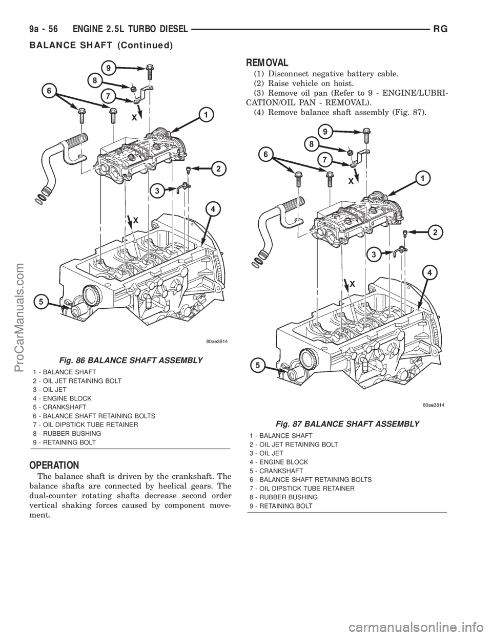
The balance shaft is driven by the crankshaft. The
balance shafts are connected by heelical gears. The
dual-counter rotating shafts decrease second order
vertical shaking forces caused by component move-
ment.
REMOVAL
(1) Disconnect negative battery cable.
(2) Raise vehicle on hoist.
(3) Remove oil pan (Refer to 9 - ENGINE/LUBRI-
CATION/OIL PAN - REMOVAL).
(4) Remove balance shaft assembly (Fig. 87).
Fig. 86 BALANCE SHAFT ASSEMBLY
1 - BALANCE SHAFT
2 - OIL JET RETAINING BOLT
3 - OIL JET
4 - ENGINE BLOCK
5 - CRANKSHAFT
6 - BALANCE SHAFT RETAINING BOLTS
7 - OIL DIPSTICK TUBE RETAINER
8 - RUBBER BUSHING
9 - RETAINING BOLT
Fig. 87 BALANCE SHAFT ASSEMBLY
1 - BALANCE SHAFT
2 - OIL JET RETAINING BOLT
3 - OIL JET
4 - ENGINE BLOCK
5 - CRANKSHAFT
6 - BALANCE SHAFT RETAINING BOLTS
7 - OIL DIPSTICK TUBE RETAINER
8 - RUBBER BUSHING
9 - RETAINING BOLT
9a - 56 ENGINE 2.5L TURBO DIESELRG
BALANCE SHAFT (Continued)
ProCarManuals.com
Page 1519 of 2321
REMOVAL.............................118
INSTALLATION..........................118
THROTTLE VALVE CABLE
REMOVAL.............................118
INSTALLATION..........................118
ADJUSTMENTS.........................120
TORQUE CONVERTER
DESCRIPTION..........................120
OPERATION............................123
REMOVAL.............................125
INSTALLATION..........................125
TRANSFER SYSTEM - OUTPUT SHAFT/GEAR/
BEARING
REMOVAL.............................126
INSTALLATION..........................129
ADJUSTMENTS.........................132TRANSFER SYSTEM - TRANSFER SHAFT/
GEAR/BEARING
REMOVAL.............................134
INSTALLATION..........................137
ADJUSTMENTS.........................142
VALVE BODY
REMOVAL.............................142
DISASSEMBLY..........................145
CLEANING.............................151
INSPECTION...........................152
ASSEMBLY............................152
INSTALLATION..........................155
ADJUSTMENTS.........................157
VEHICLE SPEED SENSOR/PINION GEAR
REMOVAL.............................157
INSTALLATION..........................157
AUTOMATIC - 31TH
DESCRIPTION
This transaxle combines torque converter, three
speed transmission, final drive gearing, and differen-
tial into a front wheel drive system.
Within this transaxle, there are three primary
areas:
(1) Main center line plus valve body.
(2) Transfer shaft center line (includes governor
and parking sprag).
(3) Differential center line.
Center distances between the main rotating parts
in these three areas are held precise to maintain a
low noise level.
The torque converter, transaxle area, and differen-
tial are housed in an integral aluminum die casting.
The differential oil sump is common with the
transaxle sump. Separate filling of the differen-
tial is NOT necessary.
The torque converter is attached to the crankshaft
through a flexible driving plate. Cooling of the con-
verter is accomplished by circulating the transaxle
fluid through a remote cooler. There are two types of
coolers used. An oil-to-water type cooler located in
the radiator side tank and/or an oil-to-air heat
exchanger. The torque converter assembly is a sealed
unit that cannot be disassembled.
The transaxle fluid is filtered by an internal filter
attached to the lower side of the valve body assembly.Engine torque is transmitted to the torque con-
verter and then through the input shaft to multiple-
disc clutches in the transaxle. The power flow
depends on the application of the clutches and bands.
Refer to Elements in Use Chart in Diagnosis and
Tests section.
The transaxle consists of:
²Two multiple-disc clutches
²An overrunning clutch
²Two servos
²A hydraulic accumulator
²Two bands
²Two planetary gear sets
This provides three forward ratios and a reverse
ratio. The common sun gear of the planetary gear
sets is connected to the front clutch by a driving
shell. The driving shell is splined to the sun gear and
front clutch retainer. The hydraulic system consists
of an oil pump and a single valve body which con-
tains all of the valves except the governor valves.
The transaxle sump and differential sump are both
vented through the dipstick. Output torque from the
main center line is delivered through helical gears to
the transfer shaft. This gear set is a factor in the
transaxle final drive (axle) ratio. The shaft also car-
ries the governor and parking sprag. An integral heli-
cal gear on the transfer shaft drives the differential
ring gear.
21 - 22 AUTOMATIC - 31THRS
ProCarManuals.com
Page 1523 of 2321
CONDITION POSSIBLE CAUSES CORRECTION
NO DRIVE OR
REVERSE (VEHICLE
WILL NOT MOVE)1. Fluid Level Low. 1. Add fluid and check for leaks if drive is
restored.
2. Gearshift Linkage/Cable Loose/
Misadjusted.2. Inspect, adjust and reassemble linkage
as needed. Replace worn/damaged parts.
3. Filter Plugged. 3. Remove and disassemble transmission.
Repair or replace failed components as
needed. Replace filter. If filter and fluid
contained clutch material or metal
particles, an overhaul may be necessary.
Perform lube flow test. Flush oil. Replace
cooler as necessary.
4. Oil Pump Damaged. 4. Perform pressure test to confirm low
pressure. Replace pump body assembly if
necessary.
5. Valve Body Malfunctioned. 5. Check press and inspect valve body.
Replace valve body (as assembly) if any
valve or bore is damaged. Clean and
reassemble correctly if all parts are in
good condition.
6. Transmission Internal Component
Damaged.6. Remove and disassemble transmission.
Repair or replace failed components as
needed. Remove and disassemble
transmission. Repair or replace failed
components as needed.
7. Park Sprag not Releasing - Check Stall
Speed, Worn/Damaged/Stuck.7. Remove, disassemble, repair.
8. Torque Converter Damage. 8. Inspect and replace as required.
SHIFTS DELAYED OR
ERRATIC (ALSO
SHIFTS HARSH AT
TIMES)1. Fluid Level Low/High. 1. Correct fluid level and check for leaks if
low.
2. Fluid Filter Clogged. 2. Replace filter. If filter and fluid
contained clutch material or metal
particles, an overhaul may be necessary.
Perform lube flow test.
3. Throttle Linkage Misadjusted. 3. Adjust linkage as described in service
section.
4. Throttle Linkage Binding. 4. Check cable for binding. Check for
return to closed throttle at transmission.
5. Gearshift Linkage/Cable Misadjusted. 5. Adjust linkage/cable as described in
service section.
6. Governor Valve Sticking. 6. Inspect, clean or repair.
7. Governor Seal Rings Worn/Damaged. 7. Inspect/replace.
8. Clutch or Servo Failure. 8. Remove valve body and air test clutch,
and band servo operation. Disassemble
and repair transmission as needed.
9. Front Band Misadjusted. 9. Adjust band.
10. Pump Suction Passage Leak. 10. Check for excessive foam on dipstick
after normal driving. Check for loose
pump bolts, defective gasket. Replace
pump assembly if needed.
21 - 26 AUTOMATIC - 31THRS
AUTOMATIC - 31TH (Continued)
ProCarManuals.com