2001 DODGE TOWN AND COUNTRY atf 4
[x] Cancel search: atf 4Page 25 of 2321
CONTAINER IDENTIFICATION
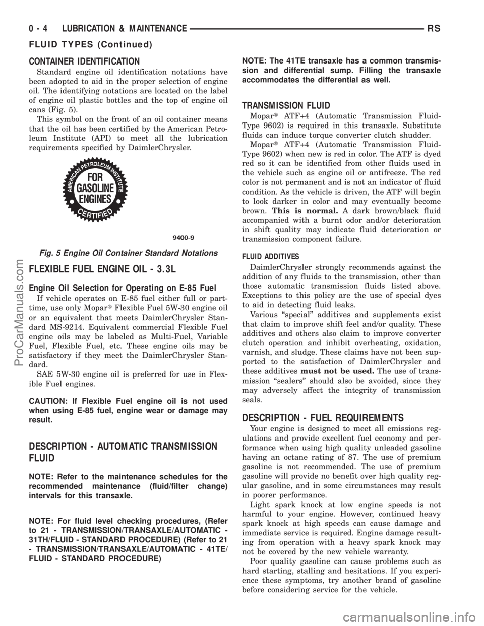
Standard engine oil identification notations have
been adopted to aid in the proper selection of engine
oil. The identifying notations are located on the label
of engine oil plastic bottles and the top of engine oil
cans (Fig. 5).
This symbol on the front of an oil container means
that the oil has been certified by the American Petro-
leum Institute (API) to meet all the lubrication
requirements specified by DaimlerChrysler.
FLEXIBLE FUEL ENGINE OIL - 3.3L
Engine Oil Selection for Operating on E-85 Fuel
If vehicle operates on E-85 fuel either full or part-
time, use only MopartFlexible Fuel 5W-30 engine oil
or an equivalent that meets DaimlerChrysler Stan-
dard MS-9214. Equivalent commercial Flexible Fuel
engine oils may be labeled as Multi-Fuel, Variable
Fuel, Flexible Fuel, etc. These engine oils may be
satisfactory if they meet the DaimlerChrysler Stan-
dard.
SAE 5W-30 engine oil is preferred for use in Flex-
ible Fuel engines.
CAUTION: If Flexible Fuel engine oil is not used
when using E-85 fuel, engine wear or damage may
result.
DESCRIPTION - AUTOMATIC TRANSMISSION
FLUID
NOTE: Refer to the maintenance schedules for the
recommended maintenance (fluid/filter change)
intervals for this transaxle.
NOTE: For fluid level checking procedures, (Refer
to 21 - TRANSMISSION/TRANSAXLE/AUTOMATIC -
31TH/FLUID - STANDARD PROCEDURE) (Refer to 21
- TRANSMISSION/TRANSAXLE/AUTOMATIC - 41TE/
FLUID - STANDARD PROCEDURE)NOTE: The 41TE transaxle has a common transmis-
sion and differential sump. Filling the transaxle
accommodates the differential as well.
TRANSMISSION FLUID
MopartATF+4 (Automatic Transmission Fluid-
Type 9602) is required in this transaxle. Substitute
fluids can induce torque converter clutch shudder.
MopartATF+4 (Automatic Transmission Fluid-
Type 9602) when new is red in color. The ATF is dyed
red so it can be identified from other fluids used in
the vehicle such as engine oil or antifreeze. The red
color is not permanent and is not an indicator of fluid
condition. As the vehicle is driven, the ATF will begin
to look darker in color and may eventually become
brown.This is normal.A dark brown/black fluid
accompanied with a burnt odor and/or deterioration
in shift quality may indicate fluid deterioration or
transmission component failure.
FLUID ADDITIVES
DaimlerChrysler strongly recommends against the
addition of any fluids to the transmission, other than
those automatic transmission fluids listed above.
Exceptions to this policy are the use of special dyes
to aid in detecting fluid leaks.
Various ªspecialº additives and supplements exist
that claim to improve shift feel and/or quality. These
additives and others also claim to improve converter
clutch operation and inhibit overheating, oxidation,
varnish, and sludge. These claims have not been sup-
ported to the satisfaction of DaimlerChrysler and
these additivesmust not be used.The use of trans-
mission ªsealersº should also be avoided, since they
may adversely affect the integrity of transmission
seals.
DESCRIPTION - FUEL REQUIREMENTS
Your engine is designed to meet all emissions reg-
ulations and provide excellent fuel economy and per-
formance when using high quality unleaded gasoline
having an octane rating of 87. The use of premium
gasoline is not recommended. The use of premium
gasoline will provide no benefit over high quality reg-
ular gasoline, and in some circumstances may result
in poorer performance.
Light spark knock at low engine speeds is not
harmful to your engine. However, continued heavy
spark knock at high speeds can cause damage and
immediate service is required. Engine damage result-
ing from operation with a heavy spark knock may
not be covered by the new vehicle warranty.
Poor quality gasoline can cause problems such as
hard starting, stalling and hesitations. If you experi-
ence these symptoms, try another brand of gasoline
before considering service for the vehicle.
Fig. 5 Engine Oil Container Standard Notations
0 - 4 LUBRICATION & MAINTENANCERS
FLUID TYPES (Continued)
ProCarManuals.com
Page 42 of 2321
LUBRICANTS AND GREASES
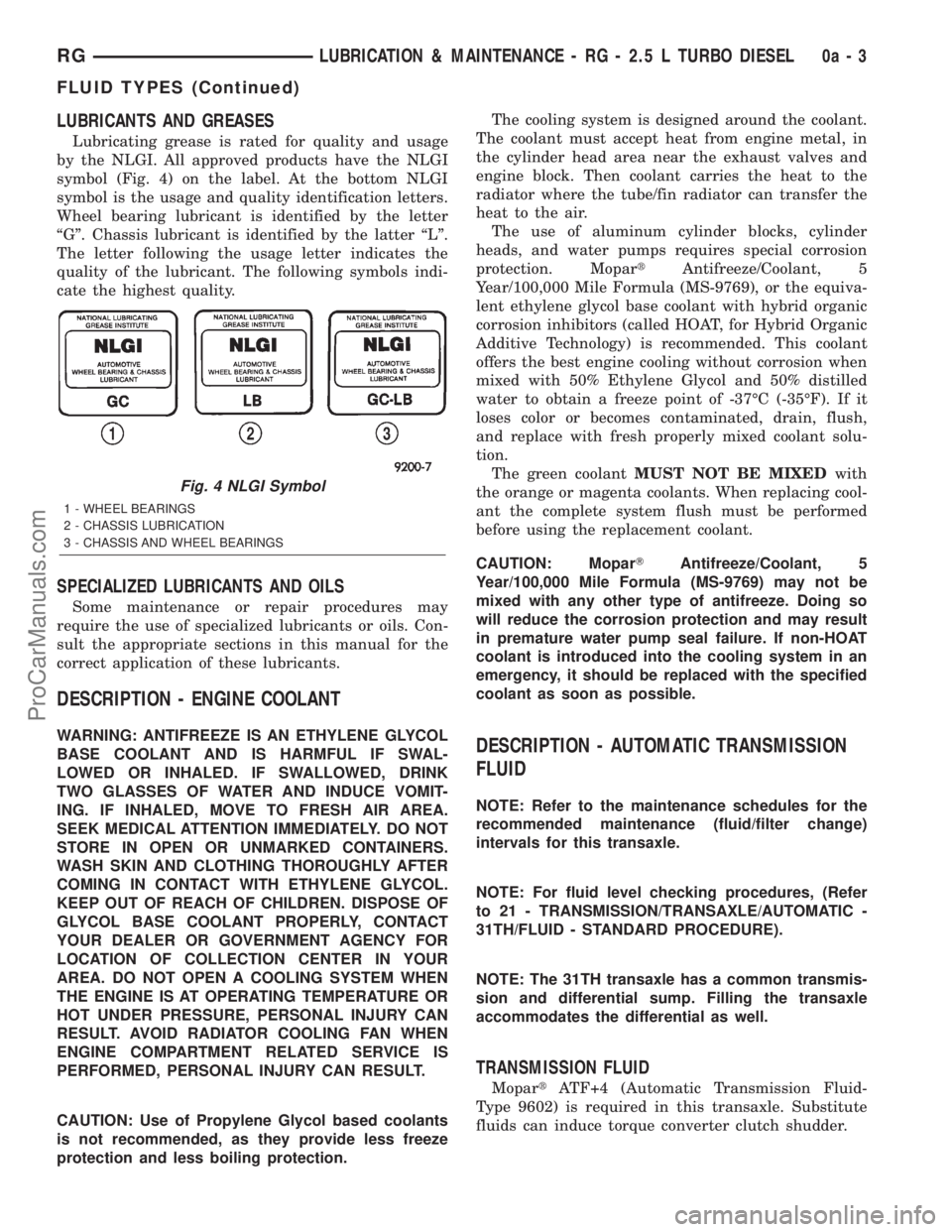
Lubricating grease is rated for quality and usage
by the NLGI. All approved products have the NLGI
symbol (Fig. 4) on the label. At the bottom NLGI
symbol is the usage and quality identification letters.
Wheel bearing lubricant is identified by the letter
ªGº. Chassis lubricant is identified by the latter ªLº.
The letter following the usage letter indicates the
quality of the lubricant. The following symbols indi-
cate the highest quality.
SPECIALIZED LUBRICANTS AND OILS
Some maintenance or repair procedures may
require the use of specialized lubricants or oils. Con-
sult the appropriate sections in this manual for the
correct application of these lubricants.
DESCRIPTION - ENGINE COOLANT
WARNING: ANTIFREEZE IS AN ETHYLENE GLYCOL
BASE COOLANT AND IS HARMFUL IF SWAL-
LOWED OR INHALED. IF SWALLOWED, DRINK
TWO GLASSES OF WATER AND INDUCE VOMIT-
ING. IF INHALED, MOVE TO FRESH AIR AREA.
SEEK MEDICAL ATTENTION IMMEDIATELY. DO NOT
STORE IN OPEN OR UNMARKED CONTAINERS.
WASH SKIN AND CLOTHING THOROUGHLY AFTER
COMING IN CONTACT WITH ETHYLENE GLYCOL.
KEEP OUT OF REACH OF CHILDREN. DISPOSE OF
GLYCOL BASE COOLANT PROPERLY, CONTACT
YOUR DEALER OR GOVERNMENT AGENCY FOR
LOCATION OF COLLECTION CENTER IN YOUR
AREA. DO NOT OPEN A COOLING SYSTEM WHEN
THE ENGINE IS AT OPERATING TEMPERATURE OR
HOT UNDER PRESSURE, PERSONAL INJURY CAN
RESULT. AVOID RADIATOR COOLING FAN WHEN
ENGINE COMPARTMENT RELATED SERVICE IS
PERFORMED, PERSONAL INJURY CAN RESULT.
CAUTION: Use of Propylene Glycol based coolants
is not recommended, as they provide less freeze
protection and less boiling protection.The cooling system is designed around the coolant.
The coolant must accept heat from engine metal, in
the cylinder head area near the exhaust valves and
engine block. Then coolant carries the heat to the
radiator where the tube/fin radiator can transfer the
heat to the air.
The use of aluminum cylinder blocks, cylinder
heads, and water pumps requires special corrosion
protection. MopartAntifreeze/Coolant, 5
Year/100,000 Mile Formula (MS-9769), or the equiva-
lent ethylene glycol base coolant with hybrid organic
corrosion inhibitors (called HOAT, for Hybrid Organic
Additive Technology) is recommended. This coolant
offers the best engine cooling without corrosion when
mixed with 50% Ethylene Glycol and 50% distilled
water to obtain a freeze point of -37ÉC (-35ÉF). If it
loses color or becomes contaminated, drain, flush,
and replace with fresh properly mixed coolant solu-
tion.
The green coolantMUST NOT BE MIXEDwith
the orange or magenta coolants. When replacing cool-
ant the complete system flush must be performed
before using the replacement coolant.
CAUTION: MoparTAntifreeze/Coolant, 5
Year/100,000 Mile Formula (MS-9769) may not be
mixed with any other type of antifreeze. Doing so
will reduce the corrosion protection and may result
in premature water pump seal failure. If non-HOAT
coolant is introduced into the cooling system in an
emergency, it should be replaced with the specified
coolant as soon as possible.DESCRIPTION - AUTOMATIC TRANSMISSION
FLUID
NOTE: Refer to the maintenance schedules for the
recommended maintenance (fluid/filter change)
intervals for this transaxle.
NOTE: For fluid level checking procedures, (Refer
to 21 - TRANSMISSION/TRANSAXLE/AUTOMATIC -
31TH/FLUID - STANDARD PROCEDURE).
NOTE: The 31TH transaxle has a common transmis-
sion and differential sump. Filling the transaxle
accommodates the differential as well.
TRANSMISSION FLUID
MopartATF+4 (Automatic Transmission Fluid-
Type 9602) is required in this transaxle. Substitute
fluids can induce torque converter clutch shudder.
Fig. 4 NLGI Symbol
1 - WHEEL BEARINGS
2 - CHASSIS LUBRICATION
3 - CHASSIS AND WHEEL BEARINGS
RGLUBRICATION & MAINTENANCE - RG - 2.5 L TURBO DIESEL0a-3
FLUID TYPES (Continued)
ProCarManuals.com
Page 43 of 2321

MopartATF+4 (Automatic Transmission Fluid-
Type 9602) when new is red in color. The ATF is dyed
red so it can be identified from other fluids used in
the vehicle such as engine oil or antifreeze. The red
color is not permanent and is not an indicator of fluid
condition. As the vehicle is driven, the ATF will begin
to look darker in color and may eventually become
brown.This is normal.A dark brown/black fluid
accompanied with a burnt odor and/or deterioration
in shift quality may indicate fluid deterioration or
transmission component failure.
FLUID ADDITIVES
DaimlerChrysler strongly recommends against the
addition of any fluids to the transmission, other than
those automatic transmission fluids listed above.
Exceptions to this policy are the use of special dyes
to aid in detecting fluid leaks.
Various ªspecialº additives and supplements exist
that claim to improve shift feel and/or quality. These
additives and others also claim to improve converter
clutch operation and inhibit overheating, oxidation,
varnish, and sludge. These claims have not been sup-
ported to the satisfaction of DaimlerChrysler and these
additivesmust not be used.
The use of transmission
ªsealersº should also be avoided, since they may
adversely affect the integrity of transmission seals.
DESCRIPTION - FUEL REQUIREMENTS -
DIESEL ENGINE
WARNING: DO NOT USE ALCOHOL OR GASOLINE
AS A FUEL BLENDING AGENT. THEY CAN BE
UNSTABLE UNDER CERTAIN CONDITIONS AND
HAZARDOUS OR EXPLOSIVE WHEN MIXED WITH
DIESEL FUEL.
Use good quality diesel fuel from a reputable sup-
plier. For most year-round service, number 2 diesel
fuel meeting ASTM specification D-975 will provide
good performance. If the vehicle is exposed to
extreme cold (below -18ÉC/0ÉF) or is required to oper-
ate at colder than normal conditions for prolonged
periods, use climatize No. 2 diesel fuel or dilute the
No. 2 diesel fuel with 50% No. 1 diesel fuel. This will
provide better protection from fuel gelling or wax
plugging of the fuel filters.
Diesel fuel is seldom completely free of water. To
prevent fuel system trouble, including fuel line freez-
ing in winter, drain the accumulated water from the
fuel/water separator using the fuel/water separator
drain provided. If you buy good quality fuel and follow
the cold weather advice above, fuel conditioners should
not be required in your vehicle. If available in your
area, a high cetane ªpremiumº diesel fuel may offer
improved cold starting and warm up performance.
DESCRIPTION - DIESEL ENGINE OIL
API SERVICE GRADE CERTIFIED
WARNING: NEW OR USED ENGINE OIL CAN BE
IRRITATING TO THE SKIN. AVOID PROLONGED OR
REPEATED SKIN CONTACT WITH ENGINE OIL.
CONTAMINANTS IN USED ENGINE OIL, CAUSED BY
INTERNAL COMBUSTION, CAN BE HAZARDOUS TO
YOUR HEALTH. THOROUGHLY WASH EXPOSED
SKIN WITH SOAP AND WATER. DO NOT WASH
SKIN WITH GASOLINE, DIESEL FUEL, THINNER, OR
SOLVENTS, HEALTH PROBLEMS CAN RESULT. DO
NOT POLLUTE, DISPOSE OF USED ENGINE OIL
PROPERLY. CONTACT YOUR DEALER OR GOVERN-
MENT AGENCY FOR LOCATION OF COLLECTION
CENTER IN YOUR AREA.
Standard engine oil identification notations have
been adopted to aid in the proper selection of engine
oil. The identifying notations are located on the label
of engine oil plastic bottles and the top of engine oil
cans.
In diesel engines, use an engine oil that conforms
to API Service Grade CF-4 or CG-4/SH (Fig. 5).
MOPARtprovides an engine oil that conforms to this
particular grade.
SAE VISCOSITY
An SAE viscosity grade is used to specify the vis-
cosity of engine oil. SAE 15W±40 specifies a multiple
viscosity engine oil.
When choosing an engine oil, consider the range of
temperatures the vehicle will be operated in before the
next oil change. Select an engine oil that is best suited
to your area's particular ambient temperature range
and variation. For diesel engines, refer to (Fig. 6).
Fig. 5 API Service Grade Certification LabelÐDiesel
Engine Oil
0a - 4 LUBRICATION & MAINTENANCE - RG - 2.5 L TURBO DIESELRG
FLUID TYPES (Continued)
ProCarManuals.com
Page 135 of 2321
REAR DRIVELINE MODULE
TABLE OF CONTENTS
page page
REAR DRIVELINE MODULE
DESCRIPTION...........................26
OPERATION.............................26
DIAGNOSIS AND TESTING.................27
REAR DRIVELINE MODULE NOISE.........27
REAR DRIVELINE MODULE OPERATION....29
REMOVAL..............................29
DISASSEMBLY...........................30
ASSEMBLY.............................32
INSTALLATION...........................36
SPECIFICATIONS........................37
SPECIAL TOOLS.........................37
BI-DIRECTIONAL OVERRUNNING CLUTCH
DESCRIPTION...........................37
OPERATION.............................38
DIFFERENTIAL ASSEMBLY
DESCRIPTION...........................43
OPERATION.............................43FLUID - DIFFERENTIAL ASSEMBLY
STANDARD PROCEDURE..................44
DIFFERENTIAL ASSEMBLY FLUID CHANGE . . 44
FLUID
STANDARD PROCEDURE..................44
OVERRUNNING CLUTCH HOUSING FLUID
CHANGE..............................44
VISCOUS COUPLER
DESCRIPTION...........................45
OPERATION.............................45
TORQUE ARM
REMOVAL..............................47
INSTALLATION...........................47
INPUT FLANGE SEAL
REMOVAL..............................47
INSTALLATION...........................47
OUTPUT FLANGE SEAL
REMOVAL..............................49
INSTALLATION...........................50
REAR DRIVELINE MODULE
DESCRIPTION
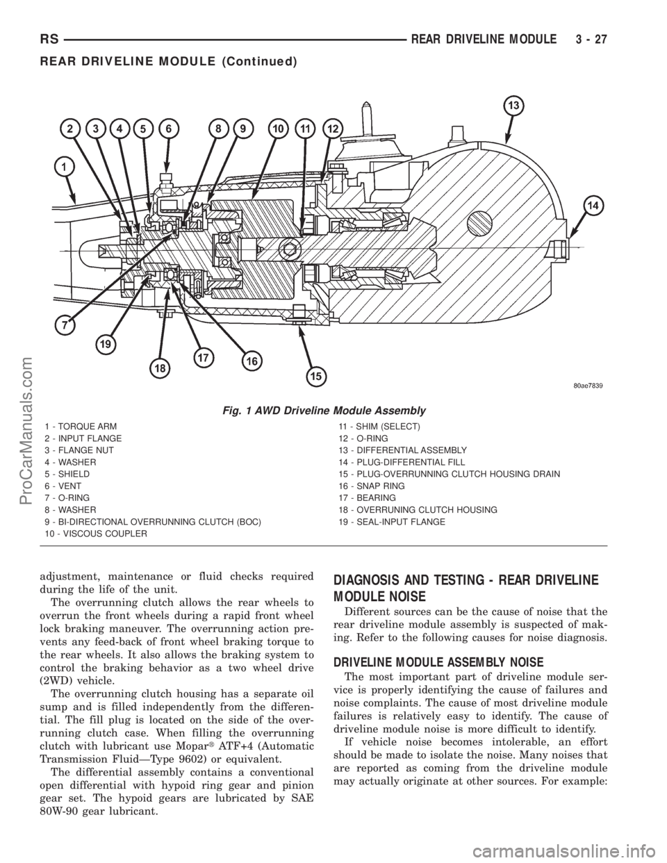
The rear driveline module assembly (Fig. 1) con-
sists of four main components:
²Bi-Directional Overrunning Clutch (BOC)
²Viscous Coupling
²Differential Assembly
²Torque Arm
The viscous coupling and bi-directional overrun-
ning clutch are contained within an overrunning
clutch housing, which fastens to the differential
assembly. The overrunning clutch housing and differ-
ential assembly have unique fluid sumps, each
requiring their own type and capacity of fluid. The
overrunning clutch housing requires MopartATF+4
(Automatic Transmission FluidÐType 9602) or equiv-
alent. The differential assembly requires
Driveline module service is limited to the following
components:
²Differential Assembly (serviced only as assem-
bly)
²Viscous Coupling
²Bi-Directional Overrunning Clutch (BOC)
²Overrunning Clutch Housing
²Seals (Input Flange, Output Flange, Overrun-
ning Clutch Housing O-rings)
²Input Flange/Shield²Torque Arm
²Vents
²FastenersOPERATION
The primary benefits of All Wheel Drive are:
²Superior straight line acceleration, and corner-
ing on all surfaces
²Better traction and handling under adverse con-
ditions, resulting in improved hill climbing ability
and safer driving.
The heart of the system is an inter-axle viscous
coupling. The vehicle retains predominantly front-
wheel drive characteristics, but the All Wheel Drive
capability takes effect when the front wheels start to
slip. Under normal level road, straight line driving,
100% of the torque is allocated to the front wheels.
The viscous coupling controls and distributes torque/
power to the rear wheels. The viscous coupling trans-
mits torque to the rear wheels in proportion of the
amount of the slippage at the front wheels. Thais
variable torque distribution is automatic with no
driver inputs required. The coupling is similar to a
multi-plate clutch. It consists of a series of closely
spaced discs, which are alternately connected to the
front and rear drive units. The unit is totally sealed
and partially filled with silicone fluid. There is no
3 - 26 REAR DRIVELINE MODULERS
ProCarManuals.com
Page 136 of 2321
adjustment, maintenance or fluid checks required
during the life of the unit.
The overrunning clutch allows the rear wheels to
overrun the front wheels during a rapid front wheel
lock braking maneuver. The overrunning action pre-
vents any feed-back of front wheel braking torque to
the rear wheels. It also allows the braking system to
control the braking behavior as a two wheel drive
(2WD) vehicle.
The overrunning clutch housing has a separate oil
sump and is filled independently from the differen-
tial. The fill plug is located on the side of the over-
running clutch case. When filling the overrunning
clutch with lubricant use MopartATF+4 (Automatic
Transmission FluidÐType 9602) or equivalent.
The differential assembly contains a conventional
open differential with hypoid ring gear and pinion
gear set. The hypoid gears are lubricated by SAE
80W-90 gear lubricant.DIAGNOSIS AND TESTING - REAR DRIVELINE
MODULE NOISE
Different sources can be the cause of noise that the
rear driveline module assembly is suspected of mak-
ing. Refer to the following causes for noise diagnosis.
DRIVELINE MODULE ASSEMBLY NOISE
The most important part of driveline module ser-
vice is properly identifying the cause of failures and
noise complaints. The cause of most driveline module
failures is relatively easy to identify. The cause of
driveline module noise is more difficult to identify.
If vehicle noise becomes intolerable, an effort
should be made to isolate the noise. Many noises that
are reported as coming from the driveline module
may actually originate at other sources. For example:
Fig. 1 AWD Driveline Module Assembly
1 - TORQUE ARM
2 - INPUT FLANGE
3 - FLANGE NUT
4 - WASHER
5 - SHIELD
6 - VENT
7 - O-RING
8 - WASHER
9 - BI-DIRECTIONAL OVERRUNNING CLUTCH (BOC)
10 - VISCOUS COUPLER11 - SHIM (SELECT)
12 - O-RING
13 - DIFFERENTIAL ASSEMBLY
14 - PLUG-DIFFERENTIAL FILL
15 - PLUG-OVERRUNNING CLUTCH HOUSING DRAIN
16 - SNAP RING
17 - BEARING
18 - OVERRUNING CLUTCH HOUSING
19 - SEAL-INPUT FLANGE
RSREAR DRIVELINE MODULE3-27
REAR DRIVELINE MODULE (Continued)
ProCarManuals.com
Page 154 of 2321

(3) Remove overrunning clutch housing drain plug
and drain fluid (Fig. 43).
(4) Install the drain plug and torque to 30 N´m (22
ft. lbs.).
(5) Re-position the drain pan under the overrun-
ning clutch housing fill plug.
(6) Remove fill plug (Fig. 44).
(7) Using a suction gun (Fig. 45), add 0.58 L (1.22
pts.) of MopartATF+4 (Automatic Transmission Flu-
idÐType 9602).
(8)
Install fill plug and torque to 30 N´m (22 ft. lbs.).
VISCOUS COUPLER
DESCRIPTION
The heart of the all-wheel drive system is the inter-
axle viscous coupling and bi-directional overrunning
clutch. Under normal driving the vehicle retains pre-
dominantly front wheel drive characteristics. The all-
wheel drive takes effect when the front wheels start to
slip. Under normal level road, straight line driving,
100% of the torque is allocated to the front wheels.
The viscous coupler allows more torque to the rear
wheels in accordance with the amount of slippage at
the front wheels. The variable torque distribution is
automatic with no driver inputs required.
OPERATION
The viscous coupler (Fig. 46) is a housing nearly
filled with a high viscosity silicone liquid and thin
metal plates alternately splined to an inner and
outer drum. The viscous coupler provides torque in
the following modes:
²Shear mode (normal operation)
²Hump mode (locked mode)
The inner plates are slotted around the radius and
the outer plates have holes in them. In the shear
mode (normal operation), the plates are evenly
spaced and the torque is created by the shearing of
the plates through the fluid and 90-100% of the
torque is applied to the rear axle. During the shear
mode, a fluid flow pattern is created from this design
(holes and slots). This fluid flow causes high pressure
on each side of each pair of plates and low pressure
between each pair of plates.
Fig. 43 Overrunning Clutch Case Drain Plug
1 - OVERRUNNING CLUTCH HOUSING DRAIN PLUG
Fig. 44 Overrunning Clutch Housing Fill Plug
1 - OVERRUNNING CLUTCH HOUSING FILL PLUG
2 - FUEL TANK
Fig. 45 Filling Overrunning Clutch Case
1 - OVERRUNNING CLUTCH HOUSING FILL HOLE
2 - SUCTION GUN
RSREAR DRIVELINE MODULE3-45
FLUID (Continued)
ProCarManuals.com
Page 304 of 2321
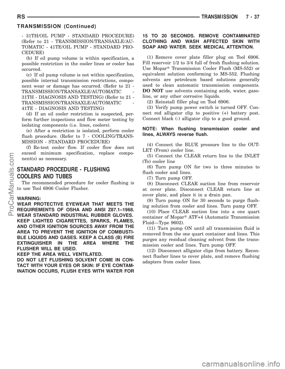
- 31TH/OIL PUMP - STANDARD PROCEDURE)
(Refer to 21 - TRANSMISSION/TRANSAXLE/AU-
TOMATIC - 41TE/OIL PUMP - STANDARD PRO-
CEDURE)
(b) If oil pump volume is within specification, a
possible restriction in the cooler lines or cooler has
occurred.
(c) If oil pump volume is not within specification,
possible internal transmission restrictions, compo-
nent wear or damage has occurred. (Refer to 21 -
TRANSMISSION/TRANSAXLE/AUTOMATIC -
31TH - DIAGNOSIS AND TESTING) (Refer to 21 -
TRANSMISSION/TRANSAXLE/AUTOMATIC -
41TE - DIAGNOSIS AND TESTING)
(d) If an oil cooler restriction is suspected, per-
form further inspections and flow meter testing by
isolating components (i.e. lines, coolers).
(e) After a restriction is isolated, perform cooler
flush procedure. (Refer to 7 - COOLING/TRANS-
MISSION - STANDARD PROCEDURE)
(f) Re-test cooler flow. If cooler flow does not
exceed minimum specification, replace compo-
nent(s) as necessary.
STANDARD PROCEDURE - FLUSHING
COOLERS AND TUBES
The recommended procedure for cooler flushing is
to use Tool 6906 Cooler Flusher.
WARNING:
WEAR PROTECTIVE EYEWEAR THAT MEETS THE
REQUIREMENTS OF OSHA AND ANSI Z87.1±1968.
WEAR STANDARD INDUSTRIAL RUBBER GLOVES.
KEEP LIGHTED CIGARETTES, SPARKS, FLAMES,
AND OTHER IGNITION SOURCES AWAY FROM THE
AREA TO PREVENT THE IGNITION OF COMBUSTI-
BLE LIQUIDS AND GASES. KEEP A CLASS (B) FIRE
EXTINGUISHER IN THE AREA WHERE THE
FLUSHER WILL BE USED.
KEEP THE AREA WELL VENTILATED.
DO NOT LET FLUSHING SOLVENT COME IN CON-
TACT WITH YOUR EYES OR SKIN: IF EYE CONTAM-
INATION OCCURS, FLUSH EYES WITH WATER FOR15 TO 20 SECONDS. REMOVE CONTAMINATED
CLOTHING AND WASH AFFECTED SKIN WITH
SOAP AND WATER. SEEK MEDICAL ATTENTION.
(1) Remove cover plate filler plug on Tool 6906.
Fill reservoir 1/2 to 3/4 full of fresh flushing solution.
Use MopartTransmission Cooler Flush (MS-552) or
equivalent solution conforming to MS-552. Flushing
solvents are petroleum based solutions generally
used to clean automatic transmission components.
DO NOTuse solvents containing acids, water, gaso-
line, or any other corrosive liquids.
(2) Reinstall filler plug on Tool 6906.
(3) Verify pump power switch is turned OFF. Con-
nect red alligator clip to positive (+) battery post.
Connect black (-) alligator clip to a good ground.
NOTE: When flushing transmission cooler and
lines, ALWAYS reverse flush.
(4) Connect the BLUE pressure line to the OUT-
LET (From) cooler line.
(5) Connect the CLEAR return line to the INLET
(To) cooler line
(6) Turn pump ON for two to three minutes to
flush cooler and lines.
(7) Turn pump OFF.
(8) Disconnect CLEAR suction line from reservoir
at cover plate. Disconnect CLEAR return line at
cover plate, and place it in a drain pan.
(9) Turn pump ON for 30 seconds to purge flush-
ing solution from cooler and lines. Turn pump OFF.
(10) Place CLEAR suction line into a one quart
container of MopartATF+4 (Automatic Transmission
FluidÐType 9602).
(11) Turn pump ON until all transmission fluid is
removed from the one quart container and lines. This
purges any residual cleaning solvent from the trans-
mission cooler and lines. Turn pump OFF.
(12) Disconnect alligator clips from battery. Recon-
nect flusher lines to cover plate, and remove flushing
adapters from cooler lines.
RSTRANSMISSION7-37
TRANSMISSION (Continued)
ProCarManuals.com
Page 582 of 2321
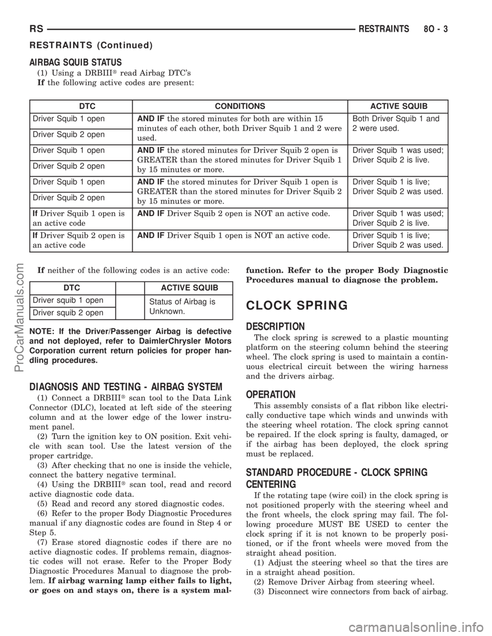
AIRBAG SQUIB STATUS
(1) Using a DRBIIItread Airbag DTC's
Ifthe following active codes are present:
DTC CONDITIONS ACTIVE SQUIB
Driver Squib 1 openAND IFthe stored minutes for both are within 15
minutes of each other, both Driver Squib 1 and 2 were
used.Both Driver Squib 1 and
2 were used.
Driver Squib 2 open
Driver Squib 1 openAND IFthe stored minutes for Driver Squib 2 open is
GREATER than the stored minutes for Driver Squib 1
by 15 minutes or more.Driver Squib 1 was used;
Driver Squib 2 is live.
Driver Squib 2 open
Driver Squib 1 openAND IFthe stored minutes for Driver Squib 1 open is
GREATER than the stored minutes for Driver Squib 2
by 15 minutes or more.Driver Squib 1 is live;
Driver Squib 2 was used.
Driver Squib 2 open
IfDriver Squib 1 open is
an active codeAND IFDriver Squib 2 open is NOT an active code.Driver Squib 1 was used;
Driver Squib 2 is live.
IfDriver Squib 2 open is
an active codeAND IFDriver Squib 1 open is NOT an active code.Driver Squib 1 is live;
Driver Squib 2 was used.
Ifneither of the following codes is an active code:
DTC ACTIVE SQUIB
Driver squib 1 open
Status of Airbag is
Unknown.
Driver squib 2 open
NOTE: If the Driver/Passenger Airbag is defective
and not deployed, refer to DaimlerChrysler Motors
Corporation current return policies for proper han-
dling procedures.
DIAGNOSIS AND TESTING - AIRBAG SYSTEM
(1) Connect a DRBIIItscan tool to the Data Link
Connector (DLC), located at left side of the steering
column and at the lower edge of the lower instru-
ment panel.
(2) Turn the ignition key to ON position. Exit vehi-
cle with scan tool. Use the latest version of the
proper cartridge.
(3) After checking that no one is inside the vehicle,
connect the battery negative terminal.
(4) Using the DRBIIItscan tool, read and record
active diagnostic code data.
(5) Read and record any stored diagnostic codes.
(6) Refer to the proper Body Diagnostic Procedures
manual if any diagnostic codes are found in Step 4 or
Step 5.
(7) Erase stored diagnostic codes if there are no
active diagnostic codes. If problems remain, diagnos-
tic codes will not erase. Refer to the Proper Body
Diagnostic Procedures Manual to diagnose the prob-
lem.If airbag warning lamp either fails to light,
or goes on and stays on, there is a system mal-function. Refer to the proper Body Diagnostic
Procedures manual to diagnose the problem.
CLOCK SPRING
DESCRIPTION
The clock spring is screwed to a plastic mounting
platform on the steering column behind the steering
wheel. The clock spring is used to maintain a contin-
uous electrical circuit between the wiring harness
and the drivers airbag.
OPERATION
This assembly consists of a flat ribbon like electri-
cally conductive tape which winds and unwinds with
the steering wheel rotation. The clock spring cannot
be repaired. If the clock spring is faulty, damaged, or
if the airbag has been deployed, the clock spring
must be replaced.
STANDARD PROCEDURE - CLOCK SPRING
CENTERING
If the rotating tape (wire coil) in the clock spring is
not positioned properly with the steering wheel and
the front wheels, the clock spring may fail. The fol-
lowing procedure MUST BE USED to center the
clock spring if it is not known to be properly posi-
tioned, or if the front wheels were moved from the
straight ahead position.
(1) Adjust the steering wheel so that the tires are
in a straight ahead position.
(2) Remove Driver Airbag from steering wheel.
(3) Disconnect wire connectors from back of airbag.
RSRESTRAINTS8O-3
RESTRAINTS (Continued)
ProCarManuals.com