2001 DODGE TOWN AND COUNTRY door lock
[x] Cancel search: door lockPage 514 of 2321
POWER SYSTEMS
TABLE OF CONTENTS
page page
POWER LIFTGATE SYSTEM.................. 1
POWER SLIDING DOOR SYSTEM............ 19
POWER LOCKS........................... 39POWER MIRRORS........................ 45
POWER SEATS........................... 49
POWER WINDOWS........................ 60
POWER LIFTGATE SYSTEM
TABLE OF CONTENTS
page page
POWER LIFTGATE SYSTEM
DESCRIPTION............................2
OPERATION.............................3
DIAGNOSIS AND TESTING..................4
DIAGNOSIS AND TESTING - POWER
LIFTGATE SYSTEM......................4
STANDARD PROCEDURE...................9
LIFTGATE ADJUSTMENT..................9
POWER LIFTGATE LEARN CYCLE..........9
PINCH SENSOR
DESCRIPTION............................9
OPERATION.............................9
REMOVAL...............................9
INSTALLATION...........................10
FULL OPEN SWITCH
DESCRIPTION...........................10
OPERATION.............................10
REMOVAL..............................10
INSTALLATION...........................10
LIFTGATE MOTOR
DESCRIPTION...........................11
OPERATION.............................11
REMOVAL..............................11
INSTALLATION...........................11
ENGAGE ACTUATOR
DESCRIPTION...........................12
OPERATION.............................12
REMOVAL..............................12
INSTALLATION...........................12TRANSVERSE BRACKET
DESCRIPTION...........................13
OPERATION.............................13
REMOVAL..............................13
INSTALLATION...........................13
LIFT GEAR & LINK ROD
DESCRIPTION...........................14
OPERATION.............................14
REMOVAL..............................14
INSTALLATION...........................14
LATCH
DESCRIPTION...........................15
OPERATION.............................15
REMOVAL..............................15
INSTALLATION...........................15
LATCH ACTUATOR
DESCRIPTION...........................16
OPERATION.............................16
REMOVAL..............................16
INSTALLATION...........................16
EXTERIOR HANDLE SWITCH
DESCRIPTION...........................17
OPERATION.............................17
REMOVAL..............................17
INSTALLATION...........................17
CHIME/THERMISTOR
DESCRIPTION...........................18
OPERATION.............................18
REMOVAL..............................18
INSTALLATION...........................18
RSPOWER SYSTEMS8N-1
ProCarManuals.com
Page 528 of 2321
LATCH
DESCRIPTION
Vehicles equipped with a power liftgate, utilize a
power cinch/release latch. This latch performs the
same features as a manual liftgate latch as well as
the power cinch and / or release capability. A second
type of power latch can also be found on some RS
models, this latch is designed to perform a power
release only. The power cinch and release capability
is accomplished by an actuator mounted to the lead-
ing edge of the latch assembly. The latch is located in
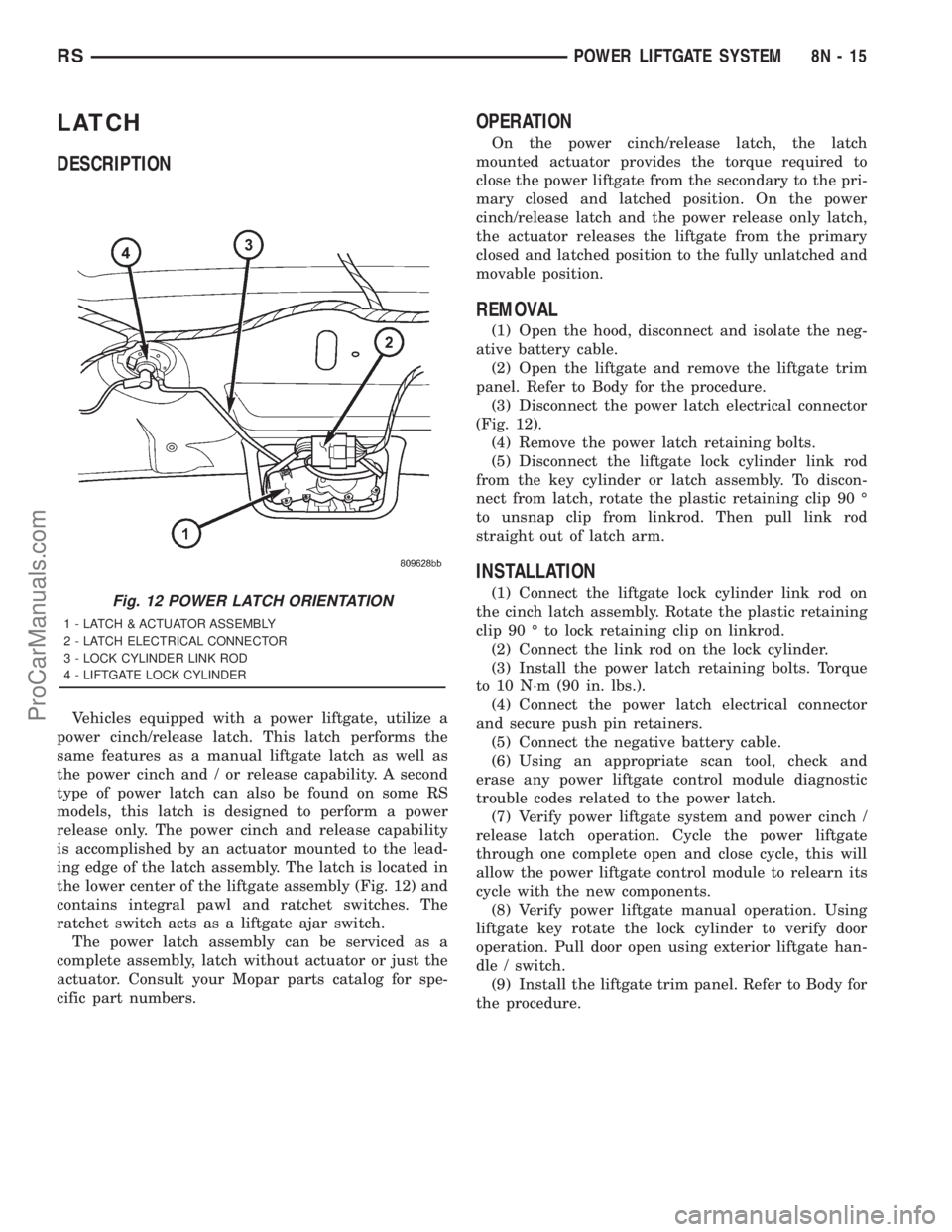
the lower center of the liftgate assembly (Fig. 12) and
contains integral pawl and ratchet switches. The
ratchet switch acts as a liftgate ajar switch.
The power latch assembly can be serviced as a
complete assembly, latch without actuator or just the
actuator. Consult your Mopar parts catalog for spe-
cific part numbers.
OPERATION
On the power cinch/release latch, the latch
mounted actuator provides the torque required to
close the power liftgate from the secondary to the pri-
mary closed and latched position. On the power
cinch/release latch and the power release only latch,
the actuator releases the liftgate from the primary
closed and latched position to the fully unlatched and
movable position.
REMOVAL
(1) Open the hood, disconnect and isolate the neg-
ative battery cable.
(2) Open the liftgate and remove the liftgate trim
panel. Refer to Body for the procedure.
(3) Disconnect the power latch electrical connector
(Fig. 12).
(4) Remove the power latch retaining bolts.
(5) Disconnect the liftgate lock cylinder link rod
from the key cylinder or latch assembly. To discon-
nect from latch, rotate the plastic retaining clip 90 É
to unsnap clip from linkrod. Then pull link rod
straight out of latch arm.
INSTALLATION
(1) Connect the liftgate lock cylinder link rod on
the cinch latch assembly. Rotate the plastic retaining
clip 90 É to lock retaining clip on linkrod.
(2) Connect the link rod on the lock cylinder.
(3) Install the power latch retaining bolts. Torque
to 10 N´m (90 in. lbs.).
(4) Connect the power latch electrical connector
and secure push pin retainers.
(5) Connect the negative battery cable.
(6) Using an appropriate scan tool, check and
erase any power liftgate control module diagnostic
trouble codes related to the power latch.
(7) Verify power liftgate system and power cinch /
release latch operation. Cycle the power liftgate
through one complete open and close cycle, this will
allow the power liftgate control module to relearn its
cycle with the new components.
(8) Verify power liftgate manual operation. Using
liftgate key rotate the lock cylinder to verify door
operation. Pull door open using exterior liftgate han-
dle / switch.
(9) Install the liftgate trim panel. Refer to Body for
the procedure.Fig. 12 POWER LATCH ORIENTATION
1 - LATCH & ACTUATOR ASSEMBLY
2 - LATCH ELECTRICAL CONNECTOR
3 - LOCK CYLINDER LINK ROD
4 - LIFTGATE LOCK CYLINDER
RSPOWER LIFTGATE SYSTEM8N-15
ProCarManuals.com
Page 532 of 2321
POWER SLIDING DOOR SYSTEM
TABLE OF CONTENTS
page page
POWER SLIDING DOOR SYSTEM
DESCRIPTION...........................19
OPERATION.............................21
DIAGNOSIS AND TESTING.................22
DIAGNOSIS AND TESTING - POWER
SLIDING DOOR SYSTEM.................22
STANDARD PROCEDURE..................28
WELLNUT REPLACEMENT...............28
POWER DOOR LEARN CYCLE............28
SLIDING DOOR ADJUSTMENT............28
LATCH
DESCRIPTION...........................29
OPERATION.............................29
REMOVAL..............................29
INSTALLATION...........................30
SLIDING DOOR MOTOR
DESCRIPTION...........................30
OPERATION.............................30
REMOVAL..............................31
INSTALLATION...........................31
FULL OPEN SWITCH
DESCRIPTION...........................31
OPERATION.............................31
LEFT B-PILLAR SWITCH
DESCRIPTION...........................32
OPERATION.............................32
REMOVAL..............................32INSTALLATION...........................32
RIGHT B-PILLAR SWITCH
DESCRIPTION...........................32
OPERATION.............................32
REMOVAL..............................32
INSTALLATION...........................32
LOWER DRIVE UNIT
DESCRIPTION...........................33
OPERATION.............................33
REMOVAL..............................33
INSTALLATION...........................34
LOWER DRIVE UNIT TRACK & RACK
DESCRIPTION...........................34
OPERATION.............................34
REMOVAL..............................34
INSTALLATION...........................35
WIRING HARNESS
DESCRIPTION...........................35
OPERATION.............................35
REMOVAL..............................35
INSTALLATION...........................36
FLEX DRIVE
DESCRIPTION...........................36
OPERATION.............................36
REMOVAL..............................37
INSTALLATION...........................38
POWER SLIDING DOOR
SYSTEM
DESCRIPTION
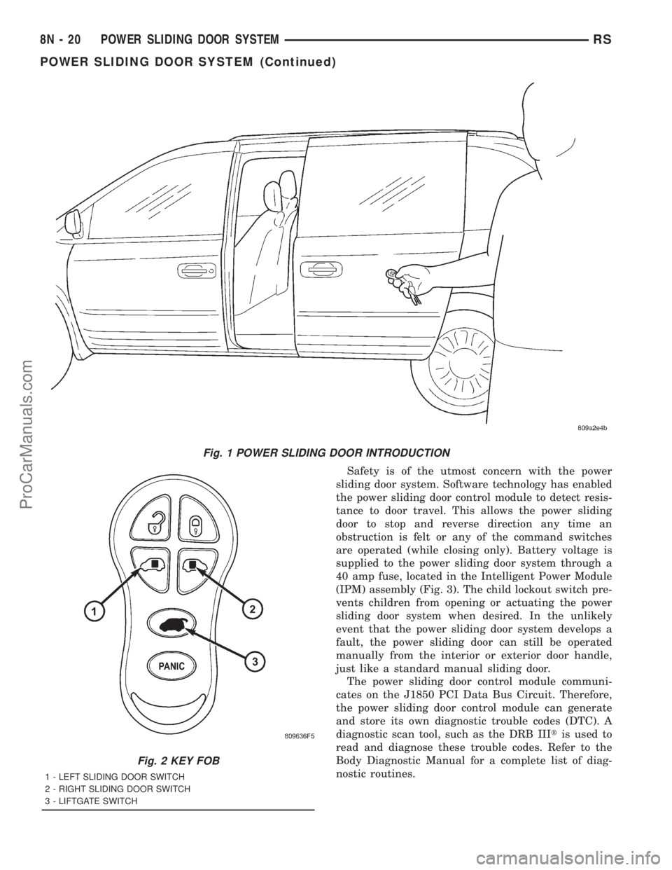
Some vehicles are equipped with a power opening
and closing sliding door system (Fig. 1). Depending
on how the vehicle is ordered it may be equipped
with only a right side power door or right and left
side power doors. This power sliding door system is a
complex system consisting of many components.
Some of these components are the door motor, latch
assembly, sliding door control module, lower drive
unit, flex drive assembly, wire harness and track,
lower drive unit track and rack assembly, full open
switch, B-pillar switch, overhead console switch, key
fob switches (Fig. 2), pawl switch, ratchet switch and
child lockout and handle switches.
Each power side door has its own door control mod-
ule, located in the center of the door behind the door
trim panel. (Refer to 8 - ELECTRICAL/ELEC-TRONIC CONTROL MODULES/DOOR CONTROL
MODULE - DESCRIPTION) The power side door
motor is located in the front portion of the door, on
the inner door panel sheet metal. The latch assembly
is located in the rear of the power side door, near the
body line. The lower drive unit is attached to the
lower door hinge. The flex drive assembly connects
the door motor to the lower drive unit. The wire har-
ness and track and the lower drive unit track are vis-
ible with the door open in the lower door sill area.
The power side door full open switch is located under
the lower drive unit and is part of the hold open
latch assembly. The pawl, ratchet, handle and child
lockout switches are all located on the power side
door latch assembly. The B-pillar switch, as it will be
referred to, is an open and close command switch
located on the vehicles interior body side B-pillar
trim. The overhead console switch, is an open and
close command switch located in the vehicle's over-
head console. More detailed information can be found
on these components later in this section.
RSPOWER SLIDING DOOR SYSTEM8N-19
ProCarManuals.com
Page 533 of 2321
Safety is of the utmost concern with the power
sliding door system. Software technology has enabled
the power sliding door control module to detect resis-
tance to door travel. This allows the power sliding
door to stop and reverse direction any time an
obstruction is felt or any of the command switches
are operated (while closing only). Battery voltage is
supplied to the power sliding door system through a
40 amp fuse, located in the Intelligent Power Module
(IPM) assembly (Fig. 3). The child lockout switch pre-
vents children from opening or actuating the power
sliding door system when desired. In the unlikely
event that the power sliding door system develops a
fault, the power sliding door can still be operated
manually from the interior or exterior door handle,
just like a standard manual sliding door.
The power sliding door control module communi-
cates on the J1850 PCI Data Bus Circuit. Therefore,
the power sliding door control module can generate
and store its own diagnostic trouble codes (DTC). A
diagnostic scan tool, such as the DRB IIItis used to
read and diagnose these trouble codes. Refer to the
Body Diagnostic Manual for a complete list of diag-
nostic routines.
Fig. 1 POWER SLIDING DOOR INTRODUCTION
Fig. 2 KEY FOB
1 - LEFT SLIDING DOOR SWITCH
2 - RIGHT SLIDING DOOR SWITCH
3 - LIFTGATE SWITCH
8N - 20 POWER SLIDING DOOR SYSTEMRS
POWER SLIDING DOOR SYSTEM (Continued)
ProCarManuals.com
Page 534 of 2321

NOTE: It may be possible to generate Sliding Door
Diagnostic Trouble Codes during normal power
sliding door operation. Refer to the Body Diagnos-
tic Manual for a complete list of diagnostic routines.
For additional information, (Refer to 8 - ELECTRI-
CAL/POWER DOORS - OPERATION) . For a com-
plete power sliding door system wiring schematic,
refer to Wiring Diagrams. For power sliding door sys-
tem operation instructions, refer to the vehicle owner
manual.
WARNING: BE CERTAIN TO READ ALL WARNINGS
AND CAUTIONS IN POWER SLIDING DOOR OPER-
ATION BEFORE ATTEMPTING ANY SERVICE OF
POWER SLIDING DOOR SYSTEM OR COMPO-
NENTS.
OPERATION
With the push of a power sliding door open/close
command switch (key fob, overhead console or B-pil-
lar mounted) a signal is sent out to the Body Control
Module (BCM). The BCM then sends a signal out on
the PCI Data Bus circuit (J1850) to the power sliding
door module. The power sliding door module then
signals the power sliding door latch to release the
door to the unlatched and movable position. The
motor then starts an open cycle.
During the door open cycle, if the power sliding
door module detects sufficient resistance to door
travel, such as an obstruction in the door's path, the
power sliding door module will immediately stop door
movement and reverse door travel to the full open orclosed position. The ability for the power sliding door
module to detect resistance to door travel is accom-
plished by hall effect sensors and the door motor
speed.
The power sliding door control module has the abil-
ity to learn. Anytime a door is opened or closed using
the power sliding door system the module learns
from its cycle. If a replacement power sliding door
component is installed or a door adjustment is made,
the module must re-learn the effort required to open
or close the door. A learn cycle can be performed with
a Diagnostic Scan Tool, such as the DRB IIIt, or with
a complete cycle of the door, using any one of the
command switches. Refer to Standard Procedures in
this section for detailed instructions.
The power sliding door system is designed with a
number of system inhibitors. These inhibitors are
necessary for safety and/or feasibility of the power
sliding door system. See the power sliding door sys-
tem inhibitors noted below:
POWER SLIDING DOOR SYSTEM INHIBITORS
²The power sliding door must be in thefullopen
or closed position in order for the power sliding door
system to start a cycle. If the door is not in this posi-
tion (based on the input from the full open, pawl or
ratchet switches) the door control module will not
respond to command switch inputs.
²The vehicles transmission must be inpark or
neutralin order for the power sliding door system to
start a cycle.
²The vehicles child lockout switch must be in the
ªUNLOCKEDº position in order for the power sliding
door systems B-pillar switches to function.
²If multiple obstacles are detected during the
same power open or close cycle the power sliding
door may go into full manual mode.
²If severe Diagnostic Trouble Codes (DTC) are
stored in the power sliding door control module the
power sliding door may go into full manual mode.
²Due to the high pressure created in the passen-
ger compartment with the blower motor on high, the
power sliding door may not complete a power close
cycle unless a window is cracked, allowing the pres-
sure to escape. This situation will only be experi-
enced on some vehicles, or vehicles with brand new
side door weather seals installed. Refer to the Side
Door Adjustment procedure in the Standard Proce-
dures section of this group.
²The vehicles fuel tank filler door must be in the
closed position. Due to the sliding door interference
with the open fuel tank filler door, mechanical link-
age prevents the side door from opening and striking
the fuel door. Refer to the Body section of this man-
ual for detailed information on the fuel door lockout
feature.Fig. 3 POWER SIDE DOOR FUSE LOCATION
RSPOWER SLIDING DOOR SYSTEM8N-21
POWER SLIDING DOOR SYSTEM (Continued)
ProCarManuals.com
Page 538 of 2321
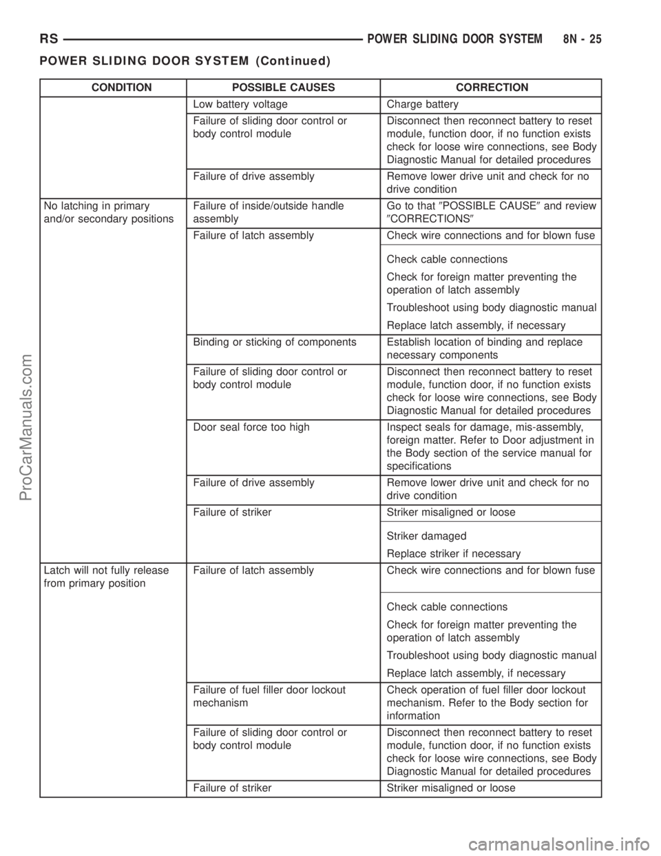
CONDITION POSSIBLE CAUSES CORRECTION
Low battery voltage Charge battery
Failure of sliding door control or
body control moduleDisconnect then reconnect battery to reset
module, function door, if no function exists
check for loose wire connections, see Body
Diagnostic Manual for detailed procedures
Failure of drive assembly Remove lower drive unit and check for no
drive condition
No latching in primary
and/or secondary positionsFailure of inside/outside handle
assemblyGo to that9POSSIBLE CAUSE9and review
9CORRECTIONS9
Failure of latch assembly Check wire connections and for blown fuse
Check cable connections
Check for foreign matter preventing the
operation of latch assembly
Troubleshoot using body diagnostic manual
Replace latch assembly, if necessary
Binding or sticking of components Establish location of binding and replace
necessary components
Failure of sliding door control or
body control moduleDisconnect then reconnect battery to reset
module, function door, if no function exists
check for loose wire connections, see Body
Diagnostic Manual for detailed procedures
Door seal force too high Inspect seals for damage, mis-assembly,
foreign matter. Refer to Door adjustment in
the Body section of the service manual for
specifications
Failure of drive assembly Remove lower drive unit and check for no
drive condition
Failure of striker Striker misaligned or loose
Striker damaged
Replace striker if necessary
Latch will not fully release
from primary positionFailure of latch assembly Check wire connections and for blown fuse
Check cable connections
Check for foreign matter preventing the
operation of latch assembly
Troubleshoot using body diagnostic manual
Replace latch assembly, if necessary
Failure of fuel filler door lockout
mechanismCheck operation of fuel filler door lockout
mechanism. Refer to the Body section for
information
Failure of sliding door control or
body control moduleDisconnect then reconnect battery to reset
module, function door, if no function exists
check for loose wire connections, see Body
Diagnostic Manual for detailed procedures
Failure of striker Striker misaligned or loose
RSPOWER SLIDING DOOR SYSTEM8N-25
POWER SLIDING DOOR SYSTEM (Continued)
ProCarManuals.com
Page 542 of 2321
LATCH
DESCRIPTION
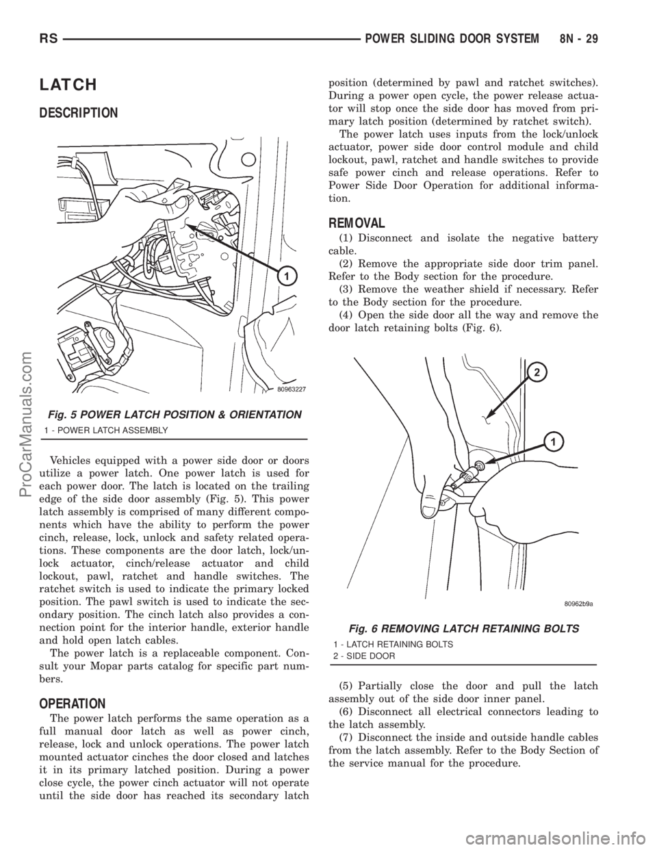
Vehicles equipped with a power side door or doors
utilize a power latch. One power latch is used for
each power door. The latch is located on the trailing
edge of the side door assembly (Fig. 5). This power
latch assembly is comprised of many different compo-
nents which have the ability to perform the power
cinch, release, lock, unlock and safety related opera-
tions. These components are the door latch, lock/un-
lock actuator, cinch/release actuator and child
lockout, pawl, ratchet and handle switches. The
ratchet switch is used to indicate the primary locked
position. The pawl switch is used to indicate the sec-
ondary position. The cinch latch also provides a con-
nection point for the interior handle, exterior handle
and hold open latch cables.
The power latch is a replaceable component. Con-
sult your Mopar parts catalog for specific part num-
bers.
OPERATION
The power latch performs the same operation as a
full manual door latch as well as power cinch,
release, lock and unlock operations. The power latch
mounted actuator cinches the door closed and latches
it in its primary latched position. During a power
close cycle, the power cinch actuator will not operate
until the side door has reached its secondary latchposition (determined by pawl and ratchet switches).
During a power open cycle, the power release actua-
tor will stop once the side door has moved from pri-
mary latch position (determined by ratchet switch).
The power latch uses inputs from the lock/unlock
actuator, power side door control module and child
lockout, pawl, ratchet and handle switches to provide
safe power cinch and release operations. Refer to
Power Side Door Operation for additional informa-
tion.
REMOVAL
(1) Disconnect and isolate the negative battery
cable.
(2) Remove the appropriate side door trim panel.
Refer to the Body section for the procedure.
(3) Remove the weather shield if necessary. Refer
to the Body section for the procedure.
(4) Open the side door all the way and remove the
door latch retaining bolts (Fig. 6).
(5) Partially close the door and pull the latch
assembly out of the side door inner panel.
(6) Disconnect all electrical connectors leading to
the latch assembly.
(7) Disconnect the inside and outside handle cables
from the latch assembly. Refer to the Body Section of
the service manual for the procedure.
Fig. 5 POWER LATCH POSITION & ORIENTATION
1 - POWER LATCH ASSEMBLY
Fig. 6 REMOVING LATCH RETAINING BOLTS
1 - LATCH RETAINING BOLTS
2 - SIDE DOOR
RSPOWER SLIDING DOOR SYSTEM8N-29
ProCarManuals.com
Page 543 of 2321
(8) Disconnect the hold open latch cable from the
latch assembly. Refer to the Body Section of the ser-
vice manual for the procedure.
(9) Disconnect lock actuator link rod from the
latch assembly.
(10) Remove the latch assembly from the vehicle.
INSTALLATION
(1) Position the latch assembly in the vehicle. Be
certain all latch mounted components are installed
on the replacement latch assembly. If not, transfer
components from the old latch to the new latch
assembly.
(2) Connect the lock actuator link rod on the latch
assembly.
(3) Connect the hold open latch cable on the latch
assembly. Refer to the procedure in this section for
detailed instructions.
(4) Connect the inside and outside handle cables
on the latch assembly. Refer to the procedure in the
Body section for detailed instructions.
(5) Connect all electrical connectors leading to the
latch assembly.
(6) With assistance from another person, position
the side door and install the door latch retaining
bolts. Torque to 10 - 12 N´m (100 in. lbs.).
(7) Install the weathershield if necessary. Refer to
the procedure in the Body section for detailed
instructions.
(8) Install the appropriate side door trim panel.
Refer to the procedure in the Body section for
detailed instructions.
(9) Connect the negative battery cable.
SLIDING DOOR MOTOR
DESCRIPTION
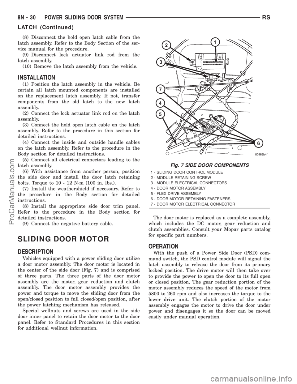
Vehicles equipped with a power sliding door utilize
a door motor assembly. The door motor is located in
the center of the side door (Fig. 7) and is comprised
of three parts. The three parts of the door motor
assembly are the motor, gear reduction and clutch
assembly. The door motor assembly provides the
power and torque to move the sliding door from the
open/closed position to full closed/open position, after
the power latching mechanism has released.
Special wellnuts and screws are used in the side
door inner panel to retain the door motor to the door
panel. Refer to Standard Procedures in this section
for additional wellnut information.The door motor is replaced as a complete assembly,
which includes the DC motor, gear reduction and
clutch assemblies. Consult your Mopar parts catalog
for specific part numbers.
OPERATION
With the push of a Power Side Door (PSD) com-
mand switch, the PSD control module will signal the
latch assembly to release the door from its primary
locked position. The drive motor will then take over
to provide the power to open the door to its full open
or closed position. The gear reduction portion of the
motor assembly reduces the speed of the motor from
5800 to 260 rpm and also increases the torque to the
lower drive unit. The clutch portion of the motor
assembly engages the motor to drive the door under
power and disengages it so the door can be moved
easily under manual operation.
Fig. 7 SIDE DOOR COMPONENTS
1 - SLIDING DOOR CONTROL MODULE
2 - MODULE RETAINING SCREW
3 - MODULE ELECTRICAL CONNECTORS
4 - DOOR MOTOR ASSEMBLY
5 - FLEX DRIVE ASSEMBLY
6 - DOOR MOTOR RETAINING FASTENERS
7 - DOOR MOTOR ELECTRICAL CONNECTOR
8N - 30 POWER SLIDING DOOR SYSTEMRS
LATCH (Continued)
ProCarManuals.com