2001 DODGE TOWN AND COUNTRY ignition
[x] Cancel search: ignitionPage 2209 of 2321
(1) Check the fuse (Fuse 10 - 40 ampere) in the
Intelligent Power Module (IPM). If OK, go to Step 2.
If not OK, repair the shorted circuit or component as
required and replace the faulty fuse.
(2) Turn the ignition switch to the On position. Be
certain that the heater-A/C control power is turned
on. Check for battery voltage at the fuse (Fuse 10 -
40 ampere) in the IPM. If OK, go to Step 3. If not
OK, proceed to diagnosis of the front blower motor
relay. (Refer to 24 - HEATING & AIR CONDITION-
ING/CONTROLS - FRONT/BLOWER MOTOR
RELAY - DIAGNOSIS AND TESTING).
(3) Turn the ignition switch to the Off position.
Disconnect and isolate the battery negative cable.
Disconnect the front HVAC wire harness connector
for the front blower motor resistor (Manual Temper-
ature Control) or the front blower power module
(Automatic Temperature Control) from the resistor or
module connector receptacle. Reconnect the battery
negative cable. Turn the ignition switch to the On
position. Be certain that the heater-A/C control
power is turned on. Check for battery voltage at the
fused front blower motor relay output circuit cavity
of the front HVAC wire harness connector for thefront blower motor resistor (MTC) or the front blower
power module (ATC). If OK, go to Step 4. If not OK,
repair the open fused front blower motor relay output
circuit to the IPM as required.
(4) Turn the ignition switch to the Off position.
Disconnect and isolate the battery negative cable.
Disconnect the front blower motor pigtail wire con-
nector from the connector receptacle of the front
blower motor resistor (MTC) or the front blower
power module (ATC). Use jumper wires to connect a
battery and ground feeds to the blower motor pigtail
wire connector. The blower motor should operate. If
OK with MTC, proceed to diagnosis of the front
blower motor resistor. (Refer to 24 - HEATING & AIR
CONDITIONING/CONTROLS - FRONT/BLOWER
MOTOR RESISTOR - DIAGNOSIS AND TESTING).
If OK with ATC, use a DRBIII scan tool to diagnose
the front blower power module. Refer to the appropri-
ate diagnostic information. If not OK with MTC or
ATC, replace the faulty front blower motor.
BLOWER MOTOR NOISE OR VIBRATION
Refer to the Blower Motor Noise/Vibration Diagno-
sis chart (Fig. 8).
24 - 46 DISTRIBUTION - FRONTRS
BLOWER MOTOR (Continued)
ProCarManuals.com
Page 2218 of 2321
A/C DISTRIBUTION DUCT
REMOVAL
(1) Remove the trim from the right quarter inner
panel and the right D pillar. (Refer to 23 - BODY/IN-
TERIOR/RIGHT QUARTER TRIM PANEL -
REMOVAL).
(2) Slide the rear air conditioning distribution duct
upwards far enough to disengage it from the outlet at
the top of the rear heater-A/C unit housing (Fig. 2).
(3) While pulling the lower end of the auxiliary air
conditioning distribution duct away from the rear
heater-A/C unit outlet, disengage the upper end of
the distribution duct from the headliner duct.
(4) Remove the auxiliary air conditioning distribu-
tion duct from the vehicle.
INSTALLATION
(1) Align the upper end of the rear air conditioning
distribution duct to the headliner duct (Fig. 2).
(2) Slide the upper end of the rear air conditioning
distribution duct onto the headliner duct far enough
to align the lower end of the duct with the outlet at
the top of the rear heater-A/C unit housing.
(3) Slide the rear air conditioning distribution duct
downwards far enough to engage it onto the outlet at
the top of the rear heater-A/C unit housing.
(4) Reinstall the trim onto the right quarter inner
panel and the right D pillar. (Refer to 23 - BODY/IN-
TERIOR/RIGHT QUARTER TRIM PANEL -
INSTALLATION).
BLOWER MOTOR
DESCRIPTION
The blower motor is a 12-volt, Direct Current (DC)
motor with a squirrel cage-type blower wheel that is
secured to the blower motor shaft (Fig. 3). The
blower motor and wheel are located in a housing
near the top of the rear heater-A/C unit in the pas-
senger compartment behind the right rear wheel
house. The rear heater-A/C unit housing must be
removed from the vehicle to access the blower motor
and blower wheel for service. The blower motor and
blower motor wheel are a factory balanced unit and
cannot be adjusted or repaired. If faulty or damaged,
the blower motor and blower wheel must be replaced
as a unit.
OPERATION
The rear blower motor will operate whenever the
ignition switch is in the On position, the heater-A/C
control power is turned on, and the rear heater-A/C
Fig. 2 Rear A/C Distribution Duct
1 - HEADLINER DUCT
2 - REAR A/C DISTRIBUTION DUCT
3 - REAR HEATER-A/C UNIT OUTLET
Fig. 3 Blower Motor
1 - REAR HEATER-A/C UNIT HOUSING
2 - BLOWER MOTOR
3 - SCREW (3)
4 - BLOWER PIGTAIL WIRE
RSDISTRIBUTION - REAR24-55
ProCarManuals.com
Page 2219 of 2321
system control switch on the front heater-A/C control
is not in the Off position. The blower motor can only
be turned off by turning off the rear system at the
front heater-A/C control. The blower motor receives
battery current whenever the rear blower motor
relay is energized. The rear blower motor relay out-
put circuit is protected by a fuse in the Intelligent
Power Module (IPM) located in the engine compart-
ment near the battery. In the MTC system, the
blower motor speed is controlled by regulating the
path to ground through the blower control switch and
the blower motor resistor. In the ATC system, the
blower motor speed is controlled by an electronic
blower power module, which uses a pulse width mod-
ulated input from the ATC module and feedback from
the blower motor to regulate the blower motor
ground path it provides. The blower motor and wheel
are used to control the velocity of air moving through
the rear heater-A/C unit housing. The blower motor
controls the velocity of the air flowing through the
rear heater-A/C housing by spinning the blower
wheel within the housing at the selected speed or, in
the ATC system, at the selected or programmed
speed.
DIAGNOSIS AND TESTING - REAR BLOWER
MOTOR
BLOWER MOTOR INOPERATIVE
(1) Check the fuse (Fuse 12 - 25 ampere) in the
Intelligent Power Module (IPM). If OK, go to Step 2.
If not OK, repair the shorted circuit or component as
required and replace the faulty fuse.
(2) Turn the ignition switch to the On position. Be
certain that the rear heater-A/C control power is
turned on. Check for battery voltage at the fuse
(Fuse 12 - 25 ampere) in the IPM. If OK, go to Step
3. If not OK, proceed to diagnosis of the rear blower
motor relay. (Refer to 24 - HEATING & AIR CONDI-TIONING/CONTROLS - REAR/BLOWER MOTOR
RELAY - DIAGNOSIS AND TESTING).
(3) Turn the ignition switch to the Off position.
Disconnect and isolate the battery negative cable.
Disconnect the rear HVAC wire harness connector for
the rear blower motor resistor (Manual Temperature
Control) or the rear blower power module (Automatic
Temperature Control) from the resistor or module
connector receptacle. Reconnect the battery negative
cable. Turn the ignition switch to the On position. Be
certain that the rear heater-A/C control power is
turned on. Check for battery voltage at the fused
rear blower motor relay output circuit cavity of the
rear HVAC wire harness connector for the rear
blower motor resistor (MTC) or the rear blower
power module (ATC). If OK, go to Step 4. If not OK,
repair the open fused front blower motor relay output
circuit to the IPM as required.
(4) Turn the ignition switch to the Off position.
Disconnect and isolate the battery negative cable.
Disconnect the rear blower motor pigtail wire connec-
tor from the take out and connector of the rear
HVAC wire harness (MTC) or the connector recepta-
cle of the rear blower power module (ATC). Use
jumper wires to connect a battery and ground feeds
to the blower motor pigtail wire connector. The
blower motor should operate. If OK with MTC, pro-
ceed to diagnosis of the rear blower motor resistor.
(Refer to 24 - HEATING & AIR CONDITIONING/
CONTROLS - REAR/BLOWER MOTOR RESISTOR -
DIAGNOSIS AND TESTING). If OK with ATC, use a
DRBIII scan tool to diagnose the rear blower power
module. Refer to the appropriate diagnostic informa-
tion. If not OK with MTC or ATC, replace the faulty
rear blower motor.
BLOWER MOTOR NOISE OR VIBRATION
Refer to the Blower Motor Noise/Vibration Diagno-
sis chart (Fig. 4).
24 - 56 DISTRIBUTION - REARRS
BLOWER MOTOR (Continued)
ProCarManuals.com
Page 2277 of 2321
OPERATION
The supplemental heater unit is activated via the
temperature slide control or knob on the vehicle HVAC
control unit. If the control slide or knob is moved to or
above the upper set point the heater is activated. The
unit can operate in a full or partial load range as well
as an idle mode all dependent on the engine coolanttemperature. The heater unit will also turn off if the
HVAC temperature control is lowered to less than the
lower set point. The heater unit can take up to three
minutes to completely shut down when either the
heater temperature is set below the lower set point or
the vehicle ignition is shut down.
DIAGNOSIS AND TESTING - DIESEL SUPPLEMENTAL HEATER - DCHA
The following table lists possible fault symptoms of
diesel fueled heaters.
SYMPTOM POSSIBLE CAUSES
Smell of diesel fuel Check heater system integration in vehicle's fuel system. Check fuel
lines for leakage, kinks or obstructions. If OK, Inspect the inlet muffler,
drain as necessary. Re-test the unit and re-inspect. Inspect the
exhaust tube and heater unit for the presence of external fuel. If a
volume is observed on the unit or in the exhaust tube or after draining
and testing. Remove heater unit from vehicle and repair or replace
components as required.
Heater does not achieve full load
operation.Check heater operation with DRB-III and replace components as
required.
Continuous white smoke from heater
exhaust during combustion operation.Check heater operation with DRB-III and replace components as
required. White smoke is typical in extreme weather conditions.
Heater can not be switched off. Check heater operation with DRB-III and replace components as
required.
Heater does not operate. Diagnosis cabin heater ECU using the DRB-III and the procedures
listed in Vehicle Performance under Cabin Heater Diagnosis in Group
18.
Loss of coolant (Leakage) or heater
develops smoke during combustion
operation and exhaust has an
extremely sweet smell.Inspect coolant hoses for leakage, kinks or loose hose connection.
Inspect the exhaust tube assembly for continuous flow, if OK there is
an internal heater leak and unit should be inspected and components
should be replaced as required.
Loss of fuel (dripping). Check heater system integration in vehicles fuel system. Check fuel
line connection for leakage. If OK there is an internal leak and unit
should be inspected and replaced as required.
EXHAUST TUBE
REMOVAL
WARNING: THERE IS A POTENTIAL DANGER OF
SKIN BURNS AS THE HEATER AND ITS COMPO-
NENTS MAY BE VERY HOT. MAKE SURE THE
HEATER IS ALLOWED TO COOL DOWN BEFORE
ANY SERVICE WORK IS ATTEMPTED.
WARNING: THERE IS A POTENTIAL DANGER OF
SKIN BURNS AS THE EXHAUST SYSTEM MAY BE
VERY HOT. MAKE SURE THE EXHAUST SYSTEM ISALLOWED TO COOL DOWN BEFORE ANY SERVICE
WORK IS ATTEMPTED ON THE CABIN HEATER.
(1) Elevate vehicle on a lift taking note of the
exhaust tube flexible section.
(2) Remove the exhaust clamp at the flexible pipe
and steel pipe connection (Fig. 4).
(3) Remove the clamp at the flexible pipe connec-
tion and the heater unit housing (if required).
(4) Remove the three screws holding the exhaust
pipe to the body.
(5) Remove the steel exhaust pipe from the vehi-
cle.
(6) Remove the flexible exhaust pipe from the
vehicle (if required).
24a - 6 HEATING & AIR CONDITIONINGRG
DIESEL SUPPLEMENTAL HEATER - DCHA (Continued)
ProCarManuals.com
Page 2280 of 2321
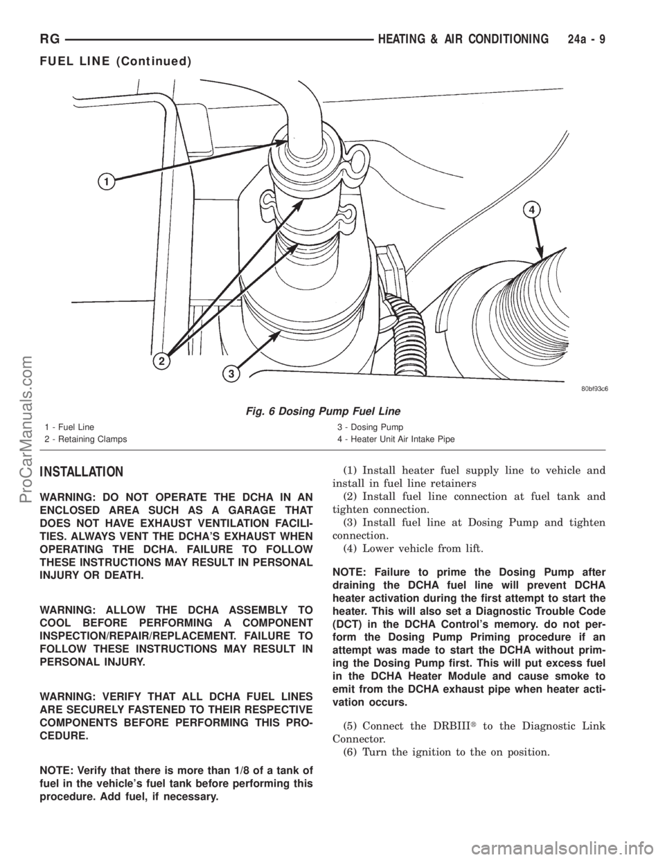
INSTALLATION
WARNING: DO NOT OPERATE THE DCHA IN AN
ENCLOSED AREA SUCH AS A GARAGE THAT
DOES NOT HAVE EXHAUST VENTILATION FACILI-
TIES. ALWAYS VENT THE DCHA'S EXHAUST WHEN
OPERATING THE DCHA. FAILURE TO FOLLOW
THESE INSTRUCTIONS MAY RESULT IN PERSONAL
INJURY OR DEATH.
WARNING: ALLOW THE DCHA ASSEMBLY TO
COOL BEFORE PERFORMING A COMPONENT
INSPECTION/REPAIR/REPLACEMENT. FAILURE TO
FOLLOW THESE INSTRUCTIONS MAY RESULT IN
PERSONAL INJURY.
WARNING: VERIFY THAT ALL DCHA FUEL LINES
ARE SECURELY FASTENED TO THEIR RESPECTIVE
COMPONENTS BEFORE PERFORMING THIS PRO-
CEDURE.
NOTE: Verify that there is more than 1/8 of a tank of
fuel in the vehicle's fuel tank before performing this
procedure. Add fuel, if necessary.(1) Install heater fuel supply line to vehicle and
install in fuel line retainers
(2) Install fuel line connection at fuel tank and
tighten connection.
(3) Install fuel line at Dosing Pump and tighten
connection.
(4) Lower vehicle from lift.
NOTE: Failure to prime the Dosing Pump after
draining the DCHA fuel line will prevent DCHA
heater activation during the first attempt to start the
heater. This will also set a Diagnostic Trouble Code
(DCT) in the DCHA Control's memory. do not per-
form the Dosing Pump Priming procedure if an
attempt was made to start the DCHA without prim-
ing the Dosing Pump first. This will put excess fuel
in the DCHA Heater Module and cause smoke to
emit from the DCHA exhaust pipe when heater acti-
vation occurs.
(5) Connect the DRBIIItto the Diagnostic Link
Connector.
(6) Turn the ignition to the on position.
Fig. 6 Dosing Pump Fuel Line
1 - Fuel Line
2 - Retaining Clamps3 - Dosing Pump
4 - Heater Unit Air Intake Pipe
RGHEATING & AIR CONDITIONING24a-9
FUEL LINE (Continued)
ProCarManuals.com
Page 2285 of 2321
put component, it can verify that the command was
carried out by monitoring specific input signals for
expected changes. For example, when the PCM com-
mands the Idle Air Control (IAC) Motor to a specific
position under certain operating conditions, it expects
to see a specific (target) idle speed (RPM). If it does
not, it stores a DTC.
PCM outputs monitored for functionality include:
²Fuel Injectors
²Ignition Coils
²Torque Converter Clutch Solenoid
²Idle Air Control
²Purge Solenoid
²EGR Solenoid
²LDP Solenoid
²Radiator Fan Control
²Trans Controls
OXYGEN SENSOR (O2S) MONITOR
DESCRIPTIONÐEffective control of exhaust
emissions is achieved by an oxygen feedback system.
The most important element of the feedback system
is the O2S. The O2S is located in the exhaust path.
Once it reaches operating temperature 300É to 350ÉC
(572É to 662ÉF), the sensor generates a voltage that
is inversely proportional to the amount of oxygen in
the exhaust. When there is a large amount of oxygen
in the exhaust caused by a lean condition, the sensor
produces a low voltage, below 450 mV. When the oxy-
gen content is lower, caused by a rich condition, the
sensor produces a higher voltage, above 450mV.
The information obtained by the sensor is used to
calculate the fuel injector pulse width. The PCM is
programmed to maintain the optimum air/fuel ratio.
At this mixture ratio, the catalyst works best to
remove hydrocarbons (HC), carbon monoxide (CO)
and nitrous oxide (NOx) from the exhaust.
The O2S is also the main sensing element for the
EGR, Catalyst and Fuel Monitors.
The O2S may fail in any or all of the following
manners:
²Slow response rate (Big Slope)
²Reduced output voltage (Half Cycle)
²Heater Performance
Slow Response Rate (Big Slope)ÐResponse rate
is the time required for the sensor to switch from
lean to rich signal output once it is exposed to a
richer than optimum A/F mixture or vice versa. As
the PCM adjusts the air/fuel ratio, the sensor must
be able to rapidly detect the change. As the sensor
ages, it could take longer to detect the changes in the
oxygen content of the exhaust gas. The rate of
change that an oxygen sensor experiences is called
'Big Slope'. The PCM checks the oxygen sensor volt-
age in increments of a few milliseconds.Reduced Output Voltage (Half Cycle)ÐThe
output voltage of the O2S ranges from 0 to 1 volt. A
good sensor can easily generate any output voltage in
this range as it is exposed to different concentrations
of oxygen. To detect a shift in the A/F mixture (lean
or rich), the output voltage has to change beyond a
threshold value. A malfunctioning sensor could have
difficulty changing beyond the threshold value. Each
time the voltage signal surpasses the threshold, a
counter is incremented by one. This is called the Half
Cycle Counter.
Heater PerformanceÐThe heater is tested by a
separate monitor. Refer to the Oxygen Sensor Heater
Monitor.
OPERATIONÐAs the Oxygen Sensor signal
switches, the PCM monitors the half cycle and big
slope signals from the oxygen sensor. If during the
test neither counter reaches a predetermined value, a
malfunction is entered and a Freeze Frame is stored.
Only one counter reaching its predetermined value is
needed for the monitor to pass.
The Oxygen Sensor Monitor is a two trip monitor
that is tested only once per trip. When the Oxygen
Sensor fails the test in two consecutive trips, the
MIL is illuminated and a DTC is set. The MIL is
extinguished when the Oxygen Sensor monitor
passes in three consecutive trips. The DTC is erased
from memory after 40 consecutive warm-up cycles
without test failure.
Enabling ConditionsÐThe following conditions
must typically be met for the PCM to run the oxygen
sensor monitor:
²Battery voltage
²Engine temperature
²Engine run time
²Engine run time at a predetermined speed
²Engine run time at a predetermined speed and
throttle opening
²Transmission in gear (automatic only)
²Fuel system in Closed Loop
²Long Term Adaptive (within parameters)
²Power Steering Switch in low PSI (no load)
²Engine at idle
²Fuel level above 15%
²Ambient air temperature
²Barometric pressure
²Engine RPM within acceptable range of desired
idle
²Closed throttle speed
Pending ConditionsÐThe Task Manager typi-
cally does not run the Oxygen Sensor Monitor if over-
lapping monitors are running or the MIL is
illuminated for any of the following:
²Misfire Monitor
²Front Oxygen Sensor and Heater Monitor
²MAP Sensor
25 - 2 EMISSIONS CONTROLRS
EMISSIONS CONTROL (Continued)
ProCarManuals.com
Page 2286 of 2321
²Vehicle Speed Sensor
²Engine Coolant Temperature Sensor
²Throttle Position Sensor
²Engine Controller Self Test Faults
²Cam or Crank Sensor
²Injector and Coil
²Idle Air Control Motor
²EVAP Electrical
²EGR Solenoid Electrical
²Intake Air Temperature
²5 Volt Feed
ConflictÐThe Task Manager does not run the
Oxygen Sensor Monitor if any of the following condi-
tions are present:
²A/C ON (A/C clutch cycling temporarily sus-
pends monitor)
²Purge flow in progress
²Ethanel content learn is takeng place and the
ethenal used once flag is set
SuspendÐThe Task Manager suspends maturing
a fault for the Oxygen Sensor Monitor if an of the fol-
lowing are present:
²Oxygen Sensor Heater Monitor, Priority 1
²Misfire Monitor, Priority 2
OXYGEN SENSOR HEATER MONITOR
DESCRIPTIONÐIf there is an oxygen sensor
(O2S) DTC as well as a O2S heater DTC, the O2S
fault MUST be repaired first. After the O2S fault is
repaired, verify that the heater circuit is operating
correctly.
The voltage readings taken from the O2S are very
temperature sensitive. The readings are not accurate
below 300ÉC. Heating of the O2S is done to allow the
engine controller to shift to closed loop control as
soon as possible. The heating element used to heat
the O2S must be tested to ensure that it is heating
the sensor properly.
The heater element itself is not tested. The sensor
output is used to test the heater by isolating the
effect of the heater element on the O2S output volt-
age from the other effects. The resistance is normally
between 100 ohms and 4.5 megaohms. When oxygen
sensor temperature increases, the resistance in the
internal circuit decreases. The PCM sends a 5 volts
biased signal through the oxygen sensors to ground
this monitoring circuit. As the temperature increases,
resistance decreases and the PCM detects a lower
voltage at the reference signal. Inversely, as the tem-
perature decreases, the resistance increases and the
PCM detects a higher voltage at the reference signal.
The O2S circuit is monitored for a drop in voltage.
OPERATIONÐThe Oxygen Sensor Heater Moni-
tor begins after the ignition has been turned OFF
and the O2 sensors have cooled. The PCM sends a 5
volt bias to the oxygen sensor every 1.6 seconds. ThePCM keeps it biased for 35 ms each time. As the sen-
sor cools down, the resistance increases and the PCM
reads the increase in voltage. Once voltage has
increased to a predetermined amount, higher than
when the test started, the oxygen sensor is cool
enough to test heater operation.
When the oxygen sensor is cool enough, the PCM
energizes the ASD relay. Voltage to the O2 sensor
begins to increase the temperature. As the sensor
temperature increases, the internal resistance
decreases. The PCM continues biasing the 5 volt sig-
nal to the sensor. Each time the signal is biased, the
PCM reads a voltage decrease. When the PCM
detects a voltage decrease of a predetermined value
for several biased pulses, the test passes.
The heater elements are tested each time the
engine is turned OFF if all the enabling conditions
are met. If the monitor fails, the PCM stores a
maturing fault and a Freeze Frame is entered. If two
consecutive tests fail, a DTC is stored. Because the
ignition is OFF, the MIL is illuminated at the begin-
ning of the next key cycle.
Enabling ConditionsÐThe following conditions
must be met for the PCM to run the oxygen sensor
heater test:
²Engine run time of at least 5.1 minutes
²Key OFF power down
²Battery voltage of at least 10 volts
²Sufficient Oxygen Sensor cool down
Pending ConditionsÐThere are not conditions or
situations that prompt conflict or suspension of test-
ing. The oxygen sensor heater test is not run pending
resolution of MIL illumination due to oxygen sensor
failure.
SuspendÐThere are no conditions which exist for
suspending the Heater Monitor.
CATALYST MONITOR
To comply with clean air regulations, vehicles are
equipped with catalytic converters. These converters
reduce the emission of hydrocarbons, oxides of nitro-
gen and carbon monoxide.
Normal vehicle miles or engine misfire can cause a
catalyst to decay. A meltdown of the ceramic core can
cause a reduction of the exhaust passage. This can
increase vehicle emissions and deteriorate engine
performance, driveability and fuel economy.
The catalyst monitor uses dual oxygen sensors
(O2S's) to monitor the efficiency of the converter. The
dual O2S strategy is based on the fact that as a cat-
alyst deteriorates, its oxygen storage capacity and its
efficiency are both reduced. By monitoring the oxy-
gen storage capacity of a catalyst, its efficiency can
be indirectly calculated. The upstream O2S is used to
detect the amount of oxygen in the exhaust gas
before the gas enters the catalytic converter. The
RSEMISSIONS CONTROL25-3
EMISSIONS CONTROL (Continued)
ProCarManuals.com
Page 2287 of 2321
PCM calculates the A/F mixture from the output of
the O2S. A low voltage indicates high oxygen content
(lean mixture). A high voltage indicates a low content
of oxygen (rich mixture).
When the upstream O2S detects a lean condition,
there is an abundance of oxygen in the exhaust gas.
A functioning converter would store this oxygen so it
can use it for the oxidation of HC and CO. As the
converter absorbs the oxygen, there will be a lack of
oxygen downstream of the converter. The output of
the downstream O2S will indicate limited activity in
this condition.
As the converter loses the ability to store oxygen,
the condition can be detected from the behavior of
the downstream O2S. When the efficiency drops, no
chemical reaction takes place. This means the con-
centration of oxygen will be the same downstream as
upstream. The output voltage of the downstream
O2S copies the voltage of the upstream sensor. The
only difference is a time lag (seen by the PCM)
between the switching of the O2S's.
To monitor the system, the number of lean-to-rich
switches of upstream and downstream O2S's is
counted. The ratio of downstream switches to
upstream switches is used to determine whether the
catalyst is operating properly. An effective catalyst
will have fewer downstream switches than it has
upstream switches i.e., a ratio closer to zero. For a
totally ineffective catalyst, this ratio will be one-to-
one, indicating that no oxidation occurs in the device.
The system must be monitored so that when cata-
lyst efficiency deteriorates and exhaust emissions
increase to over the legal limit, the MIL (check
engine lamp) will be illuminated.
Monitor OperationÐTo monitor catalyst effi-
ciency, the PCM expands the rich and lean switch
points of the heated oxygen sensor. With extended
switch points, the air/fuel mixture runs richer and
leaner to overburden the catalytic converter. Once
the test is started, the air/fuel mixture runs rich and
lean and the O2 switches are counted. A switch is
counted when an oxygen sensor signal goes from
below the lean threshold to above the rich threshold.
The number of Rear O2 sensor switches is divided by
the number of Front O2 sensor switches to determine
the switching ratio.
The test runs for 20 seconds. As catalyst efficiency
deteriorated over the life of the vehicle, the switch
rate at the downstream sensor approaches that of the
upstream sensor. If at any point during the test
period the switch ratio reaches a predetermined
value, a counter is incremented by one. The monitor
is enabled to run another test during that trip. When
the test fails three times, the counter increments to
three, a malfunction is entered, and a Freeze Frame
is stored. When the counter increments to three dur-ing the next trip, the code is matured and the MIL is
illuminated. If the test passes the first, no further
testing is conducted during that trip.
The MIL is extinguished after three consecutive
good trips. The good trip criteria for the catalyst
monitor is more stringent than the failure criteria. In
order to pass the test and increment one good trip,
the downstream sensor switch rate must be less than
80% of the upstream rate (60% for manual transmis-
sions). The failure percentages are 90% and 70%
respectively.
Enabling ConditionsÐThe following conditions
must typically be met before the PCM runs the cat-
alyst monitor. Specific times for each parameter may
be different from engine to engine.
²Accumulated drive time
²Enable time
²Ambient air temperature
²Barometric pressure
²Catalyst warm-up counter
²Engine coolant temperature
²Accumulated throttle position sensor
²Vehicle speed
²MAP
²RPM
²Engine in closed loop
²Fuel level
Pending ConditionsÐ
²Misfire DTC
²Front Oxygen Sensor Response
²Front Oxygen Sensor Heater Monitor
²Front Oxygen Sensor Electrical
²Rear Oxygen Sensor Rationality (middle check)
²Rear Oxygen Sensor Heater Monitor
²Rear Oxygen Sensor Electrical
²Fuel System Monitor
²All TPS faults
²All MAP faults
²All ECT sensor faults
²Purge flow solenoid functionality
²Purge flow solenoid electrical
²All PCM self test faults
²All CMP and CKP sensor faults
²All injector and ignition electrical faults
²Idle Air Control (IAC) motor functionality
²Vehicle Speed Sensor
²Brake switch
²Intake air temperature
ConflictÐThe catalyst monitor does not run if any
of the following are conditions are present:
²EGR Monitor in progress
²Fuel system rich intrusive test in progress
²EVAP Monitor in progress
²Time since start is less than 60 seconds
²Low fuel level
²Low ambient air temperature
25 - 4 EMISSIONS CONTROLRS
EMISSIONS CONTROL (Continued)
ProCarManuals.com