2001 DODGE TOWN AND COUNTRY ignition
[x] Cancel search: ignitionPage 1433 of 2321
²TPS
²MAP Sensor
REMOVAL
When servicing throttle body components, always
reassemble components with new O-rings and seals
where applicable. Never use lubricants on O-rings or
seals, damage may result. If assembly of component
is difficult, use water to aid assembly. Use care when
removing hoses to prevent damage to hose or hose
nipple.
(1) Disconnect negative cable from battery.
(2) Remove electrical connector from idle air con-
trol motor.
(3) Remove idle air control motor mounting screws.
(4) Remove motor from throttle body. Ensure the
O-rings is removed with the motor.
INSTALLATION
When servicing throttle body components, always
reassemble components with new O-rings and seals
where applicable. Never use lubricants on O-rings or
seals, damage may result. If assembly of component
is difficult,a light coat of engine oil may be
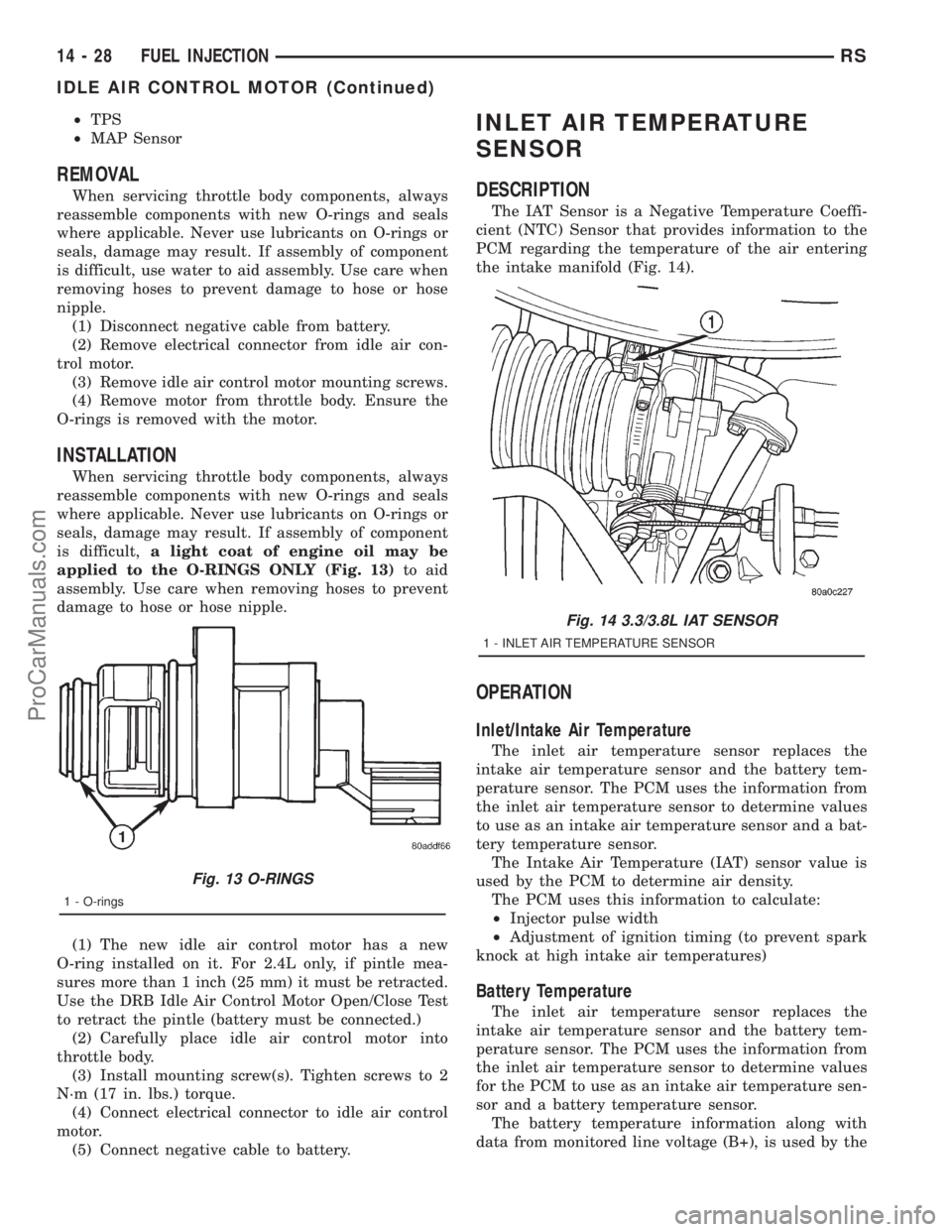
applied to the O-RINGS ONLY (Fig. 13)to aid
assembly. Use care when removing hoses to prevent
damage to hose or hose nipple.
(1) The new idle air control motor has a new
O-ring installed on it. For 2.4L only, if pintle mea-
sures more than 1 inch (25 mm) it must be retracted.
Use the DRB Idle Air Control Motor Open/Close Test
to retract the pintle (battery must be connected.)
(2) Carefully place idle air control motor into
throttle body.
(3) Install mounting screw(s). Tighten screws to 2
N´m (17 in. lbs.) torque.
(4) Connect electrical connector to idle air control
motor.
(5) Connect negative cable to battery.
INLET AIR TEMPERATURE
SENSOR
DESCRIPTION
The IAT Sensor is a Negative Temperature Coeffi-
cient (NTC) Sensor that provides information to the
PCM regarding the temperature of the air entering
the intake manifold (Fig. 14).
OPERATION
Inlet/Intake Air Temperature
The inlet air temperature sensor replaces the
intake air temperature sensor and the battery tem-
perature sensor. The PCM uses the information from
the inlet air temperature sensor to determine values
to use as an intake air temperature sensor and a bat-
tery temperature sensor.
The Intake Air Temperature (IAT) sensor value is
used by the PCM to determine air density.
The PCM uses this information to calculate:
²Injector pulse width
²Adjustment of ignition timing (to prevent spark
knock at high intake air temperatures)
Battery Temperature
The inlet air temperature sensor replaces the
intake air temperature sensor and the battery tem-
perature sensor. The PCM uses the information from
the inlet air temperature sensor to determine values
for the PCM to use as an intake air temperature sen-
sor and a battery temperature sensor.
The battery temperature information along with
data from monitored line voltage (B+), is used by the
Fig. 13 O-RINGS
1 - O-rings
Fig. 14 3.3/3.8L IAT SENSOR
1 - INLET AIR TEMPERATURE SENSOR
14 - 28 FUEL INJECTIONRS
IDLE AIR CONTROL MOTOR (Continued)
ProCarManuals.com
Page 1440 of 2321
OPERATION
The signal represents throttle blade position. As
the position of the throttle blade changes, the resis-
tance of the TPS changes.
The PCM supplies approximately 5 volts to the
TPS. The TPS output voltage (input signal to the
powertrain control module) represents throttle blade
position. The TPS output voltage to the PCM varies
from approximately 0.6 volt at minimum throttle
opening (idle) to a maximum of 4.5 volts at wide open
throttle.
Along with inputs from other sensors, the PCM
uses the TPS input to determine current engine oper-
ating conditions. The PCM also adjusts fuel injectorpulse width and ignition timing based on these
inputs.
REMOVAL
(1) Disconnect the negative battery cable.
(2) Remove the electrical connector from the Inlet
Air Temperature sensor.
(3) Remove the air cleaner box lid. Remove hose
from throttle body.
(4) Disconnect the electrical connector at TPS.
(5) Disconnect the electrical connector at IAC.
(6) Remove the throttle and speed control cables
from throttle body.
(7) Remove 3 mounting bolts from throttle body.
(8) Remove throttle body.
(9) Disconnect the purge vacuum line from the
throttle body.
(10) Remove TPS from throttle body.
INSTALLATION
(1) Install TPS to throttle body.
(2) Disconnect the purge vacuum line from the
throttle body.
(3) Install throttle body.
(4) Install 3 mounting bolts from throttle body.
Tighten bolts.
(5) Install the throttle and speed control cables to
throttle body.
(6) Connect the electrical connector at TPS.
(7) Connect the electrical connector at IAC.
(8) Install the air cleaner box lid. Install hose to
throttle body.
(9) Install the electrical connector to the Inlet Air
Temperature sensor.
(10) Connect the negative battery cable.
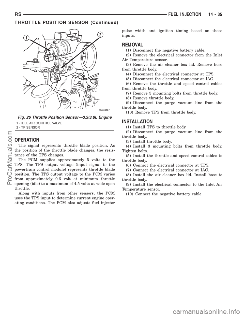
Fig. 26 Throttle Position SensorÐ3.3/3.8L Engine
1 - IDLE AIR CONTROL VALVE
2 - TP SENSOR
RSFUEL INJECTION14-35
THROTTLE POSITION SENSOR (Continued)
ProCarManuals.com
Page 1447 of 2321
FUEL TRANSFER PUMP
DESCRIPTION
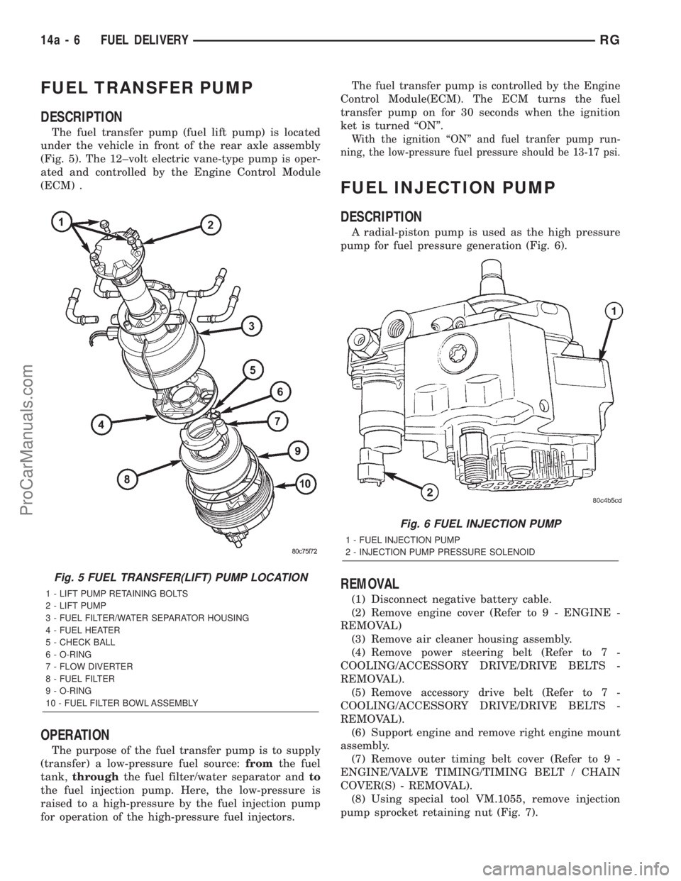
The fuel transfer pump (fuel lift pump) is located
under the vehicle in front of the rear axle assembly
(Fig. 5). The 12±volt electric vane-type pump is oper-
ated and controlled by the Engine Control Module
(ECM) .
OPERATION
The purpose of the fuel transfer pump is to supply
(transfer) a low-pressure fuel source:fromthe fuel
tank,throughthe fuel filter/water separator andto
the fuel injection pump. Here, the low-pressure is
raised to a high-pressure by the fuel injection pump
for operation of the high-pressure fuel injectors.The fuel transfer pump is controlled by the Engine
Control Module(ECM). The ECM turns the fuel
transfer pump on for 30 seconds when the ignition
ket is turned ªONº.
With the ignition ªONº and fuel tranfer pump run-
ning, the low-pressure fuel pressure should be 13-17 psi.
FUEL INJECTION PUMP
DESCRIPTION
A radial-piston pump is used as the high pressure
pump for fuel pressure generation (Fig. 6).
REMOVAL
(1) Disconnect negative battery cable.
(2) Remove engine cover (Refer to 9 - ENGINE -
REMOVAL)
(3) Remove air cleaner housing assembly.
(4) Remove power steering belt (Refer to 7 -
COOLING/ACCESSORY DRIVE/DRIVE BELTS -
REMOVAL).
(5) Remove accessory drive belt (Refer to 7 -
COOLING/ACCESSORY DRIVE/DRIVE BELTS -
REMOVAL).
(6) Support engine and remove right engine mount
assembly.
(7) Remove outer timing belt cover (Refer to 9 -
ENGINE/VALVE TIMING/TIMING BELT / CHAIN
COVER(S) - REMOVAL).
(8) Using special tool VM.1055, remove injection
pump sprocket retaining nut (Fig. 7).
Fig. 5 FUEL TRANSFER(LIFT) PUMP LOCATION
1 - LIFT PUMP RETAINING BOLTS
2 - LIFT PUMP
3 - FUEL FILTER/WATER SEPARATOR HOUSING
4 - FUEL HEATER
5 - CHECK BALL
6 - O-RING
7 - FLOW DIVERTER
8 - FUEL FILTER
9 - O-RING
10 - FUEL FILTER BOWL ASSEMBLY
Fig. 6 FUEL INJECTION PUMP
1 - FUEL INJECTION PUMP
2 - INJECTION PUMP PRESSURE SOLENOID
14a - 6 FUEL DELIVERYRG
ProCarManuals.com
Page 1450 of 2321
(12) Install accessory drive belt (Refer to 7 -
COOLING/ACCESSORY DRIVE/DRIVE BELTS -
INSTALLATION).
(13) Install power steering belt (Refer to 7 -
COOLING/ACCESSORY DRIVE/DRIVE BELTS -
INSTALLATION).
(14) Install air cleaner housing assembly.
(15) Install engine cover (Refer to 9 - ENGINE -
INSTALLATION).
(16) Connect negative battery cable.
WATER IN FUEL SENSOR
DESCRIPTION
The WIF sensor is located in the bowl assembly of
the fuel filter/water separator.
OPERATION
The sensor sends an input to the Engine Control
Module (ECM) when it senses water in the fuel filter/
water separator. As the water level in the filter/sep-
arator increases, the resistance across the WIF
sensor decreases. This decrease in resistance is sent
as a signal to the ECM and compared to a high
water standard value. Once the value reaches 30 to
40 kilohms, the ECM will activate the water-in-fuel
warning lamp through CCD bus circuits. This all
takes place when the ignition key is initially put in
the ON position. The ECM continues to monitor the
input at the end of the intake manifold air heater
post-heat cycle.
RGFUEL DELIVERY14a-9
FUEL INJECTION PUMP (Continued)
ProCarManuals.com
Page 1467 of 2321
COLUMN
TABLE OF CONTENTS
page page
COLUMN
DESCRIPTION...........................10
WARNING..............................10
DIAGNOSIS AND TESTING.................12
STEERING COLUMN....................12
REMOVAL..............................12
INSTALLATION...........................13
SPECIFICATIONS........................14
KEY/LOCK CYLINDER
DESCRIPTION...........................14OPERATION.............................14
REMOVAL..............................14
INSTALLATION...........................14
GEAR SHIFT LEVER
REMOVAL..............................15
INSTALLATION...........................15
SHROUD
REMOVAL..............................16
INSTALLATION...........................16
COLUMN
DESCRIPTION - STEERING COLUMN
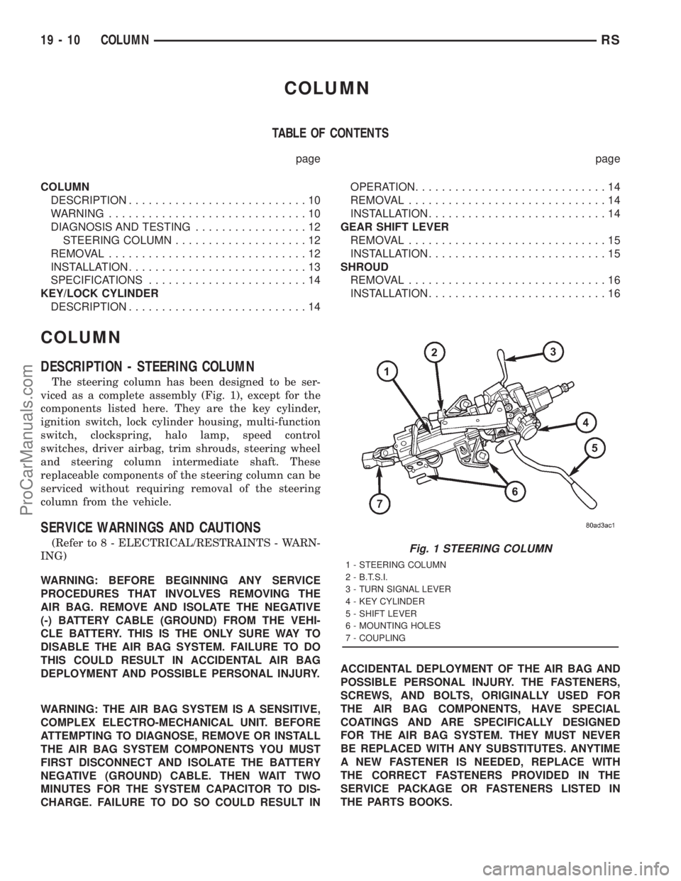
The steering column has been designed to be ser-
viced as a complete assembly (Fig. 1), except for the
components listed here. They are the key cylinder,
ignition switch, lock cylinder housing, multi-function
switch, clockspring, halo lamp, speed control
switches, driver airbag, trim shrouds, steering wheel
and steering column intermediate shaft. These
replaceable components of the steering column can be
serviced without requiring removal of the steering
column from the vehicle.
SERVICE WARNINGS AND CAUTIONS
(Refer to 8 - ELECTRICAL/RESTRAINTS - WARN-
ING)
WARNING: BEFORE BEGINNING ANY SERVICE
PROCEDURES THAT INVOLVES REMOVING THE
AIR BAG. REMOVE AND ISOLATE THE NEGATIVE
(-) BATTERY CABLE (GROUND) FROM THE VEHI-
CLE BATTERY. THIS IS THE ONLY SURE WAY TO
DISABLE THE AIR BAG SYSTEM. FAILURE TO DO
THIS COULD RESULT IN ACCIDENTAL AIR BAG
DEPLOYMENT AND POSSIBLE PERSONAL INJURY.
WARNING: THE AIR BAG SYSTEM IS A SENSITIVE,
COMPLEX ELECTRO-MECHANICAL UNIT. BEFORE
ATTEMPTING TO DIAGNOSE, REMOVE OR INSTALL
THE AIR BAG SYSTEM COMPONENTS YOU MUST
FIRST DISCONNECT AND ISOLATE THE BATTERY
NEGATIVE (GROUND) CABLE. THEN WAIT TWO
MINUTES FOR THE SYSTEM CAPACITOR TO DIS-
CHARGE. FAILURE TO DO SO COULD RESULT INACCIDENTAL DEPLOYMENT OF THE AIR BAG AND
POSSIBLE PERSONAL INJURY. THE FASTENERS,
SCREWS, AND BOLTS, ORIGINALLY USED FOR
THE AIR BAG COMPONENTS, HAVE SPECIAL
COATINGS AND ARE SPECIFICALLY DESIGNED
FOR THE AIR BAG SYSTEM. THEY MUST NEVER
BE REPLACED WITH ANY SUBSTITUTES. ANYTIME
A NEW FASTENER IS NEEDED, REPLACE WITH
THE CORRECT FASTENERS PROVIDED IN THE
SERVICE PACKAGE OR FASTENERS LISTED IN
THE PARTS BOOKS.Fig. 1 STEERING COLUMN
1 - STEERING COLUMN
2 - B.T.S.I.
3 - TURN SIGNAL LEVER
4 - KEY CYLINDER
5 - SHIFT LEVER
6 - MOUNTING HOLES
7 - COUPLING
19 - 10 COLUMNRS
ProCarManuals.com
Page 1469 of 2321
WARNING: SAFETY GOGGLES SHOULD BE WORN
AT ALL TIMES WHEN WORKING ON STEERING
COLUMNS.
CAUTION: Disconnect negative (ground) cable from
the battery before servicing any column compo-
nent.
CAUTION: Do not attempt to remove the pivot pins
to disassemble the tilting mechanism. Damage will
occur.
DIAGNOSIS AND TESTING
For diagnosis of conditions relating to the steering
column (Refer to 19 - STEERING - DIAGNOSIS AND
TESTING) and (Refer to 19 - STEERING - DIAGNO-
SIS AND TESTING).
REMOVAL
To service the steering wheel components or the
airbag (Refer to 8 - ELECTRICAL/RESTRAINTS/
DRIVER AIRBAG - REMOVAL). Follow all WARN-
INGS AND CAUTIONS.
(1) Make sure the front wheels of the vehicle are
in the STRAIGHT AHEAD position before beginning
the column removal procedure.
(2) Disconnect negative (ground) cable from the
battery and isolate cable from battery terminal.
(3) Remove the lower shroud (Refer to 19 -
STEERING/COLUMN/LOWER SHROUD - REMOV-
AL).
(4) Remove the traction off switch.
(5) Remove the upper shroud.
(6) Remove the cluster trim bezel (Refer to 23 -
BODY/INSTRUMENT PANEL/CLUSTER BEZEL -
REMOVAL).(7) Remove the knee blocker (Refer to 23 - BODY/
INSTRUMENT PANEL/STEERING COLUMN
OPENING COVER - REMOVAL).
(8) Remove the parking brake handle link.
(9) Remove the knee blocker reinforcement (Refer
to 23 - BODY/INSTRUMENT PANEL/KNEE
BLOCKER - REMOVAL).
(10) Remove the airbag (Refer to 8 - ELECTRI-
CAL/RESTRAINTS/DRIVER AIRBAG - REMOVAL).
(11) Remove the steering wheel retaining nut.
(12) Remove the vibration damper weight.
(13) Remove the steering wheel (Refer to 19 -
STEERING/COLUMN/STEERING WHEEL -
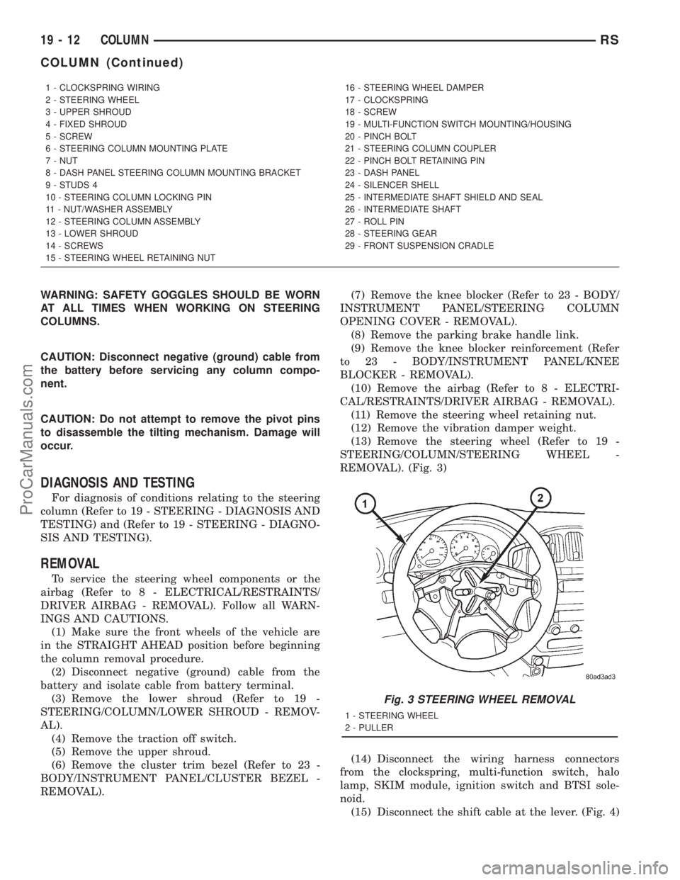
REMOVAL). (Fig. 3)
(14) Disconnect the wiring harness connectors
from the clockspring, multi-function switch, halo
lamp, SKIM module, ignition switch and BTSI sole-
noid.
(15) Disconnect the shift cable at the lever. (Fig. 4)
1 - CLOCKSPRING WIRING
2 - STEERING WHEEL
3 - UPPER SHROUD
4 - FIXED SHROUD
5 - SCREW
6 - STEERING COLUMN MOUNTING PLATE
7 - NUT
8 - DASH PANEL STEERING COLUMN MOUNTING BRACKET
9 - STUDS 4
10 - STEERING COLUMN LOCKING PIN
11 - NUT/WASHER ASSEMBLY
12 - STEERING COLUMN ASSEMBLY
13 - LOWER SHROUD
14 - SCREWS
15 - STEERING WHEEL RETAINING NUT16 - STEERING WHEEL DAMPER
17 - CLOCKSPRING
18 - SCREW
19 - MULTI-FUNCTION SWITCH MOUNTING/HOUSING
20 - PINCH BOLT
21 - STEERING COLUMN COUPLER
22 - PINCH BOLT RETAINING PIN
23 - DASH PANEL
24 - SILENCER SHELL
25 - INTERMEDIATE SHAFT SHIELD AND SEAL
26 - INTERMEDIATE SHAFT
27 - ROLL PIN
28 - STEERING GEAR
29 - FRONT SUSPENSION CRADLE
Fig. 3 STEERING WHEEL REMOVAL
1 - STEERING WHEEL
2 - PULLER
19 - 12 COLUMNRS
COLUMN (Continued)
ProCarManuals.com
Page 1470 of 2321
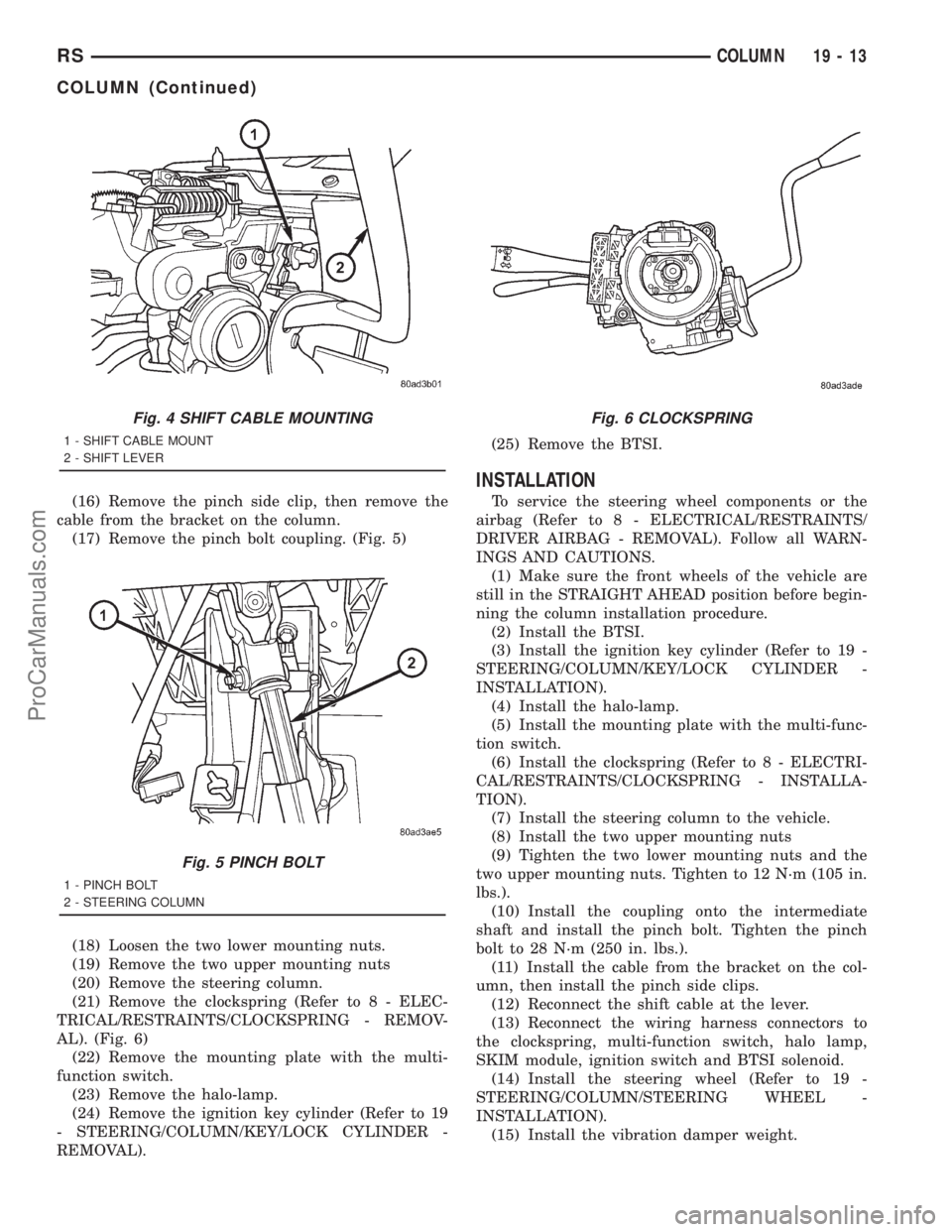
(16) Remove the pinch side clip, then remove the
cable from the bracket on the column.
(17) Remove the pinch bolt coupling. (Fig. 5)
(18) Loosen the two lower mounting nuts.
(19) Remove the two upper mounting nuts
(20) Remove the steering column.
(21) Remove the clockspring (Refer to 8 - ELEC-
TRICAL/RESTRAINTS/CLOCKSPRING - REMOV-
AL). (Fig. 6)
(22) Remove the mounting plate with the multi-
function switch.
(23) Remove the halo-lamp.
(24) Remove the ignition key cylinder (Refer to 19
- STEERING/COLUMN/KEY/LOCK CYLINDER -
REMOVAL).(25) Remove the BTSI.
INSTALLATION
To service the steering wheel components or the
airbag (Refer to 8 - ELECTRICAL/RESTRAINTS/
DRIVER AIRBAG - REMOVAL). Follow all WARN-
INGS AND CAUTIONS.
(1) Make sure the front wheels of the vehicle are
still in the STRAIGHT AHEAD position before begin-
ning the column installation procedure.
(2) Install the BTSI.
(3) Install the ignition key cylinder (Refer to 19 -
STEERING/COLUMN/KEY/LOCK CYLINDER -
INSTALLATION).
(4) Install the halo-lamp.
(5) Install the mounting plate with the multi-func-
tion switch.
(6) Install the clockspring (Refer to 8 - ELECTRI-
CAL/RESTRAINTS/CLOCKSPRING - INSTALLA-
TION).
(7) Install the steering column to the vehicle.
(8) Install the two upper mounting nuts
(9) Tighten the two lower mounting nuts and the
two upper mounting nuts. Tighten to 12 N´m (105 in.
lbs.).
(10) Install the coupling onto the intermediate
shaft and install the pinch bolt. Tighten the pinch
bolt to 28 N´m (250 in. lbs.).
(11) Install the cable from the bracket on the col-
umn, then install the pinch side clips.
(12) Reconnect the shift cable at the lever.
(13) Reconnect the wiring harness connectors to
the clockspring, multi-function switch, halo lamp,
SKIM module, ignition switch and BTSI solenoid.
(14) Install the steering wheel (Refer to 19 -
STEERING/COLUMN/STEERING WHEEL -
INSTALLATION).
(15) Install the vibration damper weight.
Fig. 4 SHIFT CABLE MOUNTING
1 - SHIFT CABLE MOUNT
2 - SHIFT LEVER
Fig. 5 PINCH BOLT
1 - PINCH BOLT
2 - STEERING COLUMN
Fig. 6 CLOCKSPRING
RSCOLUMN19-13
COLUMN (Continued)
ProCarManuals.com
Page 1471 of 2321
(16) Install the steering wheel retaining nut.
Tighten the nut to 61 N´m (45 ft. lbs.)
(17) Install the airbag (Refer to 8 - ELECTRICAL/
RESTRAINTS/DRIVER AIRBAG - INSTALLATION).
(18) Install the knee blocker reinforcement (Refer
to 23 - BODY/INSTRUMENT PANEL/KNEE
BLOCKER - INSTALLATION).
(19) Install the parking brake handle link.
(20) Install the knee blocker (Refer to 23 - BODY/
INSTRUMENT PANEL/STEERING COLUMN
OPENING COVER - INSTALLATION).
(21) Install the cluster trim bezel (Refer to 23 -
BODY/INSTRUMENT PANEL/CLUSTER BEZEL -
INSTALLATION).
(22) Install the upper shroud (Refer to 19 -
STEERING/COLUMN/LOWER SHROUD - INSTAL-
LATION).
(23) Install the traction off switch.
(24) Install the lower shroud.
SPECIFICATIONS
COLUMN TORQUE
DESCRIPTION N´mFt.
Lbs.In.
Lbs.
Steering Wheel Retaining
Nut61 45 Ð
Steering Column Mounting
Bracket Attaching Nuts12 Ð 105
Steering Column Coupling
Pinch Bolt28 Ð 250
Steering Column Airbag
Module Attaching Nuts11 Ð 100
KEY/LOCK CYLINDER
DESCRIPTION
The lock cylinder is inserted in the end of the
housing opposite the ignition switch.
OPERATION
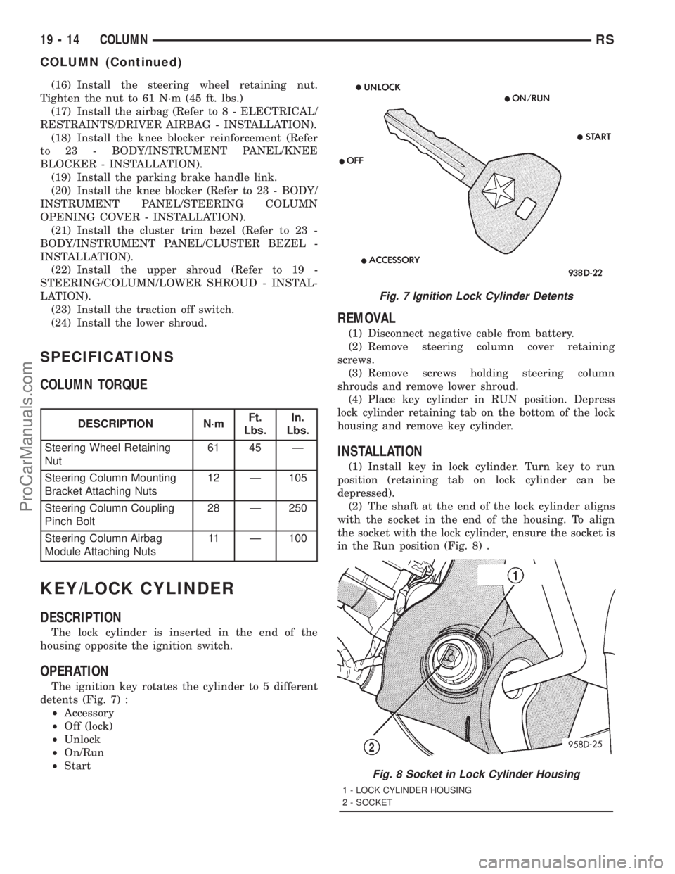
The ignition key rotates the cylinder to 5 different
detents (Fig. 7) :
²Accessory
²Off (lock)
²Unlock
²On/Run
²Start
REMOVAL
(1) Disconnect negative cable from battery.
(2) Remove steering column cover retaining
screws.
(3) Remove screws holding steering column
shrouds and remove lower shroud.
(4) Place key cylinder in RUN position. Depress
lock cylinder retaining tab on the bottom of the lock
housing and remove key cylinder.
INSTALLATION
(1) Install key in lock cylinder. Turn key to run
position (retaining tab on lock cylinder can be
depressed).
(2) The shaft at the end of the lock cylinder aligns
with the socket in the end of the housing. To align
the socket with the lock cylinder, ensure the socket is
in the Run position (Fig. 8) .
Fig. 7 Ignition Lock Cylinder Detents
Fig. 8 Socket in Lock Cylinder Housing
1 - LOCK CYLINDER HOUSING
2 - SOCKET
19 - 14 COLUMNRS
COLUMN (Continued)
ProCarManuals.com