2001 DODGE TOWN AND COUNTRY ignition
[x] Cancel search: ignitionPage 1091 of 2321
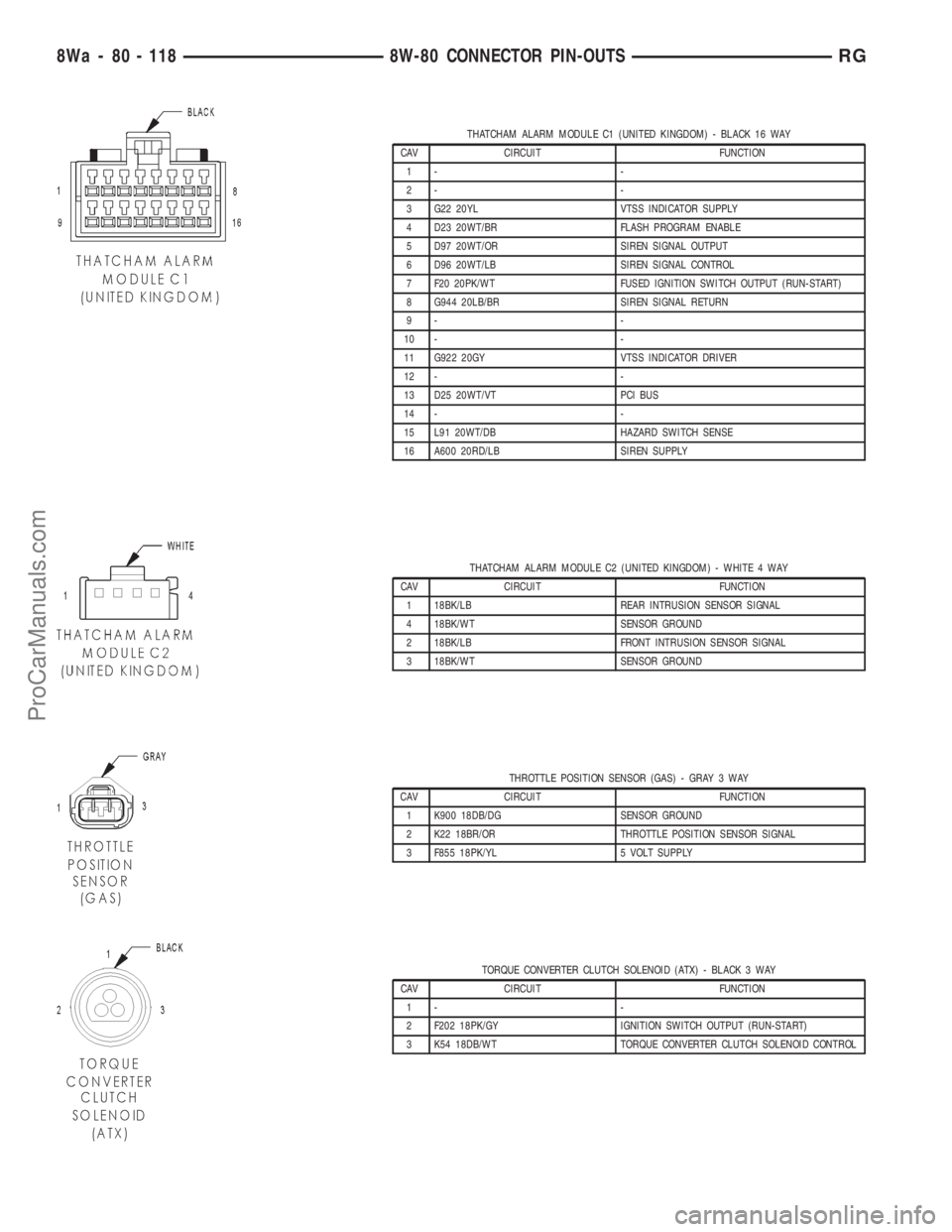
THATCHAM ALARM MODULE C1 (UNITED KINGDOM) - BLACK 16 WAY
CAV CIRCUIT FUNCTION
1- -
2- -
3 G22 20YL VTSS INDICATOR SUPPLY
4 D23 20WT/BR FLASH PROGRAM ENABLE
5 D97 20WT/OR SIREN SIGNAL OUTPUT
6 D96 20WT/LB SIREN SIGNAL CONTROL
7 F20 20PK/WT FUSED IGNITION SWITCH OUTPUT (RUN-START)
8 G944 20LB/BR SIREN SIGNAL RETURN
9- -
10 - -
11 G922 20GY VTSS INDICATOR DRIVER
12 - -
13 D25 20WT/VT PCI BUS
14 - -
15 L91 20WT/DB HAZARD SWITCH SENSE
16 A600 20RD/LB SIREN SUPPLY
THATCHAM ALARM MODULE C2 (UNITED KINGDOM) - WHITE 4 WAY
CAV CIRCUIT FUNCTION
1 18BK/LB REAR INTRUSION SENSOR SIGNAL
4 18BK/WT SENSOR GROUND
2 18BK/LB FRONT INTRUSION SENSOR SIGNAL
3 18BK/WT SENSOR GROUND
THROTTLE POSITION SENSOR (GAS) - GRAY 3 WAY
CAV CIRCUIT FUNCTION
1 K900 18DB/DG SENSOR GROUND
2 K22 18BR/OR THROTTLE POSITION SENSOR SIGNAL
3 F855 18PK/YL 5 VOLT SUPPLY
TORQUE CONVERTER CLUTCH SOLENOID (ATX) - BLACK 3 WAY
CAV CIRCUIT FUNCTION
1- -
2 F202 18PK/GY IGNITION SWITCH OUTPUT (RUN-START)
3 K54 18DB/WT TORQUE CONVERTER CLUTCH SOLENOID CONTROL
8Wa - 80 - 118 8W-80 CONNECTOR PIN-OUTSRG
ProCarManuals.com
Page 1092 of 2321
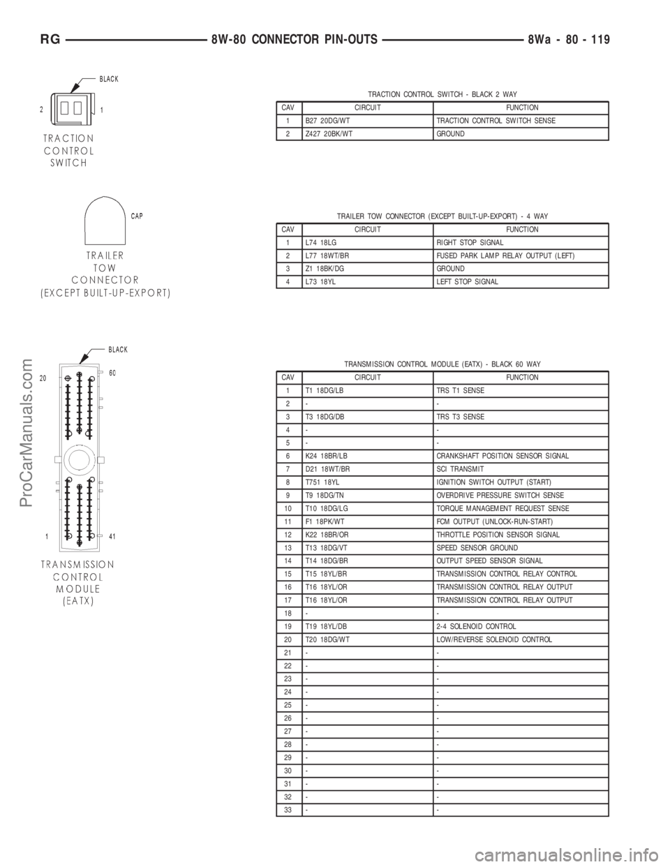
TRACTION CONTROL SWITCH - BLACK 2 WAY
CAV CIRCUIT FUNCTION
1 B27 20DG/WT TRACTION CONTROL SWITCH SENSE
2 Z427 20BK/WT GROUND
TRAILER TOW CONNECTOR (EXCEPT BUILT-UP-EXPORT)-4WAY
CAV CIRCUIT FUNCTION
1 L74 18LG RIGHT STOP SIGNAL
2 L77 18WT/BR FUSED PARK LAMP RELAY OUTPUT (LEFT)
3 Z1 18BK/DG GROUND
4 L73 18YL LEFT STOP SIGNAL
TRANSMISSION CONTROL MODULE (EATX) - BLACK 60 WAY
CAV CIRCUIT FUNCTION
1 T1 18DG/LB TRS T1 SENSE
2- -
3 T3 18DG/DB TRS T3 SENSE
4- -
5- -
6 K24 18BR/LB CRANKSHAFT POSITION SENSOR SIGNAL
7 D21 18WT/BR SCI TRANSMIT
8 T751 18YL IGNITION SWITCH OUTPUT (START)
9 T9 18DG/TN OVERDRIVE PRESSURE SWITCH SENSE
10 T10 18DG/LG TORQUE MANAGEMENT REQUEST SENSE
11 F1 18PK/WT FCM OUTPUT (UNLOCK-RUN-START)
12 K22 18BR/OR THROTTLE POSITION SENSOR SIGNAL
13 T13 18DG/VT SPEED SENSOR GROUND
14 T14 18DG/BR OUTPUT SPEED SENSOR SIGNAL
15 T15 18YL/BR TRANSMISSION CONTROL RELAY CONTROL
16 T16 18YL/OR TRANSMISSION CONTROL RELAY OUTPUT
17 T16 18YL/OR TRANSMISSION CONTROL RELAY OUTPUT
18 - -
19 T19 18YL/DB 2-4 SOLENOID CONTROL
20 T20 18DG/WT LOW/REVERSE SOLENOID CONTROL
21 - -
22 - -
23 - -
24 - -
25 - -
26 - -
27 - -
28 - -
29 - -
30 - -
31 - -
32 - -
33 - -
RG8W-80 CONNECTOR PIN-OUTS8Wa - 80 - 119
ProCarManuals.com
Page 1094 of 2321
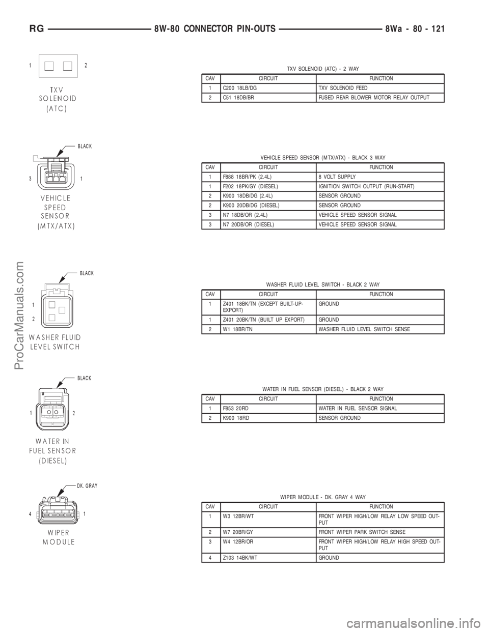
TXV SOLENOID (ATC)-2WAY
CAV CIRCUIT FUNCTION
1 C200 18LB/DG TXV SOLENOID FEED
2 C51 18DB/BR FUSED REAR BLOWER MOTOR RELAY OUTPUT
VEHICLE SPEED SENSOR (MTX/ATX) - BLACK 3 WAY
CAV CIRCUIT FUNCTION
1 F888 18BR/PK (2.4L) 8 VOLT SUPPLY
1 F202 18PK/GY (DIESEL) IGNITION SWITCH OUTPUT (RUN-START)
2 K900 18DB/DG (2.4L) SENSOR GROUND
2 K900 20DB/DG (DIESEL) SENSOR GROUND
3 N7 18DB/OR (2.4L) VEHICLE SPEED SENSOR SIGNAL
3 N7 20DB/OR (DIESEL) VEHICLE SPEED SENSOR SIGNAL
WASHER FLUID LEVEL SWITCH - BLACK 2 WAY
CAV CIRCUIT FUNCTION
1 Z401 18BK/TN (EXCEPT BUILT-UP-
EXPORT)GROUND
1 Z401 20BK/TN (BUILT UP EXPORT) GROUND
2 W1 18BR/TN WASHER FLUID LEVEL SWITCH SENSE
WATER IN FUEL SENSOR (DIESEL) - BLACK 2 WAY
CAV CIRCUIT FUNCTION
1 F853 20RD WATER IN FUEL SENSOR SIGNAL
2 K900 18RD SENSOR GROUND
WIPER MODULE - DK. GRAY 4 WAY
CAV CIRCUIT FUNCTION
1 W3 12BR/WT FRONT WIPER HIGH/LOW RELAY LOW SPEED OUT-
PUT
2 W7 20BR/GY FRONT WIPER PARK SWITCH SENSE
3 W4 12BR/OR FRONT WIPER HIGH/LOW RELAY HIGH SPEED OUT-
PUT
4 Z103 14BK/WT GROUND
RG8W-80 CONNECTOR PIN-OUTS8Wa - 80 - 121
ProCarManuals.com
Page 1100 of 2321
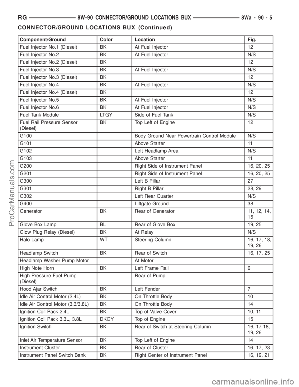
Component/Ground Color Location Fig.
Fuel Injector No.1 (Diesel) BK At Fuel Injector 12
Fuel Injector No.2 BK At Fuel Injector N/S
Fuel Injector No.2 (Diesel) BK 12
Fuel Injector No.3 BK At Fuel Injector N/S
Fuel Injector No.3 (Diesel) BK 12
Fuel Injector No.4 BK At Fuel Injector N/S
Fuel Injector No.4 (Diesel) BK 12
Fuel Injector No.5 BK At Fuel Injector N/S
Fuel Injector No.6 BK At Fuel Injector N/S
Fuel Tank Module LTGY Side of Fuel Tank N/S
Fuel Rail Pressure Sensor
(Diesel)BK Top Left of Engine 12
G100 Body Ground Near Powertrain Control Module N/S
G101 Above Starter 11
G102 Left Headlamp Area N/S
G103 Above Starter 11
G200 Right Side of Instrument Panel 16, 20, 25
G201 Right Side of Instrument Panel 16, 20, 25
G300 Left B Pillar 27
G301 Right B Pillar 28, 29
G302 Left Rear Quarter N/S
G400 Liftgate Ground 38
Generator BK Rear of Generator 11, 12, 14,
15
Glove Box Lamp BL Rear of Glove Box 19, 25
Glow Plug Relay (Diesel) BK At Relay N/S
Halo Lamp WT Steering Column 16, 17, 18,
19, 26
Headlamp Switch BK Rear of Switch 16, 17, 25
Headlamp Washer Pump Motor At Motor
High Note Horn BK Left Frame Rail 6
High Pressure Fuel Pump
(Diesel)Rear of Pump
Hood Ajar Switch BK Left Fender 7
Idle Air Control Motor (2.4L) BK On Throttle Body 10
Idle Air Control Motor (3.3/3.8L) BK On Throttle Body 14
Ignition Coil Pack 2.4L BK Top of Valve Cover 10, 11
Ignition Coil Pack 3.3L, 3.8L DKGY Top of Engine 15
Ignition Switch BK Rear of Switch at Steering Column 16, 17 18,
19, 26
Inlet Air Temperature Sensor BK Top Left of Engine 14
Instrument Cluster BK Rear of Cluster 16, 17, 23
Instrument Panel Switch Bank BK Right Center of Instrument Panel 16, 19, 21
RG8W-90 CONNECTOR/GROUND LOCATIONS BUX8Wa-90-5
CONNECTOR/GROUND LOCATIONS BUX (Continued)
ProCarManuals.com
Page 1138 of 2321
8W-95 SPLICE LOCATIONS BUX
TABLE OF CONTENTS
page
SPLICE LOCATIONS BUX
DESCRIPTION............................1
SPLICE LOCATIONS BUX
DESCRIPTION
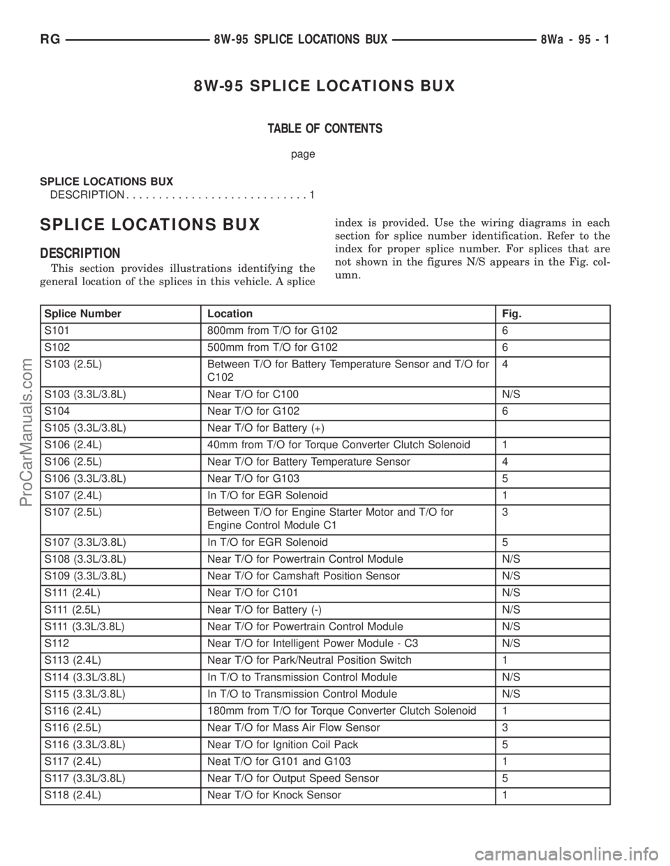
This section provides illustrations identifying the
general location of the splices in this vehicle. A spliceindex is provided. Use the wiring diagrams in each
section for splice number identification. Refer to the
index for proper splice number. For splices that are
not shown in the figures N/S appears in the Fig. col-
umn.
Splice Number Location Fig.
S101 800mm from T/O for G102 6
S102 500mm from T/O for G102 6
S103 (2.5L) Between T/O for Battery Temperature Sensor and T/O for
C1024
S103 (3.3L/3.8L) Near T/O for C100 N/S
S104 Near T/O for G102 6
S105 (3.3L/3.8L) Near T/O for Battery (+)
S106 (2.4L) 40mm from T/O for Torque Converter Clutch Solenoid 1
S106 (2.5L) Near T/O for Battery Temperature Sensor 4
S106 (3.3L/3.8L) Near T/O for G103 5
S107 (2.4L) In T/O for EGR Solenoid 1
S107 (2.5L) Between T/O for Engine Starter Motor and T/O for
Engine Control Module C13
S107 (3.3L/3.8L) In T/O for EGR Solenoid 5
S108 (3.3L/3.8L) Near T/O for Powertrain Control Module N/S
S109 (3.3L/3.8L) Near T/O for Camshaft Position Sensor N/S
S111 (2.4L) Near T/O for C101 N/S
S111 (2.5L) Near T/O for Battery (-) N/S
S111 (3.3L/3.8L) Near T/O for Powertrain Control Module N/S
S112 Near T/O for Intelligent Power Module - C3 N/S
S113 (2.4L) Near T/O for Park/Neutral Position Switch 1
S114 (3.3L/3.8L) In T/O to Transmission Control Module N/S
S115 (3.3L/3.8L) In T/O to Transmission Control Module N/S
S116 (2.4L) 180mm from T/O for Torque Converter Clutch Solenoid 1
S116 (2.5L) Near T/O for Mass Air Flow Sensor 3
S116 (3.3L/3.8L) Near T/O for Ignition Coil Pack 5
S117 (2.4L) Neat T/O for G101 and G103 1
S117 (3.3L/3.8L) Near T/O for Output Speed Sensor 5
S118 (2.4L) Near T/O for Knock Sensor 1
RG8W-95 SPLICE LOCATIONS BUX8Wa-95-1
ProCarManuals.com
Page 1160 of 2321
ENGINE 2.4L
DESCRIPTION
The 2.4 Liter (148 cu. in.) in-line four cylinder
engine is a double over head camshaft with hydraulic
lifters and four valve per cylinder design. The engine
is free-wheeling; meaning it has provisions for piston-
to-valve clearance. However valve-to-valve interfer-
ence can occur, if camshafts are rotated
independently.
The cylinders are numbered from front of the
engine to the rear. The firing order is 1±3±4±2.
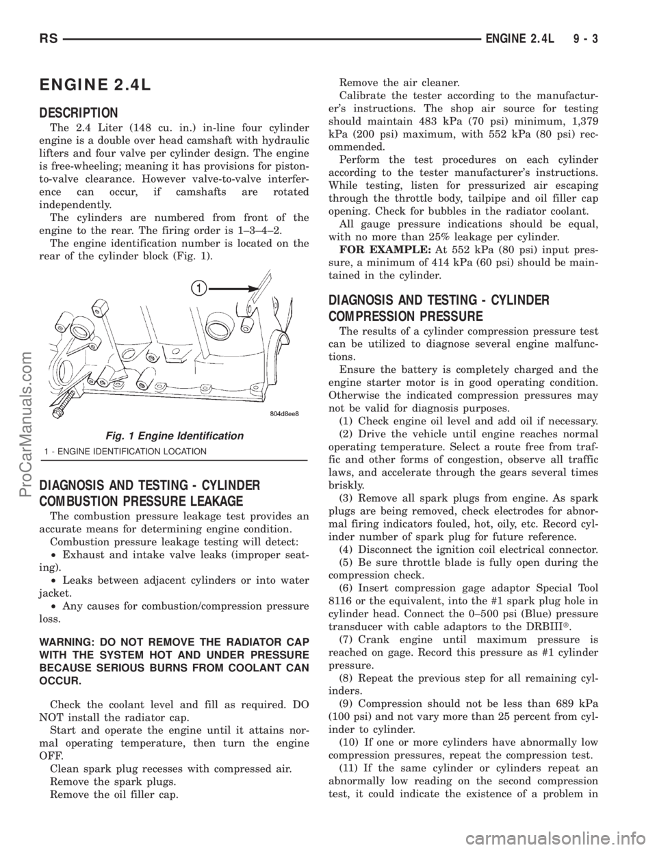
The engine identification number is located on the
rear of the cylinder block (Fig. 1).
DIAGNOSIS AND TESTING - CYLINDER
COMBUSTION PRESSURE LEAKAGE
The combustion pressure leakage test provides an
accurate means for determining engine condition.
Combustion pressure leakage testing will detect:
²Exhaust and intake valve leaks (improper seat-
ing).
²Leaks between adjacent cylinders or into water
jacket.
²Any causes for combustion/compression pressure
loss.
WARNING: DO NOT REMOVE THE RADIATOR CAP
WITH THE SYSTEM HOT AND UNDER PRESSURE
BECAUSE SERIOUS BURNS FROM COOLANT CAN
OCCUR.
Check the coolant level and fill as required. DO
NOT install the radiator cap.
Start and operate the engine until it attains nor-
mal operating temperature, then turn the engine
OFF.
Clean spark plug recesses with compressed air.
Remove the spark plugs.
Remove the oil filler cap.Remove the air cleaner.
Calibrate the tester according to the manufactur-
er's instructions. The shop air source for testing
should maintain 483 kPa (70 psi) minimum, 1,379
kPa (200 psi) maximum, with 552 kPa (80 psi) rec-
ommended.
Perform the test procedures on each cylinder
according to the tester manufacturer's instructions.
While testing, listen for pressurized air escaping
through the throttle body, tailpipe and oil filler cap
opening. Check for bubbles in the radiator coolant.
All gauge pressure indications should be equal,
with no more than 25% leakage per cylinder.
FOR EXAMPLE:At 552 kPa (80 psi) input pres-
sure, a minimum of 414 kPa (60 psi) should be main-
tained in the cylinder.
DIAGNOSIS AND TESTING - CYLINDER
COMPRESSION PRESSURE
The results of a cylinder compression pressure test
can be utilized to diagnose several engine malfunc-
tions.
Ensure the battery is completely charged and the
engine starter motor is in good operating condition.
Otherwise the indicated compression pressures may
not be valid for diagnosis purposes.
(1) Check engine oil level and add oil if necessary.
(2) Drive the vehicle until engine reaches normal
operating temperature. Select a route free from traf-
fic and other forms of congestion, observe all traffic
laws, and accelerate through the gears several times
briskly.
(3) Remove all spark plugs from engine. As spark
plugs are being removed, check electrodes for abnor-
mal firing indicators fouled, hot, oily, etc. Record cyl-
inder number of spark plug for future reference.
(4) Disconnect the ignition coil electrical connector.
(5) Be sure throttle blade is fully open during the
compression check.
(6) Insert compression gage adaptor Special Tool
8116 or the equivalent, into the #1 spark plug hole in
cylinder head. Connect the 0±500 psi (Blue) pressure
transducer with cable adaptors to the DRBIIIt.
(7) Crank engine until maximum pressure is
reached on gage. Record this pressure as #1 cylinder
pressure.
(8) Repeat the previous step for all remaining cyl-
inders.
(9) Compression should not be less than 689 kPa
(100 psi) and not vary more than 25 percent from cyl-
inder to cylinder.
(10) If one or more cylinders have abnormally low
compression pressures, repeat the compression test.
(11) If the same cylinder or cylinders repeat an
abnormally low reading on the second compression
test, it could indicate the existence of a problem in
Fig. 1 Engine Identification
1 - ENGINE IDENTIFICATION LOCATION
RSENGINE 2.4L9-3
ProCarManuals.com
Page 1162 of 2321
(7) After the oil leak root cause and appropriate
corrective action have been identified, replace compo-
nent(s) as necessary.
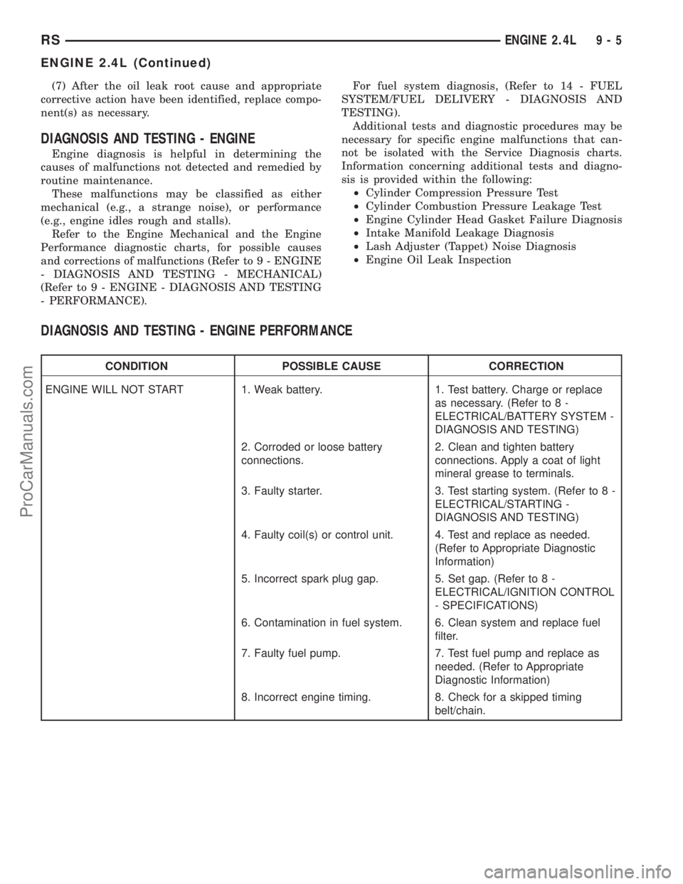
DIAGNOSIS AND TESTING - ENGINE
Engine diagnosis is helpful in determining the
causes of malfunctions not detected and remedied by
routine maintenance.
These malfunctions may be classified as either
mechanical (e.g., a strange noise), or performance
(e.g., engine idles rough and stalls).
Refer to the Engine Mechanical and the Engine
Performance diagnostic charts, for possible causes
and corrections of malfunctions (Refer to 9 - ENGINE
- DIAGNOSIS AND TESTING - MECHANICAL)
(Refer to 9 - ENGINE - DIAGNOSIS AND TESTING
- PERFORMANCE).For fuel system diagnosis, (Refer to 14 - FUEL
SYSTEM/FUEL DELIVERY - DIAGNOSIS AND
TESTING).
Additional tests and diagnostic procedures may be
necessary for specific engine malfunctions that can-
not be isolated with the Service Diagnosis charts.
Information concerning additional tests and diagno-
sis is provided within the following:
²Cylinder Compression Pressure Test
²Cylinder Combustion Pressure Leakage Test
²Engine Cylinder Head Gasket Failure Diagnosis
²Intake Manifold Leakage Diagnosis
²Lash Adjuster (Tappet) Noise Diagnosis
²Engine Oil Leak Inspection
DIAGNOSIS AND TESTING - ENGINE PERFORMANCE
CONDITION POSSIBLE CAUSE CORRECTION
ENGINE WILL NOT START 1. Weak battery. 1. Test battery. Charge or replace
as necessary. (Refer to 8 -
ELECTRICAL/BATTERY SYSTEM -
DIAGNOSIS AND TESTING)
2. Corroded or loose battery
connections.2. Clean and tighten battery
connections. Apply a coat of light
mineral grease to terminals.
3. Faulty starter. 3. Test starting system. (Refer to 8 -
ELECTRICAL/STARTING -
DIAGNOSIS AND TESTING)
4. Faulty coil(s) or control unit. 4. Test and replace as needed.
(Refer to Appropriate Diagnostic
Information)
5. Incorrect spark plug gap. 5. Set gap. (Refer to 8 -
ELECTRICAL/IGNITION CONTROL
- SPECIFICATIONS)
6. Contamination in fuel system. 6. Clean system and replace fuel
filter.
7. Faulty fuel pump. 7. Test fuel pump and replace as
needed. (Refer to Appropriate
Diagnostic Information)
8. Incorrect engine timing. 8. Check for a skipped timing
belt/chain.
RSENGINE 2.4L9-5
ENGINE 2.4L (Continued)
ProCarManuals.com
Page 1163 of 2321
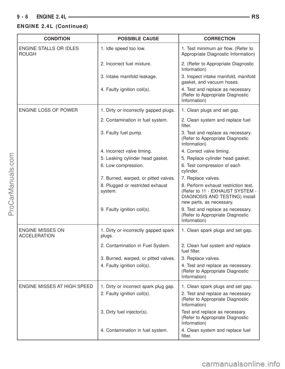
CONDITION POSSIBLE CAUSE CORRECTION
ENGINE STALLS OR IDLES
ROUGH1. Idle speed too low. 1. Test minimum air flow. (Refer to
Appropriate Diagnostic Information)
2. Incorrect fuel mixture. 2. (Refer to Appropriate Diagnostic
Information)
3. Intake manifold leakage. 3. Inspect intake manifold, manifold
gasket, and vacuum hoses.
4. Faulty ignition coil(s). 4. Test and replace as necessary.
(Refer to Appropriate Diagnostic
Information)
ENGINE LOSS OF POWER 1. Dirty or incorrectly gapped plugs. 1. Clean plugs and set gap.
2. Contamination in fuel system. 2. Clean system and replace fuel
filter.
3. Faulty fuel pump. 3. Test and replace as necessary.
(Refer to Appropriate Diagnostic
Information)
4. Incorrect valve timing. 4. Correct valve timing.
5. Leaking cylinder head gasket. 5. Replace cylinder head gasket.
6. Low compression. 6. Test compression of each
cylinder.
7. Burned, warped, or pitted valves. 7. Replace valves.
8. Plugged or restricted exhaust
system.8. Perform exhaust restriction test.
(Refer to 11 - EXHAUST SYSTEM -
DIAGNOSIS AND TESTING) Install
new parts, as necessary.
9. Faulty ignition coil(s). 9. Test and replace as necessary.
(Refer to Appropriate Diagnostic
Information)
ENGINE MISSES ON
ACCELERATION1. Dirty or incorrectly gapped spark
plugs.1. Clean spark plugs and set gap.
2. Contamination in Fuel System. 2. Clean fuel system and replace
fuel filter.
3. Burned, warped, or pitted valves. 3. Replace valves.
4. Faulty ignition coil(s). 4. Test and replace as necessary.
(Refer to Appropriate Diagnostic
Information)
ENGINE MISSES AT HIGH SPEED 1. Dirty or incorrect spark plug gap. 1. Clean spark plugs and set gap.
2. Faulty ignition coil(s). 2. Test and replace as necessary.
(Refer to Appropriate Diagnostic
Information)
3. Dirty fuel injector(s). Test and replace as necessary.
(Refer to Appropriate Diagnostic
Information)
4. Contamination in fuel system. 4. Clean system and replace fuel
filter.
9 - 6 ENGINE 2.4LRS
ENGINE 2.4L (Continued)
ProCarManuals.com