2001 DODGE TOWN AND COUNTRY sensor
[x] Cancel search: sensorPage 1208 of 2321
(3) Start engine and record oil pressure. Refer to
Specifications for correct oil pressure requirements.
(Refer to 9 - ENGINE - SPECIFICATIONS)
CAUTION: If oil pressure is 0 at idle, do not perform
the 3000 RPM test
(4) If oil pressure is 0 at idle. Shut off engine,
check for pressure relief valve stuck open, a clogged
oil pick-up screen or a damaged oil pick-up tube
O-ring.
(5) After test is complete, remove test gauge and
fitting.
(6) Install oil pressure switch and connector. (Refer
to 9 - ENGINE/LUBRICATION/OIL PRESSURE
SENSOR/SWITCH - INSTALLATION)
OIL
ENGINE OIL LEVEL CHECK
The best time to check engine oil level is after it
has sat overnight, or if the engine has been running,
allow the engine to be shut off for at least 5 minutes
before checking oil level.
Checking the oil while the vehicle is on level
ground will improve the accuracy of the oil level
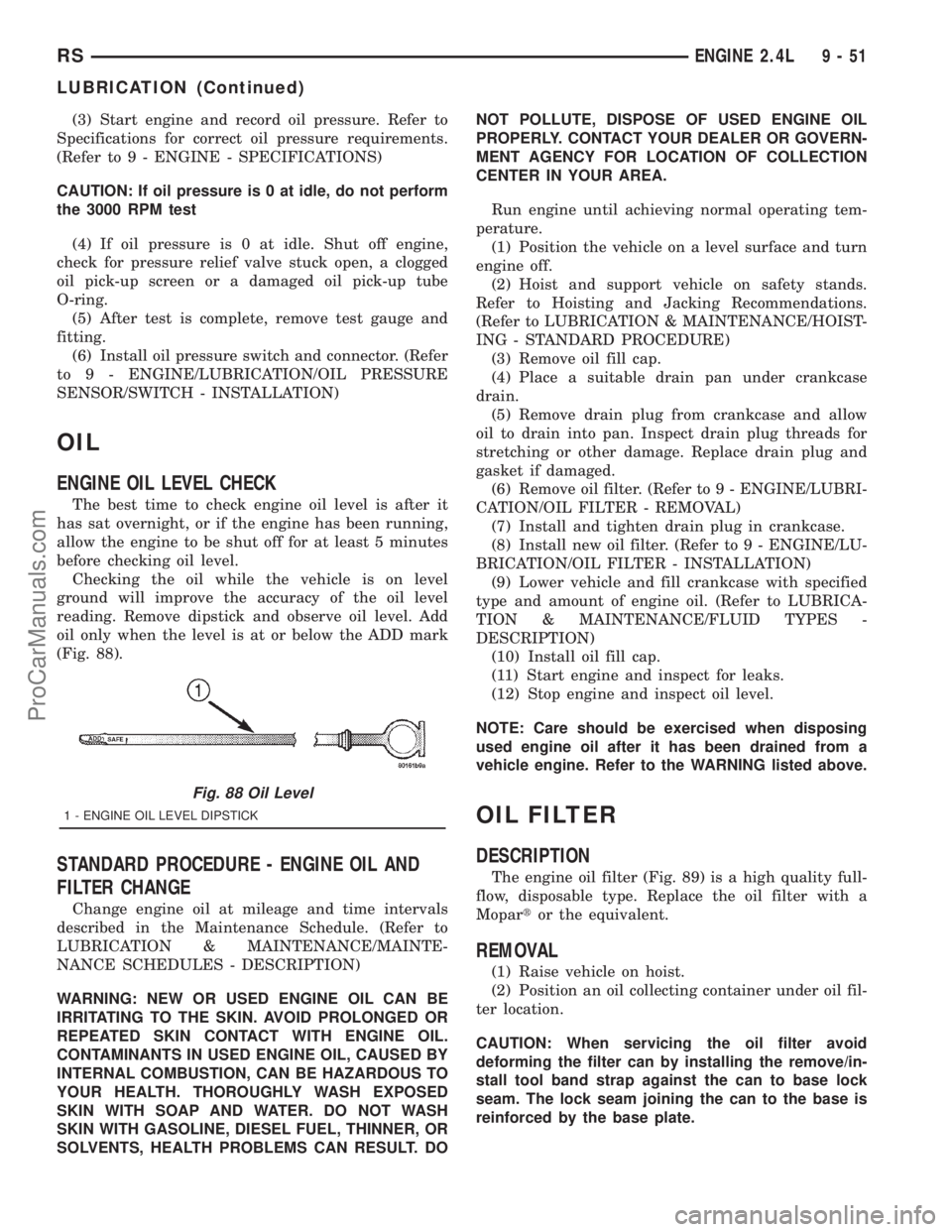
reading. Remove dipstick and observe oil level. Add
oil only when the level is at or below the ADD mark
(Fig. 88).
STANDARD PROCEDURE - ENGINE OIL AND
FILTER CHANGE
Change engine oil at mileage and time intervals
described in the Maintenance Schedule. (Refer to
LUBRICATION & MAINTENANCE/MAINTE-
NANCE SCHEDULES - DESCRIPTION)
WARNING: NEW OR USED ENGINE OIL CAN BE
IRRITATING TO THE SKIN. AVOID PROLONGED OR
REPEATED SKIN CONTACT WITH ENGINE OIL.
CONTAMINANTS IN USED ENGINE OIL, CAUSED BY
INTERNAL COMBUSTION, CAN BE HAZARDOUS TO
YOUR HEALTH. THOROUGHLY WASH EXPOSED
SKIN WITH SOAP AND WATER. DO NOT WASH
SKIN WITH GASOLINE, DIESEL FUEL, THINNER, OR
SOLVENTS, HEALTH PROBLEMS CAN RESULT. DONOT POLLUTE, DISPOSE OF USED ENGINE OIL
PROPERLY. CONTACT YOUR DEALER OR GOVERN-
MENT AGENCY FOR LOCATION OF COLLECTION
CENTER IN YOUR AREA.
Run engine until achieving normal operating tem-
perature.
(1) Position the vehicle on a level surface and turn
engine off.
(2) Hoist and support vehicle on safety stands.
Refer to Hoisting and Jacking Recommendations.
(Refer to LUBRICATION & MAINTENANCE/HOIST-
ING - STANDARD PROCEDURE)
(3) Remove oil fill cap.
(4) Place a suitable drain pan under crankcase
drain.
(5) Remove drain plug from crankcase and allow
oil to drain into pan. Inspect drain plug threads for
stretching or other damage. Replace drain plug and
gasket if damaged.
(6) Remove oil filter. (Refer to 9 - ENGINE/LUBRI-
CATION/OIL FILTER - REMOVAL)
(7) Install and tighten drain plug in crankcase.
(8) Install new oil filter. (Refer to 9 - ENGINE/LU-
BRICATION/OIL FILTER - INSTALLATION)
(9) Lower vehicle and fill crankcase with specified
type and amount of engine oil. (Refer to LUBRICA-
TION & MAINTENANCE/FLUID TYPES -
DESCRIPTION)
(10) Install oil fill cap.
(11) Start engine and inspect for leaks.
(12) Stop engine and inspect oil level.
NOTE: Care should be exercised when disposing
used engine oil after it has been drained from a
vehicle engine. Refer to the WARNING listed above.
OIL FILTER
DESCRIPTION
The engine oil filter (Fig. 89) is a high quality full-
flow, disposable type. Replace the oil filter with a
Mopartor the equivalent.
REMOVAL
(1) Raise vehicle on hoist.
(2) Position an oil collecting container under oil fil-
ter location.
CAUTION: When servicing the oil filter avoid
deforming the filter can by installing the remove/in-
stall tool band strap against the can to base lock
seam. The lock seam joining the can to the base is
reinforced by the base plate.
Fig. 88 Oil Level
1 - ENGINE OIL LEVEL DIPSTICK
RSENGINE 2.4L9-51
LUBRICATION (Continued)
ProCarManuals.com
Page 1213 of 2321
INTAKE MANIFOLD
DESCRIPTION
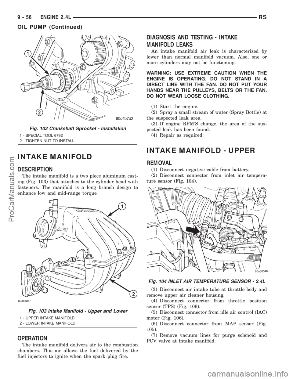
The intake manifold is a two piece aluminum cast-
ing (Fig. 103) that attaches to the cylinder head with
fasteners. The manifold is a long branch design to
enhance low and mid-range torque
OPERATION
The intake manifold delivers air to the combustion
chambers. This air allows the fuel delivered by the
fuel injectors to ignite when the spark plug fire.
DIAGNOSIS AND TESTING - INTAKE
MANIFOLD LEAKS
An intake manifold air leak is characterized by
lower than normal manifold vacuum. Also, one or
more cylinders may not be functioning.
WARNING: USE EXTREME CAUTION WHEN THE
ENGINE IS OPERATING. DO NOT STAND IN A
DIRECT LINE WITH THE FAN. DO NOT PUT YOUR
HANDS NEAR THE PULLEYS, BELTS OR THE FAN.
DO NOT WEAR LOOSE CLOTHING.
(1) Start the engine.
(2) Spray a small stream of water (Spray Bottle) at
the suspected leak area.
(3) If engine RPM'S change, the area of the sus-
pected leak has been found.
(4) Repair as required.
INTAKE MANIFOLD - UPPER
REMOVAL
(1) Disconnect negative cable from battery.
(2) Disconnect connector from inlet air tempera-
ture sensor (Fig. 104).
(3) Disconnect air intake tube at throttle body and
remove upper air cleaner housing.
(4) Disconnect connector from throttle position
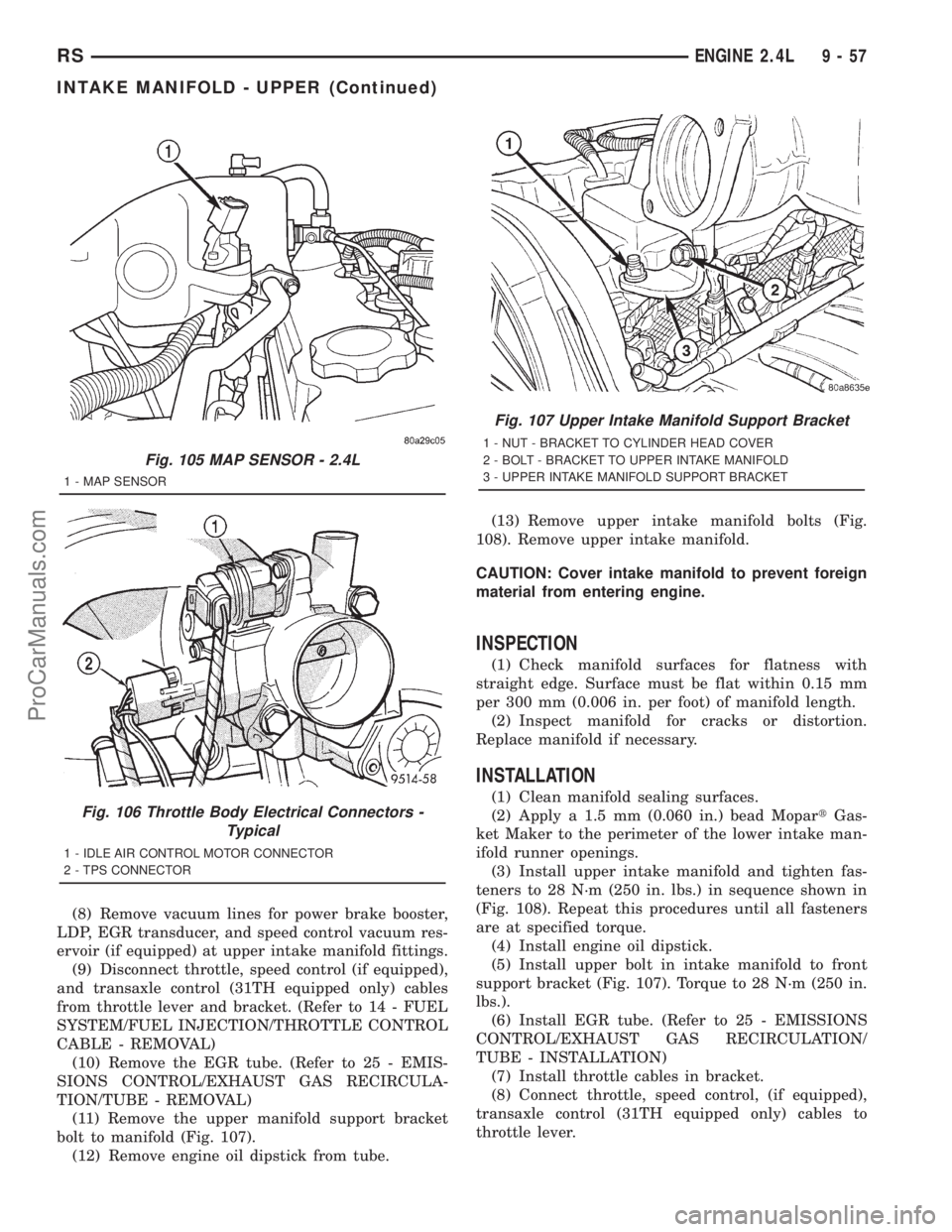
sensor (TPS) (Fig. 106).
(5) Disconnect connector from idle air control (IAC)
motor (Fig. 106).
(6) Disconnect connector from MAP sensor (Fig.
105).
(7) Remove vacuum lines for purge solenoid and
PCV valve at intake manifold.
Fig. 102 Crankshaft Sprocket - Installation
1 - SPECIAL TOOL 6792
2 - TIGHTEN NUT TO INSTALL
Fig. 103 Intake Manifold - Upper and Lower
1 - UPPER INTAKE MANIFOLD
2 - LOWER INTAKE MANIFOLD
Fig. 104 INLET AIR TEMPERATURE SENSOR - 2.4L
9 - 56 ENGINE 2.4LRS
OIL PUMP (Continued)
ProCarManuals.com
Page 1214 of 2321
(8) Remove vacuum lines for power brake booster,
LDP, EGR transducer, and speed control vacuum res-
ervoir (if equipped) at upper intake manifold fittings.
(9) Disconnect throttle, speed control (if equipped),
and transaxle control (31TH equipped only) cables
from throttle lever and bracket. (Refer to 14 - FUEL
SYSTEM/FUEL INJECTION/THROTTLE CONTROL
CABLE - REMOVAL)
(10) Remove the EGR tube. (Refer to 25 - EMIS-
SIONS CONTROL/EXHAUST GAS RECIRCULA-
TION/TUBE - REMOVAL)
(11) Remove the upper manifold support bracket
bolt to manifold (Fig. 107).
(12) Remove engine oil dipstick from tube.(13) Remove upper intake manifold bolts (Fig.
108). Remove upper intake manifold.
CAUTION: Cover intake manifold to prevent foreign
material from entering engine.
INSPECTION
(1) Check manifold surfaces for flatness with
straight edge. Surface must be flat within 0.15 mm
per 300 mm (0.006 in. per foot) of manifold length.
(2) Inspect manifold for cracks or distortion.
Replace manifold if necessary.
INSTALLATION
(1) Clean manifold sealing surfaces.
(2) Apply a 1.5 mm (0.060 in.) bead MopartGas-
ket Maker to the perimeter of the lower intake man-
ifold runner openings.
(3) Install upper intake manifold and tighten fas-
teners to 28 N´m (250 in. lbs.) in sequence shown in
(Fig. 108). Repeat this procedures until all fasteners
are at specified torque.
(4) Install engine oil dipstick.
(5) Install upper bolt in intake manifold to front
support bracket (Fig. 107). Torque to 28 N´m (250 in.
lbs.).
(6) Install EGR tube. (Refer to 25 - EMISSIONS
CONTROL/EXHAUST GAS RECIRCULATION/
TUBE - INSTALLATION)
(7) Install throttle cables in bracket.
(8) Connect throttle, speed control, (if equipped),
transaxle control (31TH equipped only) cables to
throttle lever.
Fig. 105 MAP SENSOR - 2.4L
1 - MAP SENSOR
Fig. 106 Throttle Body Electrical Connectors -
Typical
1 - IDLE AIR CONTROL MOTOR CONNECTOR
2 - TPS CONNECTOR
Fig. 107 Upper Intake Manifold Support Bracket
1 - NUT - BRACKET TO CYLINDER HEAD COVER
2 - BOLT - BRACKET TO UPPER INTAKE MANIFOLD
3 - UPPER INTAKE MANIFOLD SUPPORT BRACKET
RSENGINE 2.4L9-57
INTAKE MANIFOLD - UPPER (Continued)
ProCarManuals.com
Page 1215 of 2321
(9) Connect vacuum lines for power brake booster,
LDP, EGR transducer, and speed control vacuum res-
ervoir (if equipped) at upper intake manifold fittings.
(10) Connect vacuum lines for purge solenoid and
PCV valve.
(11) Connect electrical connectors for MAP sensor,
throttle position sensor (TPS), and idle air control
(IAC) motor.
(12) Install air cleaner upper housing and air
intake tube to throttle body.
(13) Connect inlet air temperature sensor connec-
tor (Fig. 104).
(14) Connect negative cable to battery.
INTAKE MANIFOLD - LOWER
REMOVAL
(1) Perform fuel system pressure release proce-
durebefore attempting any repairs.(Refer to 14 -
FUEL SYSTEM/FUEL DELIVERY - STANDARD
PROCEDURE)
(2) Remove upper intake manifold. (Refer to 9 -
ENGINE/MANIFOLDS/INTAKE MANIFOLD -
REMOVAL)
CAUTION: Cover intake manifold openings to pre-
vent foreign material from entering engine.
(3) Disconnect fuel line. (Refer to 14 - FUEL SYS-
TEM/FUEL DELIVERY/QUICK CONNECT FIT-
TING - STANDARD PROCEDURE)
(4) Drain the cooling system. (Refer to 7 - COOL-
ING - STANDARD PROCEDURE)
(5) Remove heater supply and radiator upper
hoses at intake manifold.
(6) Disconnect coolant temperature sensor/fuel
injector wire harness connector.
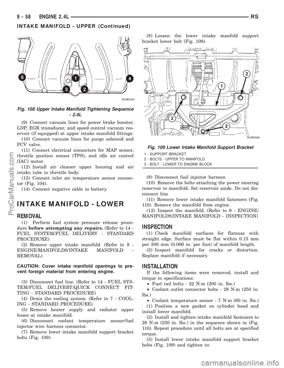
(7) Remove lower intake manifold support bracket
bolts (Fig. 109).(8) Loosen the lower intake manfold support
bracket lower bolt (Fig. 109).
(9) Disconnect fuel injector harness.
(10) Remove the bolts attaching the power steering
reservoir to manifold. Set reservoir aside. Do not dis-
connect line
(11) Remove lower intake manifold fasteners (Fig.
110). Remove the manifold from engine.
(12) Inspect the manifold. (Refer to 9 - ENGINE/
MANIFOLDS/INTAKE MANIFOLD - INSPECTION)
INSPECTION
(1) Check manifold surfaces for flatness with
straight edge. Surface must be flat within 0.15 mm
per 300 mm (0.006 in. per foot) of manifold length.
(2) Inspect manifold for cracks or distortion.
Replace manifold if necessary.
INSTALLATION
If the following items were removed, install and
torque to specifications:
²Fuel rail bolts - 22 N´m (200 in. lbs.)
²Coolant outlet connector bolts - 28 N´m (250 in.
lbs.)
²Coolant temperature sensor - 7 N´m (60 in. lbs.)
(1) Position a new gasket on cylinder head and
install lower manifold.
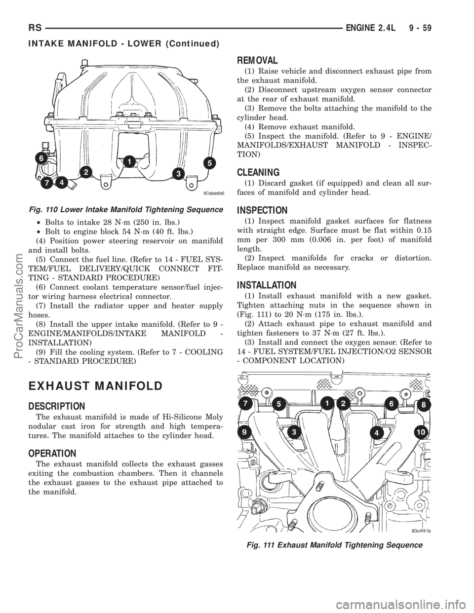
(2) Install and tighten intake manifold fasteners to
28 N´m (250 in. lbs.) in the sequence shown in (Fig.
110). Repeat procedure until all bolts are at specified
torque.
(3) Install lower intake manifold support bracket
bolts (Fig. 109) and tighten to:
Fig. 108 Upper Intake Manifold Tightening Sequence
- 2.4L
Fig. 109 Lower Intake Manifold Support Bracket
1 - SUPPORT BRACKET
2 - BOLTS - UPPER TO MANIFOLD
3 - BOLT - LOWER TO ENGINE BLOCK
9 - 58 ENGINE 2.4LRS
INTAKE MANIFOLD - UPPER (Continued)
ProCarManuals.com
Page 1216 of 2321
²Bolts to intake 28 N´m (250 in. lbs.)
²Bolt to engine block 54 N´m (40 ft. lbs.)
(4) Position power steering reservoir on manifold
and install bolts.
(5) Connect the fuel line. (Refer to 14 - FUEL SYS-
TEM/FUEL DELIVERY/QUICK CONNECT FIT-
TING - STANDARD PROCEDURE)
(6) Connect coolant temperature sensor/fuel injec-
tor wiring harness electrical connector.
(7) Install the radiator upper and heater supply
hoses.
(8) Install the upper intake manifold. (Refer to 9 -
ENGINE/MANIFOLDS/INTAKE MANIFOLD -
INSTALLATION)
(9) Fill the cooling system. (Refer to 7 - COOLING
- STANDARD PROCEDURE)
EXHAUST MANIFOLD
DESCRIPTION
The exhaust manifold is made of Hi-Silicone Moly
nodular cast iron for strength and high tempera-
tures. The manifold attaches to the cylinder head.
OPERATION
The exhaust manifold collects the exhaust gasses
exiting the combustion chambers. Then it channels
the exhaust gasses to the exhaust pipe attached to
the manifold.
REMOVAL
(1) Raise vehicle and disconnect exhaust pipe from
the exhaust manifold.
(2) Disconnect upstream oxygen sensor connector
at the rear of exhaust manifold.
(3) Remove the bolts attaching the manifold to the
cylinder head.
(4) Remove exhaust manifold.
(5) Inspect the manifold. (Refer to 9 - ENGINE/
MANIFOLDS/EXHAUST MANIFOLD - INSPEC-
TION)
CLEANING
(1) Discard gasket (if equipped) and clean all sur-
faces of manifold and cylinder head.
INSPECTION
(1) Inspect manifold gasket surfaces for flatness
with straight edge. Surface must be flat within 0.15
mm per 300 mm (0.006 in. per foot) of manifold
length.
(2) Inspect manifolds for cracks or distortion.
Replace manifold as necessary.
INSTALLATION
(1) Install exhaust manifold with a new gasket.
Tighten attaching nuts in the sequence shown in
(Fig. 111) to 20 N´m (175 in. lbs.).
(2) Attach exhaust pipe to exhaust manifold and
tighten fasteners to 37 N´m (27 ft. lbs.).
(3) Install and connect the oxygen sensor. (Refer to
14 - FUEL SYSTEM/FUEL INJECTION/O2 SENSOR
- COMPONENT LOCATION)
Fig. 110 Lower Intake Manifold Tightening Sequence
Fig. 111 Exhaust Manifold Tightening Sequence
RSENGINE 2.4L9-59
INTAKE MANIFOLD - LOWER (Continued)
ProCarManuals.com
Page 1229 of 2321
REMOVAL.............................114
INSTALLATION..........................115
CRANKSHAFT OIL SEAL - FRONT
REMOVAL.............................115
INSTALLATION..........................115
CRANKSHAFT OIL SEAL - REAR
REMOVAL.............................116
INSTALLATION..........................117
CRANKSHAFT REAR OIL SEAL RETAINER
REMOVAL.............................117
INSTALLATION..........................117
FLEX PLATE
REMOVAL.............................118
INSTALLATION..........................118
HYDRAULIC LIFTERS (CAM IN BLOCK)
DESCRIPTION..........................118
DIAGNOSIS AND TESTING................118
HYDRAULIC LIFTERS...................118
REMOVAL.............................119
INSTALLATION..........................119
PISTON & CONNECTING ROD
DESCRIPTION..........................119
OPERATION............................120
STANDARD PROCEDURE.................120
CONNECTING ROD AND BEARING -
FITTING.............................120
PISTON - FITTING.....................121
REMOVAL.............................121
INSTALLATION..........................122
PISTON RINGS
STANDARD PROCEDURE.................124
PISTON RING - FITTING................124
REMOVAL.............................124
INSTALLATION..........................125
VIBRATION DAMPER
REMOVAL.............................126
INSTALLATION..........................126
ENGINE MOUNTING
DESCRIPTION..........................127
FRONT MOUNT
REMOVAL.............................127
INSTALLATION..........................127
LEFT MOUNT
REMOVAL.............................128
INSTALLATION..........................128
REAR MOUNT
REMOVAL.............................129
INSTALLATION..........................130
RIGHT MOUNT
REMOVAL.............................130
INSTALLATION..........................131
LUBRICATION
DESCRIPTION..........................131
OPERATION............................131
DIAGNOSIS AND TESTING................131
ENGINE OIL PRESSURE................131OIL
STANDARD PROCEDURE.................132
ENGINE OIL CHANGE..................132
ENGINE OIL LEVEL CHECK..............133
OIL COOLER & LINES
DESCRIPTION..........................134
OPERATION............................134
REMOVAL.............................134
INSTALLATION..........................134
OIL FILTER
REMOVAL.............................135
INSTALLATION..........................135
OIL FILTER ADAPTER
REMOVAL.............................135
INSTALLATION..........................135
OIL PAN
REMOVAL.............................136
CLEANING.............................136
INSPECTION...........................136
INSTALLATION..........................136
OIL PRESSURE RELIEF VALVE
REMOVAL.............................137
INSTALLATION..........................137
OIL PRESSURE SENSOR/SWITCH
DESCRIPTION..........................137
OPERATION............................138
REMOVAL.............................138
INSTALLATION..........................138
OIL PUMP
DESCRIPTION..........................138
REMOVAL.............................138
DISASSEMBLY..........................138
CLEANING.............................138
INSPECTION...........................138
ASSEMBLY............................140
INSTALLATION..........................140
INTAKE MANIFOLD
DESCRIPTION..........................140
OPERATION............................141
DIAGNOSIS AND TESTING................141
INTAKE MANIFOLD LEAKS..............141
INTAKE MANIFOLD - UPPER 3.3L
STANDARD PROCEDURE.................141
MANIFOLD STRIPPED THREAD REPAIR....141
INTAKE MANIFOLD VACUUM PORT REPAIR . 142
REMOVAL.............................143
CLEANING.............................144
INSPECTION...........................144
INSTALLATION..........................144
INTAKE MANIFOLD - UPPER 3.8L
REMOVAL.............................145
CLEANING.............................146
INSPECTION...........................147
INSTALLATION..........................147
INTAKE MANIFOLD - LOWER
REMOVAL.............................148
CLEANING.............................148
9 - 72 ENGINE 3.3/3.8LRS
ProCarManuals.com
Page 1239 of 2321
REMOVAL - ENGINE ASSEMBLY
(1) Perform fuel pressure release procedure. (Refer
to 14 - FUEL SYSTEM/FUEL DELIVERY - STAN-
DARD PROCEDURE)
(2) Disconnect the battery.
(3) Remove air cleaner and hoses.
(4) Disconnect the fuel line from fuel rail. (Refer to
14 - FUEL SYSTEM/FUEL DELIVERY/QUICK
CONNECT FITTING - STANDARD PROCEDURE)
(5) Remove the wiper module. (Refer to 8 - ELEC-
TRICAL/WIPERS/WASHERS/WIPER MODULE -
REMOVAL)
(6) Block off heater hoses to the rear heater sys-
tem, if equipped, using pinch-off pliers.
(7) Drain the cooling system. (Refer to 7 - COOL-
ING - STANDARD PROCEDURE)
(8) Disconnect the heater hoses.
(9) Remove the radiator upper support crossmem-
ber. (Refer to 23 - BODY/EXTERIOR/GRILLE OPEN-
ING REINFORCEMENT - REMOVAL)
(10) Remove the radiator fans. (Refer to 7 - COOL-
ING/ENGINE/RADIATOR FAN - REMOVAL)
(11) Disconnect the throttle cables from the throt-
tle body.
(12) Disconnect the MAP, IAC, and TPS electrical
connectors.
(13) Disconnect the EGR transducer electrical con-
nector.
(14) Disconnect the vacuum hoses from throttle
body.
(15) Disconnect the brake booster and speed con-
trol vacuum hoses.(16) Disengage wire harness clip from the right
side engine mount.
(17) Remove the power steering reservoir from
mounting position and set aside. Do not disconnect
hose.
(18) Disconnect ground strap from rear of cylinder
head.
(19) Disconnect engine coolant temperature (ECT)
sensor and ignition coil electrical connectors.
(20) Disconnect the fuel injector electrical harness
connector and disengage clip from support bracket.
(21) Disconnect crank sensor connector.
(22) Disconnect camshaft sensor connector.
(23) Evacuate air conditioning system.
(24) Disconnect A/C compressor electrical connec-
tor.
(25) Disconnect the A/C lines from compressor.
Cover and seal all openings of hoses and compressor.
(26) Remove the radiator upper hose.
(27) Disengage electrical harness clip at transaxle
dipstick tube.
(28) Remove transaxle dipstick tube. Seal opening
using a suitable plug.
(29) Disconnect cooler hoses from transaxle.
(30) Disconnect transaxle shift linkage and electri-
cal connectors.
(31) Raise vehicle on hoist and drain the engine
oil.
(32) Remove the axle shafts. (Refer to 3 - DIFFER-
ENTIAL & DRIVELINE/HALF SHAFT - REMOVAL)
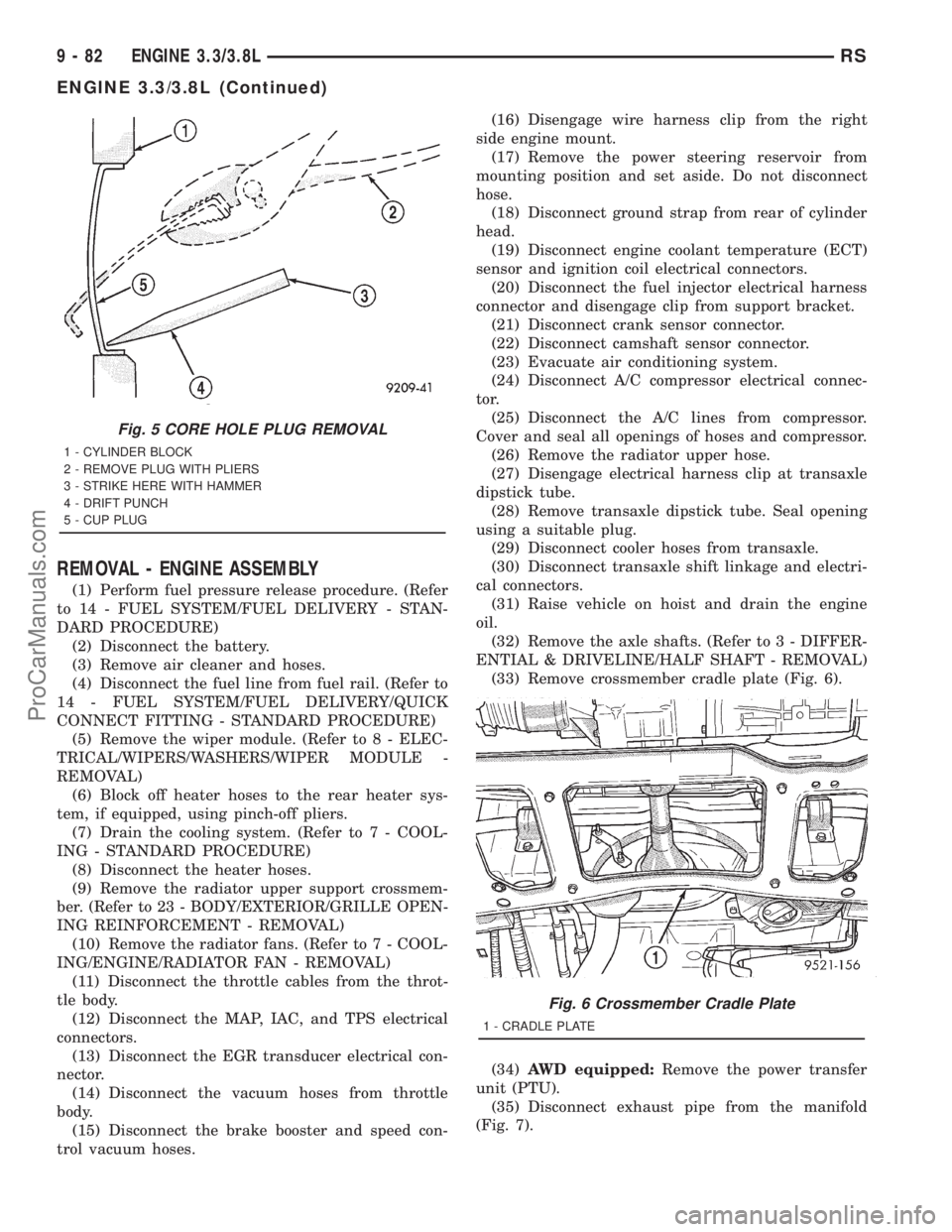
(33) Remove crossmember cradle plate (Fig. 6).
(34)AWD equipped:Remove the power transfer
unit (PTU).
(35) Disconnect exhaust pipe from the manifold
(Fig. 7).
Fig. 5 CORE HOLE PLUG REMOVAL
1 - CYLINDER BLOCK
2 - REMOVE PLUG WITH PLIERS
3 - STRIKE HERE WITH HAMMER
4 - DRIFT PUNCH
5 - CUP PLUG
Fig. 6 Crossmember Cradle Plate
1 - CRADLE PLATE
9 - 82 ENGINE 3.3/3.8LRS
ENGINE 3.3/3.8L (Continued)
ProCarManuals.com
Page 1240 of 2321
(36) Remove front engine mount and bracket as an
assembly.
(37) Remove the engine rear mount bracket.
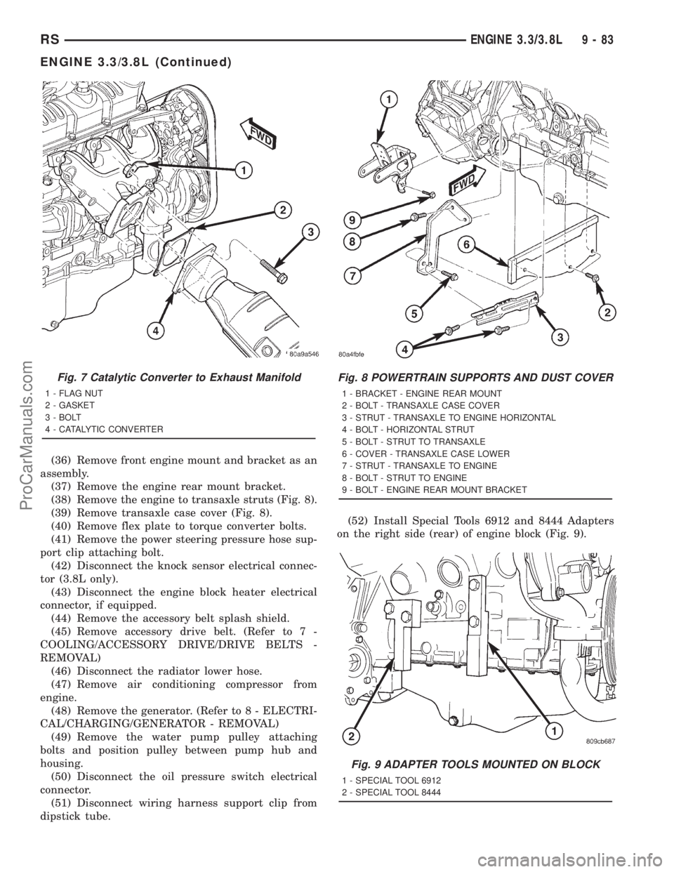
(38) Remove the engine to transaxle struts (Fig. 8).
(39) Remove transaxle case cover (Fig. 8).
(40) Remove flex plate to torque converter bolts.
(41) Remove the power steering pressure hose sup-
port clip attaching bolt.
(42) Disconnect the knock sensor electrical connec-
tor (3.8L only).
(43) Disconnect the engine block heater electrical
connector, if equipped.
(44) Remove the accessory belt splash shield.
(45) Remove accessory drive belt. (Refer to 7 -
COOLING/ACCESSORY DRIVE/DRIVE BELTS -
REMOVAL)
(46) Disconnect the radiator lower hose.
(47) Remove air conditioning compressor from
engine.
(48) Remove the generator. (Refer to 8 - ELECTRI-
CAL/CHARGING/GENERATOR - REMOVAL)
(49) Remove the water pump pulley attaching
bolts and position pulley between pump hub and
housing.
(50) Disconnect the oil pressure switch electrical
connector.
(51) Disconnect wiring harness support clip from
dipstick tube.(52) Install Special Tools 6912 and 8444 Adapters
on the right side (rear) of engine block (Fig. 9).
Fig. 7 Catalytic Converter to Exhaust Manifold
1 - FLAG NUT
2 - GASKET
3 - BOLT
4 - CATALYTIC CONVERTER
Fig. 8 POWERTRAIN SUPPORTS AND DUST COVER
1 - BRACKET - ENGINE REAR MOUNT
2 - BOLT - TRANSAXLE CASE COVER
3 - STRUT - TRANSAXLE TO ENGINE HORIZONTAL
4 - BOLT - HORIZONTAL STRUT
5 - BOLT - STRUT TO TRANSAXLE
6 - COVER - TRANSAXLE CASE LOWER
7 - STRUT - TRANSAXLE TO ENGINE
8 - BOLT - STRUT TO ENGINE
9 - BOLT - ENGINE REAR MOUNT BRACKET
Fig. 9 ADAPTER TOOLS MOUNTED ON BLOCK
1 - SPECIAL TOOL 6912
2 - SPECIAL TOOL 8444
RSENGINE 3.3/3.8L9-83
ENGINE 3.3/3.8L (Continued)
ProCarManuals.com