2001 DODGE TOWN AND COUNTRY light
[x] Cancel search: lightPage 1622 of 2321
TORQUE CONVERTER CLUTCH (TCC)
In a standard torque converter, the impeller and
turbine are rotating at about the same speed and the
stator is freewheeling, providing no torque multipli-
cation. By applying the turbine's piston to the front
cover's friction material, a total converter engage-
ment can be obtained. The result of this engagement
is a direct 1:1 mechanical link between the engine
and the transmission.
The engagement and disengagement of the TCC
are automatic and controlled by the Powertrain Con-
trol Module (PCM). The engagement cannot be acti-
vated in the lower gears because it eliminates the
torque multiplication effect of the torque converter
necessary for acceleration. Inputs that determine
clutch engagement are: coolant temperature, vehicle
speed and throttle position. The torque converter
clutch is engaged by the clutch solenoid on the valve
body. The clutch will engage at approximately 56
km/h (35 mph) with light throttle, after the shift to
third gear.
REMOVAL
(1) Remove transmission and torque converter
from vehicle. (Refer to 21 - TRANSMISSION/TRANS-
AXLE/AUTOMATIC - 31TH - REMOVAL)
(2) Place a suitable drain pan under the converter
housing end of the transmission.
CAUTION: Verify that transmission is secure on the
lifting device or work surface, the center of gravity
of the transmission will shift when the torque con-
verter is removed creating an unstable condition.
The torque converter is a heavy unit. Use caution
when separating the torque converter from the
transmission.
(3) Pull the torque converter forward until the cen-
ter hub clears the oil pump seal.
(4) Separate the torque converter from the trans-
mission.
INSTALLATION
Check converter hub and drive notches for sharp
edges, burrs, scratches, or nicks. Polish the hub and
notches with 320/400 grit paper or crocus cloth if nec-
essary. The hub must be smooth to avoid damaging
the pump seal at installation.(1) Lubricate converter hub and oil pump seal lip
with transmission fluid.
(2) Place torque converter in position on transmis-
sion.
CAUTION: Do not damage oil pump seal or bushing
while inserting torque converter into the front of the
transmission.
(3) Align torque converter to oil pump seal open-
ing.
(4) Insert torque converter hub into oil pump.
(5) While pushing torque converter inward, rotate
converter until converter is fully seated in the oil
pump gears.
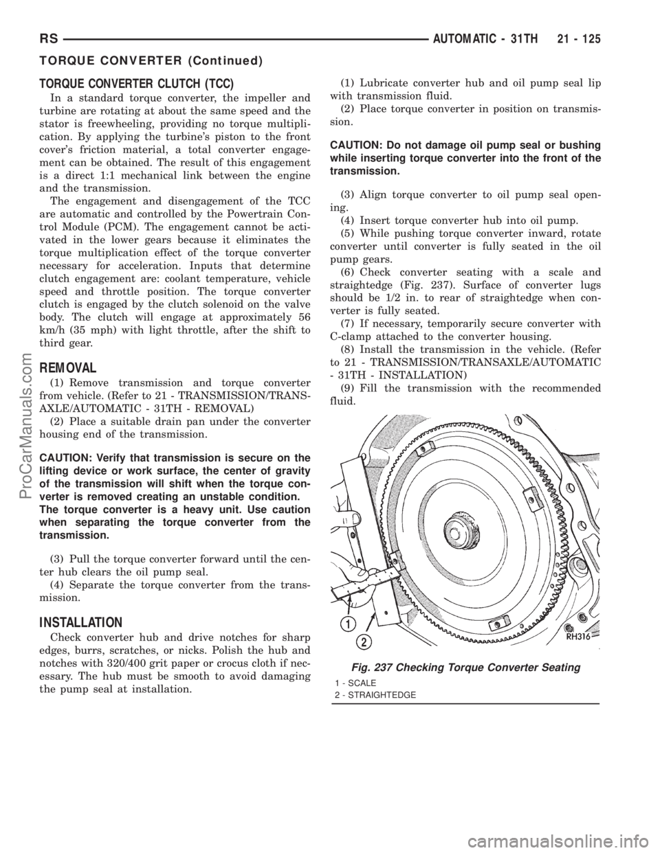
(6) Check converter seating with a scale and
straightedge (Fig. 237). Surface of converter lugs
should be 1/2 in. to rear of straightedge when con-
verter is fully seated.
(7) If necessary, temporarily secure converter with
C-clamp attached to the converter housing.
(8) Install the transmission in the vehicle. (Refer
to 21 - TRANSMISSION/TRANSAXLE/AUTOMATIC
- 31TH - INSTALLATION)
(9) Fill the transmission with the recommended
fluid.
Fig. 237 Checking Torque Converter Seating
1 - SCALE
2 - STRAIGHTEDGE
RSAUTOMATIC - 31TH21 - 125
TORQUE CONVERTER (Continued)
ProCarManuals.com
Page 1642 of 2321
DISASSEMBLY
CAUTION: Do not clamp any portion of valve body
or transfer plate in a vise. Any slight distortion of
the aluminum body or transfer plate will result in
sticking valves, excessive leakage, or both. When
removing or installing valves or plugs, slide them in
or out carefully. Do not use force.
NOTE: TAG ALL SPRINGS AS THEY ARE REMOVED
FOR REASSEMBLY IDENTIFICATION.
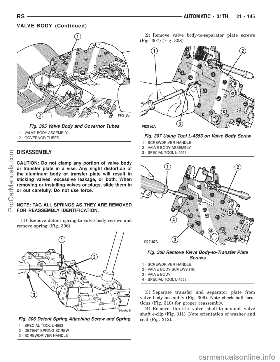
(1) Remove detent spring-to-valve body screws and
remove spring (Fig. 306).(2) Remove valve body-to-separator plate screws
(Fig. 307) (Fig. 308).
(3) Separate transfer and separator plate from
valve body assembly (Fig. 309). Note check ball loca-
tions (Fig. 310) for proper reassembly.
(4) Remove throttle valve shaft-to-manual valve
shaft e-clip (Fig. 311). Note orientation of washer and
seal (Fig. 312).
Fig. 305 Valve Body and Governor Tubes
1 - VALVE BODY ASSEMBLY
2 - GOVERNOR TUBES
Fig. 306 Detent Spring Attaching Screw and Spring
1 - SPECIAL TOOL L-4553
2 - DETENT SPRING SCREW
3 - SCREWDRIVER HANDLE
Fig. 307 Using Tool L-4553 on Valve Body Screw
1 - SCREWDRIVER HANDLE
2 - VALVE BODY ASSEMBLY
3 - SPECIAL TOOL L-4553
Fig. 308 Remove Valve Body-to-Transfer Plate
Screws
1 - SCREWDRIVER HANDLE
2 - VALVE BODY SCREWS (16)
3 - VALVE BODY
4 - SPECIAL TOOL L-4553
RSAUTOMATIC - 31TH21 - 145
VALVE BODY (Continued)
ProCarManuals.com
Page 1649 of 2321
vitally important. These edges prevent foreign matter
from lodging between the valves, plugs and bore.
INSPECTION
Inspect the throttle and manual valve levers and
shafts. Do not attempt to straighten a bent shaft or
correct a loose lever. Replace these components if
worn, bent, loose or damaged in any way.
Inspect all of the valve body mating surfaces for
scratches, nicks, burrs, or distortion. Use a straight-
edge to check surface flatness. Minor scratches may
be removed with crocus cloth using only very light
pressure.
Inspect the valves and plugs for scratches, burrs,
nicks, or scores. Also inspect the coating on the alu-
minum valves and plugs. If the coating is damaged
or worn through, the valve (or valve body) should be
replaced.
Inspect all the valve and plug bores in the valve
body. Use a penlight to view the bore interiors.
Replace the valve body if any bores are distorted or
scored. Inspect all of the valve body springs. The
springs must be free of distortion, warpage or broken
coils.
Trial fit each valve and plug in its bore to check
freedom of operation. When clean and dry, the valves
and plugs should drop freely into the bores. Valve
body bores do not change dimensionally with use. If
the valve body functioned correctly when new, it will
continue to operate properly after cleaning and
inspection. It should not be necessary to replace a
valve body assembly unless it is damaged in han-
dling.
ASSEMBLY
(1) Install shift/shuttle valves and springs as
shown in (Fig. 320).
(2) Install torque converter clutch solenoid, spring,
and plug as shown in (Fig. 319).
(3) Install governor plugs as shown in (Fig. 318).
(4) Install pressure regulator and manual control
springs and valves as shown in (Fig. 317).
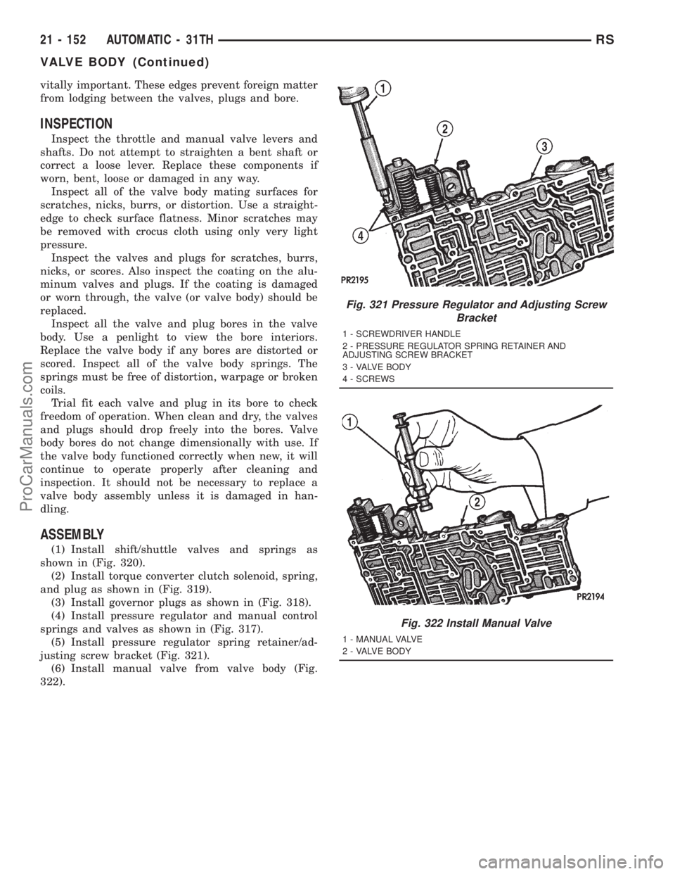
(5) Install pressure regulator spring retainer/ad-
justing screw bracket (Fig. 321).
(6) Install manual valve from valve body (Fig.
322).
Fig. 321 Pressure Regulator and Adjusting Screw
Bracket
1 - SCREWDRIVER HANDLE
2 - PRESSURE REGULATOR SPRING RETAINER AND
ADJUSTING SCREW BRACKET
3 - VALVE BODY
4 - SCREWS
Fig. 322 Install Manual Valve
1 - MANUAL VALVE
2 - VALVE BODY
21 - 152 AUTOMATIC - 31THRS
VALVE BODY (Continued)
ProCarManuals.com
Page 1656 of 2321
VALVE BODY
DESCRIPTION..........................289
OPERATION............................290
REMOVAL.............................290DISASSEMBLY..........................292
ASSEMBLY............................296
INSTALLATION..........................301
AUTOMATIC - 41TE
TRANSAXLE IDENTIFICATION
DESCRIPTION
The 41TE (Fig. 1) is a four-speed transaxle that is
a conventional hydraulic/mechanical assembly with
an integral differential, and is controlled with adap-
tive electronic controls and monitors. The hydraulic
system of the transaxle consists of the transaxle
fluid, fluid passages, hydraulic valves, and various
line pressure control components. An input clutch
assembly which houses the underdrive, overdrive,
and reverse clutches is used. It also utilizes separate
holding clutches: 2nd/4th gear and Low/Reverse. The
primary mechanical components of the transaxle con-
sist of the following:
²Three multiple disc input clutches
²Two multiple disc holding clutches
²Four hydraulic accumulators
²Two planetary gear sets
²Hydraulic oil pump
²Valve body
²Solenoid/Pressure switch assembly
²Integral differential assembly
Control of the transaxle is accomplished by fully
adaptive electronics. Optimum shift scheduling is
accomplished through continuous real-time sensor
feedback information provided to the Transmission
Control Module (TCM).
The TCM is the heart of the electronic control sys-
tem and relies on information from various direct
and indirect inputs (sensors, switches, etc.) to deter-
mine driver demand and vehicle operating condi-
tions. With this information, the TCM can calculate
and perform timely and quality shifts through vari-
ous output or control devices (solenoid pack, trans-
mission control relay, etc.).
The TCM also performs certain self-diagnostic
functions and provides comprehensive information
(sensor data, DTC's, etc.) which is helpful in proper
diagnosis and repair. This information can be viewed
with the DRB scan tool.
The 41TE transaxle identification code is a series
of digits printed on a bar-code label that is fixed to
the transaxle case as shown in (Fig. 2).For example, the identification code K 821 1125
1316 can be broken down as follows:
²K = Kokomo Transmission Plant
²821 = Last three digits of the transaxle part
number
²1125 = Build date
²1316 = Build sequence number
If the tag is not legible or missing, the ªPKº num-
ber, which is stamped into the transaxle case behind
the transfer gear cover, can be referred to for identi-
fication. This number differs slightly in that it con-
tains the entire transaxle part number, rather than
the last three digits.
OPERATION
Transmission output is directed to an integral dif-
ferential by a transfer gear system in the following
input-to-output ratios:
First...............................2.84 : 1
Second.............................1.57 : 1
Third..............................1.00 : 1
Overdrive...........................0.69 : 1
Reverse............................2.21 : 1
DIAGNOSIS AND TESTING - 41TE TRANSAXLE
GENERAL DIAGNOSIS
NOTE: Before attempting any repair on a 41TE four-
speed automatic transaxle, check for diagnostic
trouble codes (DTC's) using the DRB scan tool.
Refer to the Transmission Diagnostic Procedures
Manual.
Transaxle malfunctions may be caused by these
general conditions:
²Poor engine performance
²Improper adjustments
²Hydraulic malfunctions
²Mechanical malfunctions
²Electronic malfunctions
Diagnosis of these problems should always begin
by checking the easily accessible variables: fluid level
and condition, gearshift cable adjustment. Then per-
form a road test to determine if the problem has been
corrected or that more diagnosis is necessary. If the
problem persists after the preliminary tests and cor-
rections are completed, hydraulic pressure checks
should be performed.
RSAUTOMATIC - 41TE21 - 159
ProCarManuals.com
Page 1782 of 2321
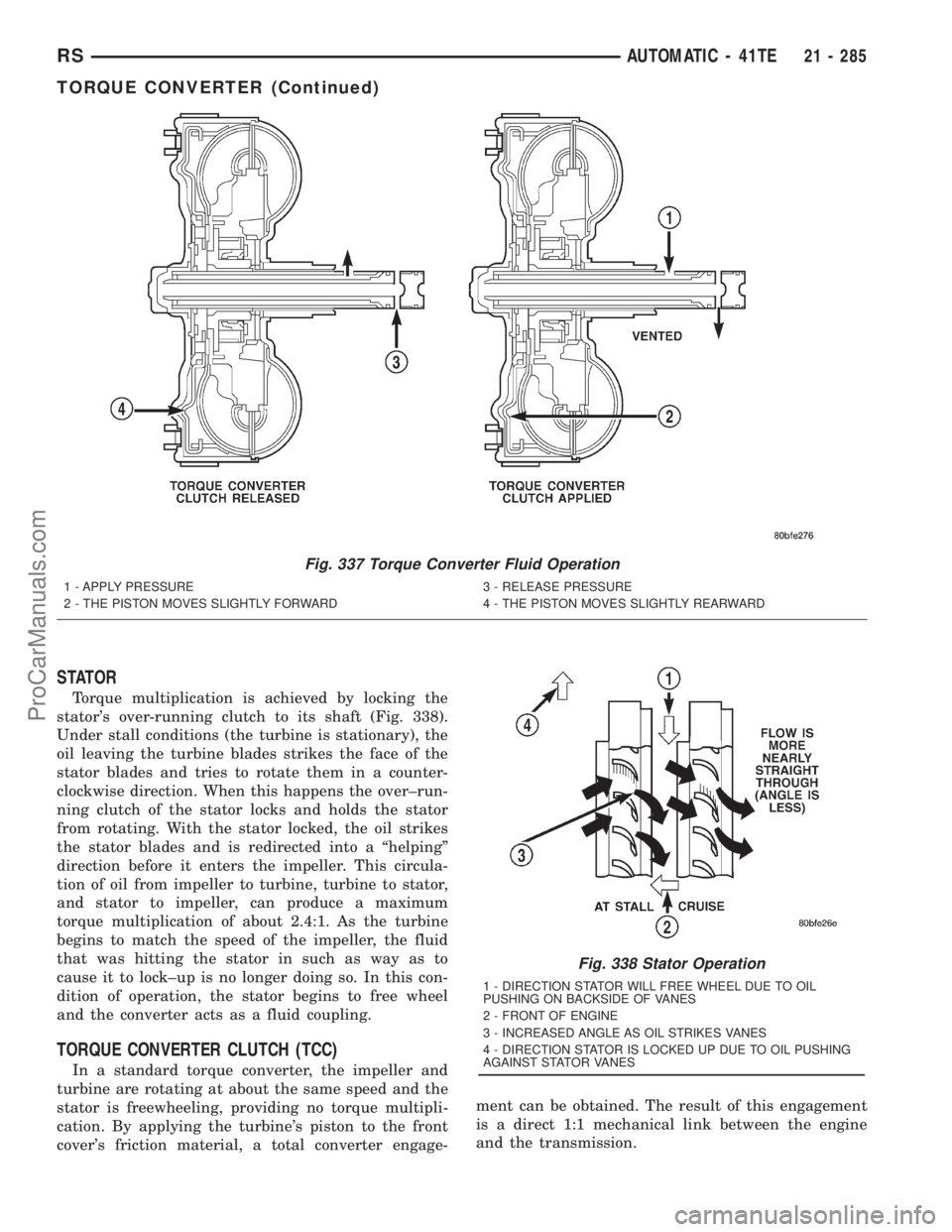
STATOR
Torque multiplication is achieved by locking the
stator's over-running clutch to its shaft (Fig. 338).
Under stall conditions (the turbine is stationary), the
oil leaving the turbine blades strikes the face of the
stator blades and tries to rotate them in a counter-
clockwise direction. When this happens the over±run-
ning clutch of the stator locks and holds the stator
from rotating. With the stator locked, the oil strikes
the stator blades and is redirected into a ªhelpingº
direction before it enters the impeller. This circula-
tion of oil from impeller to turbine, turbine to stator,
and stator to impeller, can produce a maximum
torque multiplication of about 2.4:1. As the turbine
begins to match the speed of the impeller, the fluid
that was hitting the stator in such as way as to
cause it to lock±up is no longer doing so. In this con-
dition of operation, the stator begins to free wheel
and the converter acts as a fluid coupling.
TORQUE CONVERTER CLUTCH (TCC)
In a standard torque converter, the impeller and
turbine are rotating at about the same speed and the
stator is freewheeling, providing no torque multipli-
cation. By applying the turbine's piston to the front
cover's friction material, a total converter engage-ment can be obtained. The result of this engagement
is a direct 1:1 mechanical link between the engine
and the transmission.
Fig. 337 Torque Converter Fluid Operation
1 - APPLY PRESSURE
2 - THE PISTON MOVES SLIGHTLY FORWARD3 - RELEASE PRESSURE
4 - THE PISTON MOVES SLIGHTLY REARWARD
Fig. 338 Stator Operation
1 - DIRECTION STATOR WILL FREE WHEEL DUE TO OIL
PUSHING ON BACKSIDE OF VANES
2 - FRONT OF ENGINE
3 - INCREASED ANGLE AS OIL STRIKES VANES
4 - DIRECTION STATOR IS LOCKED UP DUE TO OIL PUSHING
AGAINST STATOR VANES
RSAUTOMATIC - 41TE21 - 285
TORQUE CONVERTER (Continued)
ProCarManuals.com
Page 1783 of 2321
The engagement and disengagement of the TCC
are automatic and controlled by the Powertrain Con-
trol Module (PCM). The engagement cannot be acti-
vated in the lower gears because it eliminates the
torque multiplication effect of the torque converter
necessary for acceleration. Inputs that determine
clutch engagement are: coolant temperature, vehicle
speed and throttle position. The torque converter
clutch is engaged by the clutch solenoid on the valve
body. The clutch will engage at approximately 56
km/h (35 mph) with light throttle, after the shift to
third gear.
REMOVAL
NOTE: If torque conveter assembly is being
replaced, it is necessary to restart the TCC Break-In
Strategy. (Refer to 8 - ELECTRICAL/ELECTRONIC
CONTROL MODULES/TRANSMISSION CONTROL
MODULE - STANDARD PROCEDURE)
(1) Remove transmission and torque converter
from vehicle. (Refer to 21 - TRANSMISSION/TRANS-
AXLE/AUTOMATIC - 41TE - REMOVAL)
(2) Place a suitable drain pan under the converter
housing end of the transmission.
CAUTION: Verify that transmission is secure on the
lifting device or work surface, the center of gravity
of the transmission will shift when the torque con-
verter is removed creating an unstable condition.
The torque converter is a heavy unit. Use caution
when separating the torque converter from the
transmission.
(3) Pull the torque converter forward until the cen-
ter hub clears the oil pump seal.
(4) Separate the torque converter from the trans-
mission.
INSTALLATION
NOTE: If torque conveter is being replaced, it is
necessary to restart the TCC Break-In Strategy.
(Refer to 8 - ELECTRICAL/ELECTRONIC CONTROL
MODULES/TRANSMISSION CONTROL MODULE -
STANDARD PROCEDURE)
Check converter hub and drive notches for sharp
edges, burrs, scratches, or nicks. Polish the hub and
notches with 320/400 grit paper or crocus cloth if nec-
essary. The hub must be smooth to avoid damaging
the pump seal at installation.
(1) Lubricate converter hub and oil pump seal lip
with transmission fluid.
(2) Place torque converter in position on transmis-
sion.CAUTION: Do not damage oil pump seal or bushing
while inserting torque converter into the front of the
transmission.
(3) Align torque converter to oil pump seal open-
ing.
(4) Insert torque converter hub into oil pump.
(5) While pushing torque converter inward, rotate
converter until converter is fully seated in the oil
pump gears.
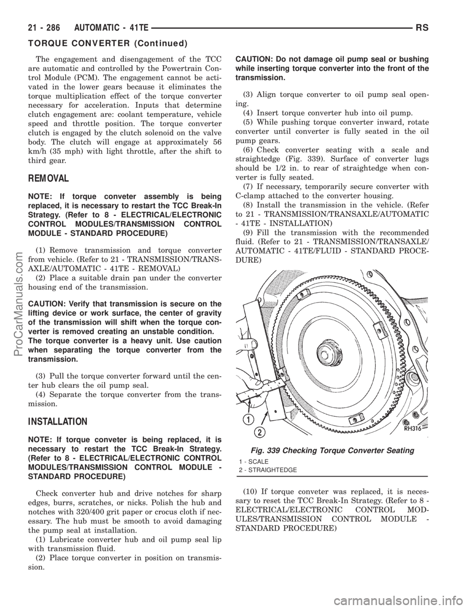
(6) Check converter seating with a scale and
straightedge (Fig. 339). Surface of converter lugs
should be 1/2 in. to rear of straightedge when con-
verter is fully seated.
(7) If necessary, temporarily secure converter with
C-clamp attached to the converter housing.
(8) Install the transmission in the vehicle. (Refer
to 21 - TRANSMISSION/TRANSAXLE/AUTOMATIC
- 41TE - INSTALLATION)
(9) Fill the transmission with the recommended
fluid. (Refer to 21 - TRANSMISSION/TRANSAXLE/
AUTOMATIC - 41TE/FLUID - STANDARD PROCE-
DURE)
(10) If torque conveter was replaced, it is neces-
sary to reset the TCC Break-In Strategy. (Refer to 8 -
ELECTRICAL/ELECTRONIC CONTROL MOD-
ULES/TRANSMISSION CONTROL MODULE -
STANDARD PROCEDURE)
Fig. 339 Checking Torque Converter Seating
1 - SCALE
2 - STRAIGHTEDGE
21 - 286 AUTOMATIC - 41TERS
TORQUE CONVERTER (Continued)
ProCarManuals.com
Page 1787 of 2321
OPERATION
NOTE: Refer to the Hydraulic Schematics for a
visual aid in determining valve location, operation
and design.
REGULATOR VALVE
The regulator valve controls hydraulic pressure in
the transaxle. It receives unregulated pressure from
the pump, which works against spring tension to
maintain oil at specific pressures. A system of sleeves
and ports allows the regulator valve to work at one of
three predetermined pressure levels. Regulated oil
pressure is also referred to as ªline pressure.º
SOLENOID SWITCH VALVE
The solenoid switch valve controls line pressure
from the LR/CC solenoid. In one position, it allows
the low/reverse clutch to be pressurized. In the other,
it directs line pressure to the converter control and
converter clutch valves.
MANUAL VALVE
The manual valve is operated by the mechanical
shift linkage. Its primary responsibility is to send
line pressure to the appropriate hydraulic circuits
and solenoids. The valve has three operating ranges
or positions.
CONVERTER CLUTCH SWITCH VALVE
The main responsibility of the converter clutch
switch valve is to control hydraulic pressure applied
to the front (off) side of the converter clutch piston.
Line pressure from the regulator valve is fed to the
torque converter regulator valve, where it passes
through the valve, and is slightly regulated. The
pressure is then directed to the converter clutch
switch valve and to the front side of the converter
clutch piston. This pressure pushes the piston back
and disengages the converter clutch.
CONVERTER CLUTCH CONTROL VALVE
The converter clutch control valve controls the
back (on) side of the torque converter clutch. When
the TCM energizes or modulates the LR/CC solenoid
to apply the converter clutch piston, both the con-
verter clutch control valve and the converter control
valve move, allowing pressure to be applied to the
back side of the clutch.
T/C REGULATOR VALVE
The torque converter regulator valve slightly regu-
lates the flow of fluid to the torque converter.
LOW/REVERSE SWITCH VALVE
The low/reverse clutch is applied from different
sources, depending on whether low (1st) gear or
reverse is selected. The low/reverse switch valve
alternates positions depending on from which direc-
tion fluid pressure is applied. By design, when the
valve is shifted by fluid pressure from one channel,
the opposing channel is blocked. The switch valve
alienates the possibility of a sticking ball check, thus
providing consistent application of the low/reverse
clutch under all operating conditions.
REMOVAL
NOTE: If valve body is replaced or reconditioned,
the TCM Quick Learn Procedure must be per-
formed. (Refer to 8 - ELECTRICAL/ELECTRONIC
CONTROL MODULES/TRANSMISSION CONTROL
MODULE - STANDARD PROCEDURE)
(1) Disconnect battery negative cable.
(2) Disconnect gearshift cable from manual valve
lever.
(3) Remove manual valve lever from manual shaft.
(4) Raise vehicle on hoist.
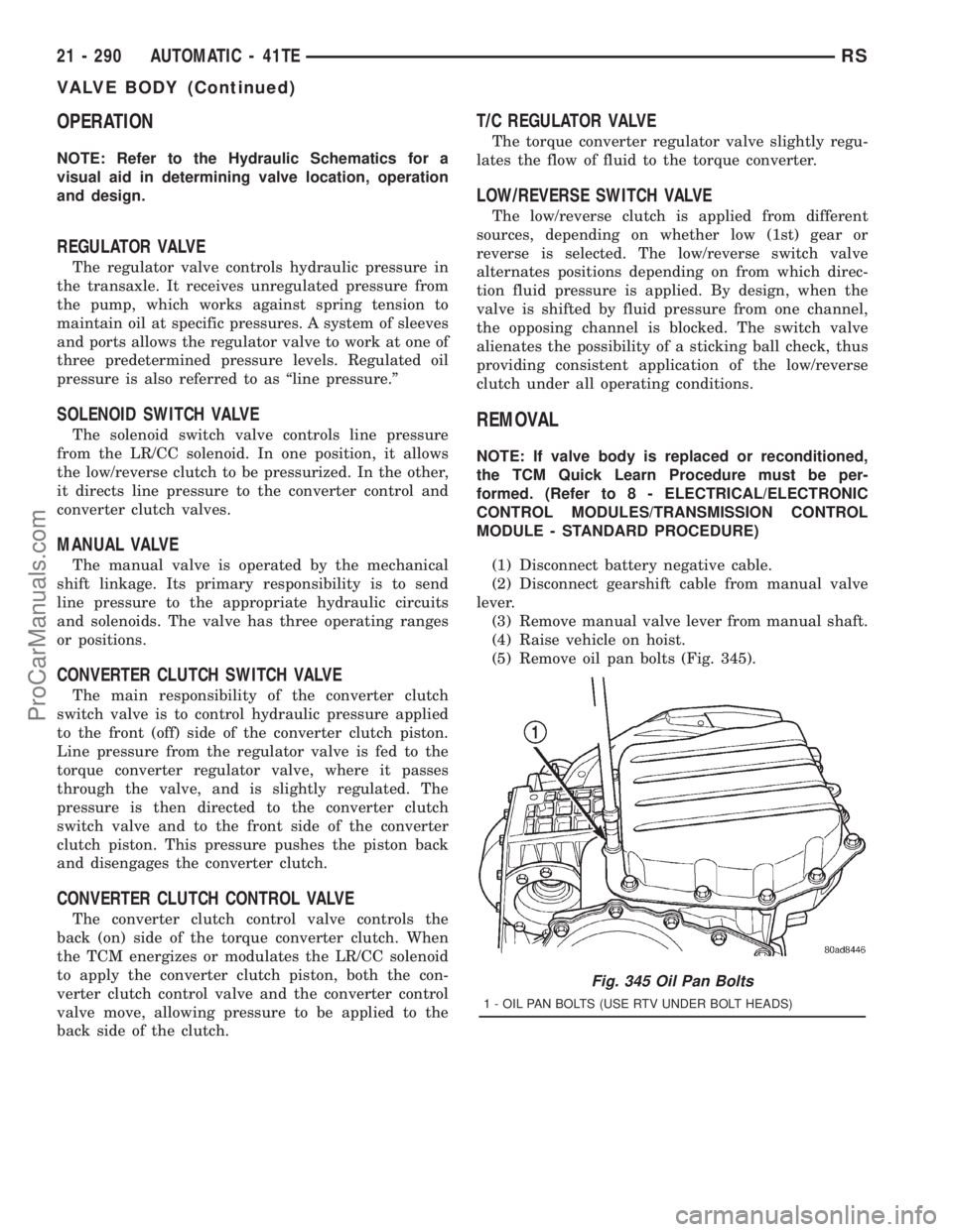
(5) Remove oil pan bolts (Fig. 345).
Fig. 345 Oil Pan Bolts
1 - OIL PAN BOLTS (USE RTV UNDER BOLT HEADS)
21 - 290 AUTOMATIC - 41TERS
VALVE BODY (Continued)
ProCarManuals.com
Page 1829 of 2321
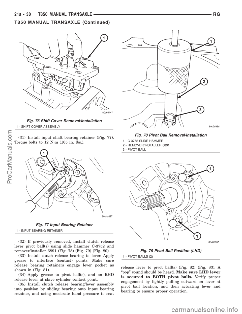
(31) Install input shaft bearing retainer (Fig. 77).
Torque bolts to 12 N´m (105 in. lbs.).
(32) If previously removed, install clutch release
lever pivot ball(s) using slide hammer C-3752 and
remover/installer 6891 (Fig. 78) (Fig. 79) (Fig. 80).
(33) Install clutch release bearing to lever. Apply
grease to interface (contact) points. Make sure
release bearing retainers engage lever pocket as
shown in (Fig. 81).
(34) Apply grease to pivot ball(s), and on RHD
release lever at slave cylinder contact point.
(35) Install clutch release bearing/lever assembly
into position by sliding bearing onto input bearing
retainer, and using moderate hand pressure to seatrelease lever to pivot ball(s) (Fig. 82) (Fig. 83). A
ªpopº sound should be heard.Make sure LHD lever
is secured to BOTH pivot balls.Verify proper
engagement by lightly pulling outward on lever at
pivot ball location, and then actuating lever and
bearing to ensure proper operation.
Fig. 76 Shift Cover Removal/Installation
1 - SHIFT COVER ASSEMBLY
Fig. 77 Input Bearing Retainer
1 - INPUT BEARING RETAINER
Fig. 78 Pivot Ball Removal/Installation
1 - C-3752 SLIDE HAMMER
2 - REMOVER/INSTALLER 6891
3 - PIVOT BALL
Fig. 79 Pivot Ball Position (LHD)
1 - PIVOT BALLS (2)
21a - 30 T850 MANUAL TRANSAXLERG
T850 MANUAL TRANSAXLE (Continued)
ProCarManuals.com