2001 DODGE TOWN AND COUNTRY light
[x] Cancel search: lightPage 1354 of 2321
(4) Skirt wear should not exceed 0.1 mm (.00039
in.).
(5) The clearance between the cylinder liner and
piston should not exceed 0.065-0.083 mm
(.0025-.0032 in.).
(6) Make sure the weight of the pistons does not
differ by more than 5 g.
CONNECTING RODS
(1) Assemble bearing shells and bearing caps to
their respective connecting rods ensuring that the
serrations on the cap and reference marks are
aligned.
(2) Tighten bearing cap bolts to 29 N´m (21 ft. lbs.)
plus 60É.
(3) Check and record internal diameter of crank
end of connecting rod.
NOTE: When changing connecting rods, all four
must have the same weight and be stamped with
the same number. Replacement connecting rods
will only be supplied in sets of four.
Connecting rods are supplied in sets of four since
they all must be of the same weight category. Max
allowable weight difference is 18 gr.
NOTE: On one side of the big end of the con-rod
there is a two-digit number which refers to the
weight category. On the other side of the big end
there is a four digit number on both the rod and the
cap. These numbers must both face the injection
pump side of the block. Lightly heat the piston in
oven. Insert piston pin in position and secure it
with provided snap rings.
The Four digit numbers marked on con rod
big end and rod cap must be on the same side
as the injection pump.After having coated threads
with Molyguard, tighten con rod bolts to 29 N´m (21
ft. lbs.) plus 60É.
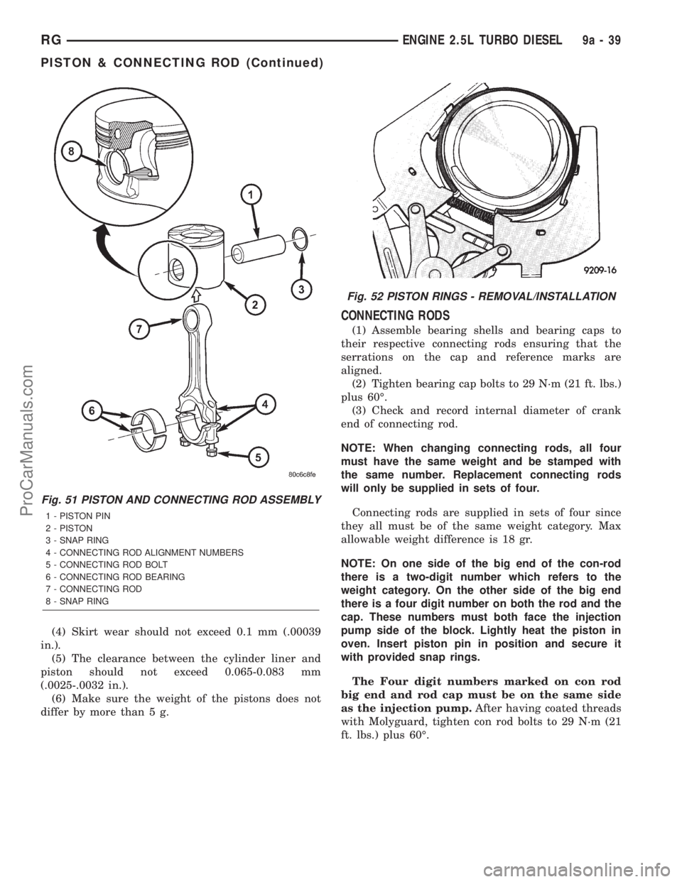
Fig. 51 PISTON AND CONNECTING ROD ASSEMBLY
1 - PISTON PIN
2 - PISTON
3 - SNAP RING
4 - CONNECTING ROD ALIGNMENT NUMBERS
5 - CONNECTING ROD BOLT
6 - CONNECTING ROD BEARING
7 - CONNECTING ROD
8 - SNAP RING
Fig. 52 PISTON RINGS - REMOVAL/INSTALLATION
RGENGINE 2.5L TURBO DIESEL9a-39
PISTON & CONNECTING ROD (Continued)
ProCarManuals.com
Page 1384 of 2321
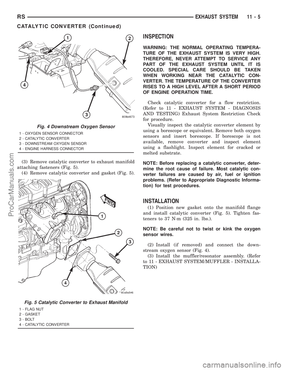
(3) Remove catalytic converter to exhaust manifold
attaching fasteners (Fig. 5).
(4) Remove catalytic converter and gasket (Fig. 5).
INSPECTION
WARNING: THE NORMAL OPERATING TEMPERA-
TURE OF THE EXHAUST SYSTEM IS VERY HIGH.
THEREFORE, NEVER ATTEMPT TO SERVICE ANY
PART OF THE EXHAUST SYSTEM UNTIL IT IS
COOLED. SPECIAL CARE SHOULD BE TAKEN
WHEN WORKING NEAR THE CATALYTIC CON-
VERTER. THE TEMPERATURE OF THE CONVERTER
RISES TO A HIGH LEVEL AFTER A SHORT PERIOD
OF ENGINE OPERATION TIME.
Check catalytic converter for a flow restriction.
(Refer to 11 - EXHAUST SYSTEM - DIAGNOSIS
AND TESTING) Exhaust System Restriction Check
for procedure.
Visually inspect the catalytic converter element by
using a borescope or equivalent. Remove both oxygen
sensors and insert borescope. If borescope is not
available, remove converter and inspect element
using a flashlight. Inspect element for cracked or
melted substrate.
NOTE: Before replacing a catalytic converter, deter-
mine the root cause of failure. Most catalytic con-
verter failures are caused by air, fuel or ignition
problems. (Refer to Appropriate Diagnostic Informa-
tion) for test procedures.
INSTALLATION
(1) Position new gasket onto the manifold flange
and install catalytic converter (Fig. 5). Tighten fas-
teners to 37 N´m (325 in. lbs.).
NOTE: Be careful not to twist or kink the oxygen
sensor wires.
(2) Install (if removed) and connect the down-
stream oxygen sensor (Fig. 4).
(3) Install the muffler/resonator assembly. (Refer
to 11 - EXHAUST SYSTEM/MUFFLER - INSTALLA-
TION)
Fig. 4 Downstream Oxygen Sensor
1 - OXYGEN SENSOR CONNECTOR
2 - CATALYTIC CONVERTER
3 - DOWNSTREAM OXYGEN SENSOR
4 - ENGINE HARNESS CONNECTOR
Fig. 5 Catalytic Converter to Exhaust Manifold
1 - FLAG NUT
2 - GASKET
3 - BOLT
4 - CATALYTIC CONVERTER
RSEXHAUST SYSTEM11-5
CATALYTIC CONVERTER (Continued)
ProCarManuals.com
Page 1386 of 2321
Avoid application of rust prevention com-
pounds or undercoating materials to exhaust
system floor pan heat shields on cars so
equipped. Light over spray near the edges is
permitted. Application of coating will greatly
reduce the efficiency of the heat shields result-
ing in excessive floor pan temperatures and
objectionable fumes.
REMOVAL
(1) Raise vehicle on hoist.
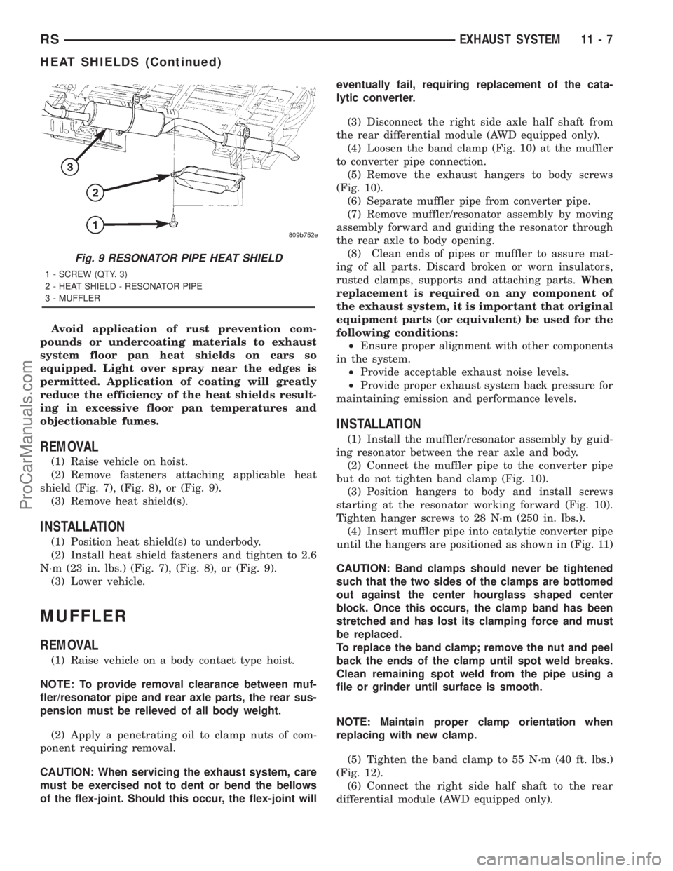
(2) Remove fasteners attaching applicable heat
shield (Fig. 7), (Fig. 8), or (Fig. 9).
(3) Remove heat shield(s).
INSTALLATION
(1) Position heat shield(s) to underbody.
(2) Install heat shield fasteners and tighten to 2.6
N´m (23 in. lbs.) (Fig. 7), (Fig. 8), or (Fig. 9).
(3) Lower vehicle.
MUFFLER
REMOVAL
(1) Raise vehicle on a body contact type hoist.
NOTE: To provide removal clearance between muf-
fler/resonator pipe and rear axle parts, the rear sus-
pension must be relieved of all body weight.
(2) Apply a penetrating oil to clamp nuts of com-
ponent requiring removal.
CAUTION: When servicing the exhaust system, care
must be exercised not to dent or bend the bellows
of the flex-joint. Should this occur, the flex-joint willeventually fail, requiring replacement of the cata-
lytic converter.
(3) Disconnect the right side axle half shaft from
the rear differential module (AWD equipped only).
(4) Loosen the band clamp (Fig. 10) at the muffler
to converter pipe connection.
(5) Remove the exhaust hangers to body screws
(Fig. 10).
(6) Separate muffler pipe from converter pipe.
(7) Remove muffler/resonator assembly by moving
assembly forward and guiding the resonator through
the rear axle to body opening.
(8) Clean ends of pipes or muffler to assure mat-
ing of all parts. Discard broken or worn insulators,
rusted clamps, supports and attaching parts.When
replacement is required on any component of
the exhaust system, it is important that original
equipment parts (or equivalent) be used for the
following conditions:
²Ensure proper alignment with other components
in the system.
²Provide acceptable exhaust noise levels.
²Provide proper exhaust system back pressure for
maintaining emission and performance levels.
INSTALLATION
(1) Install the muffler/resonator assembly by guid-
ing resonator between the rear axle and body.
(2) Connect the muffler pipe to the converter pipe
but do not tighten band clamp (Fig. 10).
(3) Position hangers to body and install screws
starting at the resonator working forward (Fig. 10).
Tighten hanger screws to 28 N´m (250 in. lbs.).
(4) Insert muffler pipe into catalytic converter pipe
until the hangers are positioned as shown in (Fig. 11)
CAUTION: Band clamps should never be tightened
such that the two sides of the clamps are bottomed
out against the center hourglass shaped center
block. Once this occurs, the clamp band has been
stretched and has lost its clamping force and must
be replaced.
To replace the band clamp; remove the nut and peel
back the ends of the clamp until spot weld breaks.
Clean remaining spot weld from the pipe using a
file or grinder until surface is smooth.
NOTE: Maintain proper clamp orientation when
replacing with new clamp.
(5) Tighten the band clamp to 55 N´m (40 ft. lbs.)
(Fig. 12).
(6) Connect the right side half shaft to the rear
differential module (AWD equipped only).
Fig. 9 RESONATOR PIPE HEAT SHIELD
1 - SCREW (QTY. 3)
2 - HEAT SHIELD - RESONATOR PIPE
3 - MUFFLER
RSEXHAUST SYSTEM11-7
HEAT SHIELDS (Continued)
ProCarManuals.com
Page 1388 of 2321
EXHAUST SYSTEM AND TURBOCHARGER
TABLE OF CONTENTS
page page
EXHAUST SYSTEM AND TURBOCHARGER
DESCRIPTION............................1
SPECIFICATIONS.........................1
TURBOCHARGER SYSTEM
DESCRIPTION............................2
OPERATION.............................2
TURBOCHARGER
REMOVAL...............................4CLEANING...............................5
INSTALLATION............................5
HEAT SHIELDS
REMOVAL...............................5
INSTALLATION............................6
EXHAUST SYSTEM AND
TURBOCHARGER
DESCRIPTION
The basic exhaust system consists of an engine
exhaust manifold, turbocharger, exhaust down pipe,
exhaust pipe, exhaust heat shield(s), muffler and
exhaust tailpipe
The exhaust system uses a single muffler.
The exhaust system must be properly aligned to
prevent stress, leakage and body contact. If the sys-
tem contacts any body panel, it will transfer objec-
tionable noises originating from the engine to the
body.
When inspecting an exhaust system, critically
inspect for cracked or loose joints, stripped screw orbolt threads, corrosion damage and worn, cracked or
broken hangers. Replace all components that are
badly corroded or damaged. DO NOT attempt to
repair.
When replacement is required, use original equip-
ment parts (or equivalent). This will assure proper
alignment and provide acceptable exhaust noise lev-
els.
CAUTION: Avoid application of rust prevention com-
pounds or undercoating materials to exhaust sys-
tem floor pan exhaust heat shields. Light overspray
near the edges is permitted. Application of coating
will result in excessive floor pan temperatures and
objectionable fumes.
SPECIFICATIONS
SPECIFICATIONS - TORQUE
2.5L DIESEL - TORQUE SPECIFICATIONS
DESCRIPTION N´m Ft. Lbs. In. Lbs.
Turbocharger Oil Feed
Line Fitting24.5 18 215
Exhaust Manifold Nuts 32.4 24 Ð
Exhaust Manifold Heat
shield Bolts27.5 21 Ð
Turbocharger Downpipe
Nuts32.4 24 Ð
Turbocharger Bracket
Bolts47.1 35 Ð
Turbocharger to Exhaust
Manifold Nuts32.4 24 Ð
RGEXHAUST SYSTEM AND TURBOCHARGER11a-1
ProCarManuals.com
Page 1395 of 2321
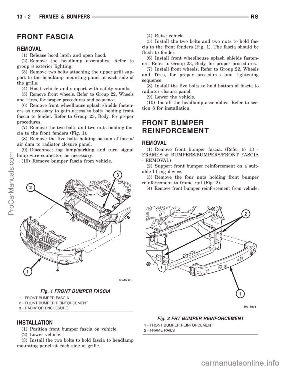
FRONT FASCIA
REMOVAL
(1) Release hood latch and open hood.
(2) Remove the headlamp assemblies. Refer to
group 8 exterior lighting.
(3) Remove two bolts attaching the upper grill sup-
port to the headlamp mounting panel at each side of
the grille.
(4) Hoist vehicle and support with safety stands.
(5)
Remove front wheels. Refer to Group 22, Wheels
and Tires, for proper procedures and sequence.
(6) Remove front wheelhouse splash shields fasten-
ers as necessary to gain access to bolts holding front
fascia to fender. Refer to Group 23, Body, for proper
procedures.
(7) Remove the two bolts and two nuts holding fas-
cia to the front fenders (Fig. 1).
(8) Remove the five bolts holding bottom of fascia/
air dam to radiator closure panel.
(9) Disconnect fog lamp/parking and turn signal
lamp wire connector, as necessary.
(10) Remove bumper fascia from vehicle.
INSTALLATION
(1) Position front bumper fascia on vehicle.
(2) Lower vehicle.
(3) Install the two bolts to hold fascia to headlamp
mounting panel at each side of grille.(4) Raise vehicle.
(5) Install the two bolts and two nuts to hold fas-
cia to the front fenders (Fig. 1). The fascia should be
flush to fender.
(6) Install front wheelhouse splash shields fasten-
ers. Refer to Group 23, Body, for proper procedures.
(7) Install front wheels. Refer to Group 22, Wheels
and Tires, for proper procedures and tightening
sequence.
(8) Install the five bolts to hold bottom of fascia to
radiator closure panel.
(9) Lower the vehicle.
(10) Install the headlamp assemblies. Refer to sec-
tion 8 for installation.
FRONT BUMPER
REINFORCEMENT
REMOVAL
(1) Remove front bumper fascia. (Refer to 13 -
FRAMES & BUMPERS/BUMPERS/FRONT FASCIA
- REMOVAL)
(2) Support front bumper reinforcement on a suit-
able lifting device.
(3) Remove the four nuts holding front bumper
reinforcement to frame rail (Fig. 2).
(4) Remove front bumper reinforcement from vehicle.
Fig. 1 FRONT BUMPER FASCIA
1 - FRONT BUMPER FASCIA
2 - FRONT BUMPER REINFORCEMENT
3 - RADIATOR ENCLOSURE
Fig. 2 FRT BUMPER REINFORCEMENT
1 - FRONT BUMPER REINFORCEMENT
2 - FRAME RAILS
13 - 2 FRAMES & BUMPERSRS
ProCarManuals.com
Page 1410 of 2321
(2) Pull off the locking wedge.
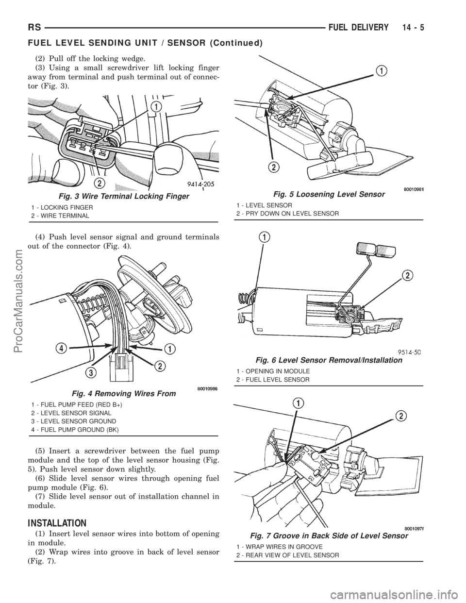
(3) Using a small screwdriver lift locking finger
away from terminal and push terminal out of connec-
tor (Fig. 3).
(4) Push level sensor signal and ground terminals
out of the connector (Fig. 4).
(5) Insert a screwdriver between the fuel pump
module and the top of the level sensor housing (Fig.
5). Push level sensor down slightly.
(6) Slide level sensor wires through opening fuel
pump module (Fig. 6).
(7) Slide level sensor out of installation channel in
module.
INSTALLATION
(1) Insert level sensor wires into bottom of opening
in module.
(2) Wrap wires into groove in back of level sensor
(Fig. 7).
Fig. 3 Wire Terminal Locking Finger
1 - LOCKING FINGER
2 - WIRE TERMINAL
Fig. 4 Removing Wires From
1 - FUEL PUMP FEED (RED B+)
2 - LEVEL SENSOR SIGNAL
3 - LEVEL SENSOR GROUND
4 - FUEL PUMP GROUND (BK)
Fig. 5 Loosening Level Sensor
1 - LEVEL SENSOR
2 - PRY DOWN ON LEVEL SENSOR
Fig. 6 Level Sensor Removal/Installation
1 - OPENING IN MODULE
2 - FUEL LEVEL SENSOR
Fig. 7 Groove in Back Side of Level Sensor
1 - WRAP WIRES IN GROOVE
2 - REAR VIEW OF LEVEL SENSOR
RSFUEL DELIVERY14-5
FUEL LEVEL SENDING UNIT / SENSOR (Continued)
ProCarManuals.com
Page 1412 of 2321
The pressure regulator is a mechanical device that
is NOT controlled by the PCM or engine vacuum.
REMOVAL
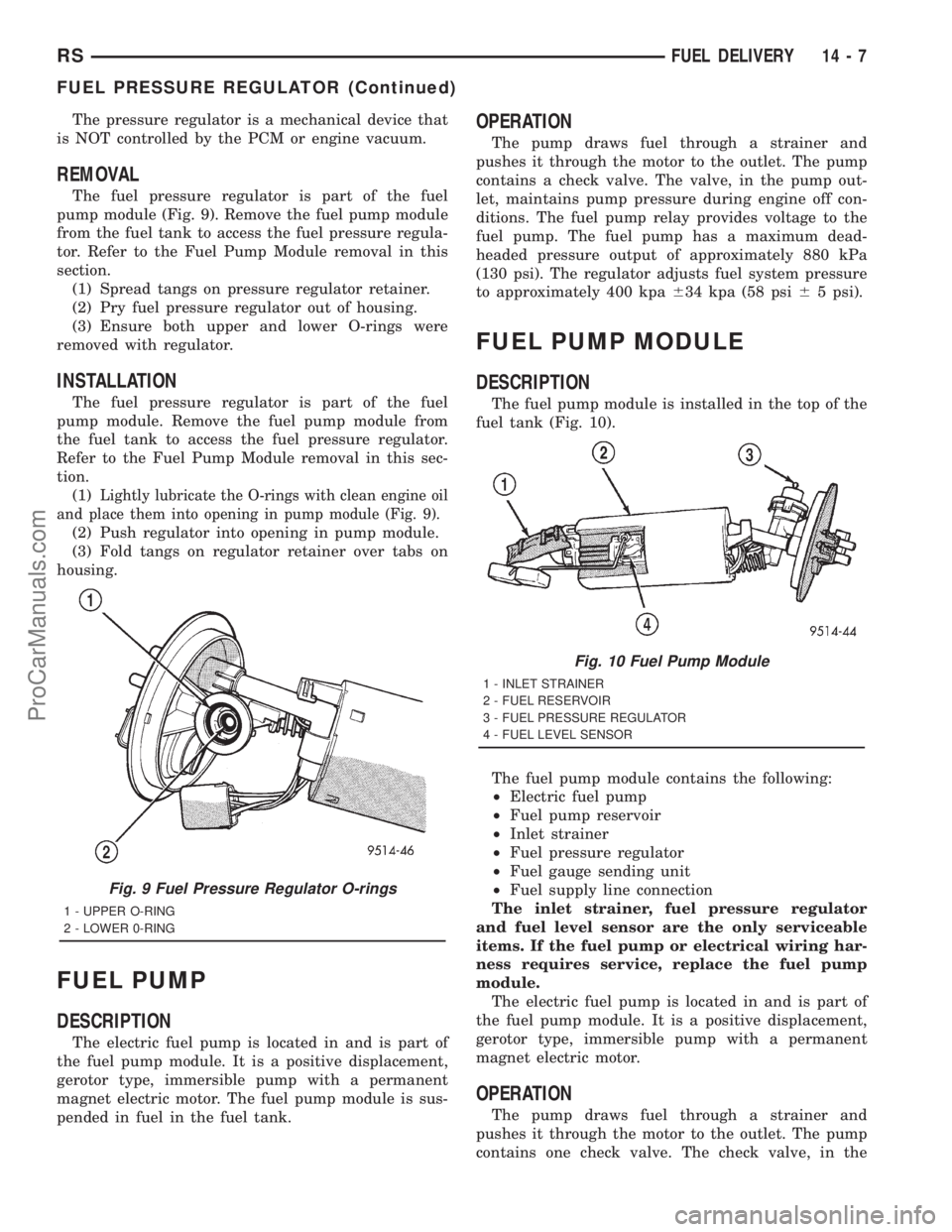
The fuel pressure regulator is part of the fuel
pump module (Fig. 9). Remove the fuel pump module
from the fuel tank to access the fuel pressure regula-
tor. Refer to the Fuel Pump Module removal in this
section.
(1) Spread tangs on pressure regulator retainer.
(2) Pry fuel pressure regulator out of housing.
(3) Ensure both upper and lower O-rings were
removed with regulator.
INSTALLATION
The fuel pressure regulator is part of the fuel
pump module. Remove the fuel pump module from
the fuel tank to access the fuel pressure regulator.
Refer to the Fuel Pump Module removal in this sec-
tion.
(1)
Lightly lubricate the O-rings with clean engine oil
and place them into opening in pump module (Fig. 9).
(2) Push regulator into opening in pump module.
(3) Fold tangs on regulator retainer over tabs on
housing.
FUEL PUMP
DESCRIPTION
The electric fuel pump is located in and is part of
the fuel pump module. It is a positive displacement,
gerotor type, immersible pump with a permanent
magnet electric motor. The fuel pump module is sus-
pended in fuel in the fuel tank.
OPERATION
The pump draws fuel through a strainer and
pushes it through the motor to the outlet. The pump
contains a check valve. The valve, in the pump out-
let, maintains pump pressure during engine off con-
ditions. The fuel pump relay provides voltage to the
fuel pump. The fuel pump has a maximum dead-
headed pressure output of approximately 880 kPa
(130 psi). The regulator adjusts fuel system pressure
to approximately 400 kpa634 kpa (58 psi65 psi).
FUEL PUMP MODULE
DESCRIPTION
The fuel pump module is installed in the top of the
fuel tank (Fig. 10).
The fuel pump module contains the following:
²Electric fuel pump
²Fuel pump reservoir
²Inlet strainer
²Fuel pressure regulator
²Fuel gauge sending unit
²Fuel supply line connection
The inlet strainer, fuel pressure regulator
and fuel level sensor are the only serviceable
items. If the fuel pump or electrical wiring har-
ness requires service, replace the fuel pump
module.
The electric fuel pump is located in and is part of
the fuel pump module. It is a positive displacement,
gerotor type, immersible pump with a permanent
magnet electric motor.
OPERATION
The pump draws fuel through a strainer and
pushes it through the motor to the outlet. The pump
contains one check valve. The check valve, in the
Fig. 9 Fuel Pressure Regulator O-rings
1 - UPPER O-RING
2 - LOWER 0-RING
Fig. 10 Fuel Pump Module
1 - INLET STRAINER
2 - FUEL RESERVOIR
3 - FUEL PRESSURE REGULATOR
4 - FUEL LEVEL SENSOR
RSFUEL DELIVERY14-7
FUEL PRESSURE REGULATOR (Continued)
ProCarManuals.com
Page 1415 of 2321
(3) Put the tip of each injector into their ports.
Push the assembly into place until the injectors are
seated in the ports.
(4) Install the fuel rail mounting bolts. Tighten
bolts to 22 N´m (200 in. lbs.) torque.
(5) Remove covering on lower intake manifold and
clean surface.
(6) Install the Upper Intake Manifold, refer to
Engine/Manifolds/Upper Intake for more information.
(7) Install fuel hose quick connector fitting to chas-
sis tubes.Refer to Fuel Hoses, Clamps and
Quick Connect Fittings in this Section.Push the
fitting onto the chassis tube until it clicks into place.
Pull on the fitting to ensure complete insertion.
(8) Connect negative cable to battery.
(9) Use the DRBIIItscan tool to pressurize the
fuel system. Check for leaks.
FUEL TANK
DESCRIPTION
The fuel tank is constructed of a plastic material.
Its main functions are for fuel storage and for place-
ment of the fuel pump module. The tank is made
from High density Polyethylene (HDPE) material.If
equipped with ORVR (Onboard Refueling Vapor
Recovery) it has been added to the fuel tank to con-
trol refueling vapor emissions.
OPERATION
All models pass a full 360 degree rollover test
without fuel leakage. To accomplish this, fuel and
vapor flow controls are required for all fuel tank con-
nections.
All models are equipped with either one or two
rollover valves mounted into the top of the fuel tank
(or pump module).
An evaporation control system is connected to the
rollover valve(s)/control valves(Refer to 25 - EMIS-
SIONS CONTROL/EVAPORATIVE EMISSIONS/
ORVR - OPERATION) to reduce emissions of fuel
vapors into the atmosphere. When fuel evaporates
from the fuel tank, vapors pass through vent hoses or
tubes to a charcoal canister where they are tempo-
rarily held. When the engine is running, the vapors
are drawn into the intake manifold. In addition, fuel
vapors produced during vehicle refueling are allowed
to pass through the vent hoses/tubes to the charcoal
canister(s) for temporary storage (prior to being
drawn into the intake manifold). All models areequipped with a self-diagnosing system using a Leak
Detection Pump (LDP). Refer to the Emission Control
System for additional information.
INLET CHECK VALVE
All vehicles have an inlet check valve on the inside
of the fuel tank at the filler inlet
The valve prevents fuel from splashing back on
customer during vehicle refueling. The valve is a
non-serviceable item.
REMOVAL
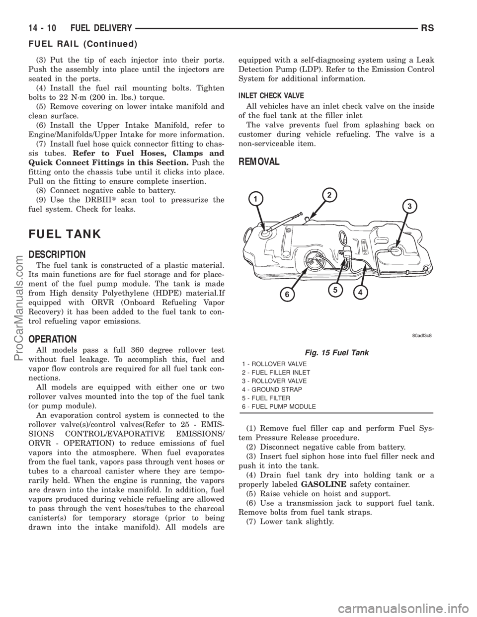
(1) Remove fuel filler cap and perform Fuel Sys-
tem Pressure Release procedure.
(2) Disconnect negative cable from battery.
(3) Insert fuel siphon hose into fuel filler neck and
push it into the tank.
(4) Drain fuel tank dry into holding tank or a
properly labeledGASOLINEsafety container.
(5) Raise vehicle on hoist and support.
(6) Use a transmission jack to support fuel tank.
Remove bolts from fuel tank straps.
(7) Lower tank slightly.
Fig. 15 Fuel Tank
1 - ROLLOVER VALVE
2 - FUEL FILLER INLET
3 - ROLLOVER VALVE
4 - GROUND STRAP
5 - FUEL FILTER
6 - FUEL PUMP MODULE
14 - 10 FUEL DELIVERYRS
FUEL RAIL (Continued)
ProCarManuals.com