2001 DODGE TOWN AND COUNTRY warning
[x] Cancel search: warningPage 1469 of 2321
WARNING: SAFETY GOGGLES SHOULD BE WORN
AT ALL TIMES WHEN WORKING ON STEERING
COLUMNS.
CAUTION: Disconnect negative (ground) cable from
the battery before servicing any column compo-
nent.
CAUTION: Do not attempt to remove the pivot pins
to disassemble the tilting mechanism. Damage will
occur.
DIAGNOSIS AND TESTING
For diagnosis of conditions relating to the steering
column (Refer to 19 - STEERING - DIAGNOSIS AND
TESTING) and (Refer to 19 - STEERING - DIAGNO-
SIS AND TESTING).
REMOVAL
To service the steering wheel components or the
airbag (Refer to 8 - ELECTRICAL/RESTRAINTS/
DRIVER AIRBAG - REMOVAL). Follow all WARN-
INGS AND CAUTIONS.
(1) Make sure the front wheels of the vehicle are
in the STRAIGHT AHEAD position before beginning
the column removal procedure.
(2) Disconnect negative (ground) cable from the
battery and isolate cable from battery terminal.
(3) Remove the lower shroud (Refer to 19 -
STEERING/COLUMN/LOWER SHROUD - REMOV-
AL).
(4) Remove the traction off switch.
(5) Remove the upper shroud.
(6) Remove the cluster trim bezel (Refer to 23 -
BODY/INSTRUMENT PANEL/CLUSTER BEZEL -
REMOVAL).(7) Remove the knee blocker (Refer to 23 - BODY/
INSTRUMENT PANEL/STEERING COLUMN
OPENING COVER - REMOVAL).
(8) Remove the parking brake handle link.
(9) Remove the knee blocker reinforcement (Refer
to 23 - BODY/INSTRUMENT PANEL/KNEE
BLOCKER - REMOVAL).
(10) Remove the airbag (Refer to 8 - ELECTRI-
CAL/RESTRAINTS/DRIVER AIRBAG - REMOVAL).
(11) Remove the steering wheel retaining nut.
(12) Remove the vibration damper weight.
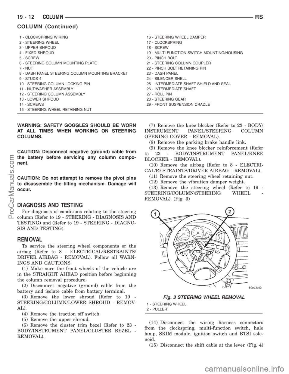
(13) Remove the steering wheel (Refer to 19 -
STEERING/COLUMN/STEERING WHEEL -
REMOVAL). (Fig. 3)
(14) Disconnect the wiring harness connectors
from the clockspring, multi-function switch, halo
lamp, SKIM module, ignition switch and BTSI sole-
noid.
(15) Disconnect the shift cable at the lever. (Fig. 4)
1 - CLOCKSPRING WIRING
2 - STEERING WHEEL
3 - UPPER SHROUD
4 - FIXED SHROUD
5 - SCREW
6 - STEERING COLUMN MOUNTING PLATE
7 - NUT
8 - DASH PANEL STEERING COLUMN MOUNTING BRACKET
9 - STUDS 4
10 - STEERING COLUMN LOCKING PIN
11 - NUT/WASHER ASSEMBLY
12 - STEERING COLUMN ASSEMBLY
13 - LOWER SHROUD
14 - SCREWS
15 - STEERING WHEEL RETAINING NUT16 - STEERING WHEEL DAMPER
17 - CLOCKSPRING
18 - SCREW
19 - MULTI-FUNCTION SWITCH MOUNTING/HOUSING
20 - PINCH BOLT
21 - STEERING COLUMN COUPLER
22 - PINCH BOLT RETAINING PIN
23 - DASH PANEL
24 - SILENCER SHELL
25 - INTERMEDIATE SHAFT SHIELD AND SEAL
26 - INTERMEDIATE SHAFT
27 - ROLL PIN
28 - STEERING GEAR
29 - FRONT SUSPENSION CRADLE
Fig. 3 STEERING WHEEL REMOVAL
1 - STEERING WHEEL
2 - PULLER
19 - 12 COLUMNRS
COLUMN (Continued)
ProCarManuals.com
Page 1475 of 2321
ing gear. This travel pushes and pulls the tie rods to
change the direction of the vehicle's front wheels.
Power assist steering provided by the power steer-
ing pump is controlled by an open center, rotary type
control valve which directs oil from the pump to
either side of the integral rack piston upon demand.
Road feel is controlled by the diameter of a torsion
bar which initially steers the vehicle. As required
steering effort increases, as in a turn, the torsion bar
twists, causing relative rotary motion between the
rotary valve body and the valve spool. This move-
ment directs oil behind the integral rack piston
which, in turn, builds up hydraulic pressure and
assists in the turning effort.
Manual steering control of the vehicle can be main-
tained if power steering assist is lost. However,
under this condition, steering effort is significantly
increased.
SERVICE WARNINGS AND CAUTIONS
WARNING: POWER STEERING FLUID, ENGINE
PARTS AND EXHAUST SYSTEM MAY BE
EXTREMELY HOT IF ENGINE HAS BEEN RUNNING.
DO NOT START ENGINE WITH ANY LOOSE OR DIS-
CONNECTED HOSES. DO NOT ALLOW HOSES TO
TOUCH HOT EXHAUST MANIFOLD OR CATALYST.
WARNING: FLUID LEVEL SHOULD BE CHECKED
WITH THE ENGINE OFF TO PREVENT PERSONAL
INJURY FROM MOVING PARTS.
CAUTION: When the system is open, cap all open
ends of the hoses, power steering pump fittings or
power steering gear ports to prevent entry of for-
eign material into the components.
REMOVAL - GEAR
CAUTION: Positioning the steering column in the
locked position will prevent the clockspring from
being accidentally over-extended when the steering
column is disconnected from the intermediate
steering coupler.
(1) Remove cap from power steering fluid reser-
voir.
(2) Using a siphon pump, remove as much fluid as
possible from the power steering fluid reservoir.
(3) With the ignition key in the locked position
turn the steering wheel to the left until the steering
wheel is in the locked position.
(4) With the vehicle on the ground, disconnect the
steering column shaft coupler from the steering gear
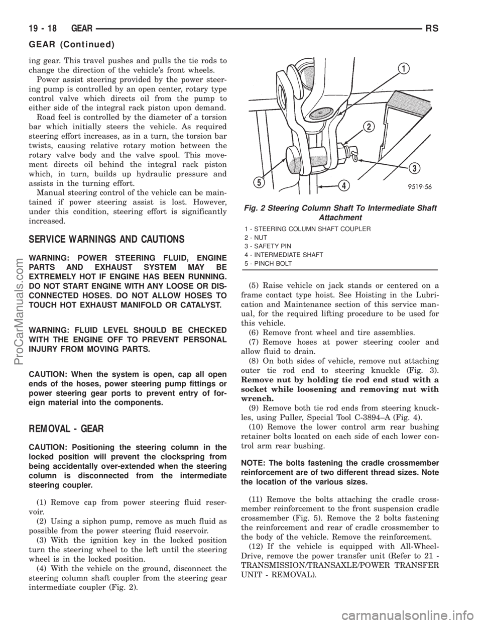
intermediate coupler (Fig. 2).(5) Raise vehicle on jack stands or centered on a
frame contact type hoist. See Hoisting in the Lubri-
cation and Maintenance section of this service man-
ual, for the required lifting procedure to be used for
this vehicle.
(6) Remove front wheel and tire assemblies.
(7) Remove hoses at power steering cooler and
allow fluid to drain.
(8) On both sides of vehicle, remove nut attaching
outer tie rod end to steering knuckle (Fig. 3).
Remove nut by holding tie rod end stud with a
socket while loosening and removing nut with
wrench.
(9) Remove both tie rod ends from steering knuck-
les, using Puller, Special Tool C-3894±A (Fig. 4).
(10) Remove the lower control arm rear bushing
retainer bolts located on each side of each lower con-
trol arm rear bushing.
NOTE: The bolts fastening the cradle crossmember
reinforcement are of two different thread sizes. Note
the location of the various sizes.
(11) Remove the bolts attaching the cradle cross-
member reinforcement to the front suspension cradle
crossmember (Fig. 5). Remove the 2 bolts fastening
the reinforcement and rear of cradle crossmember to
the body of the vehicle. Remove the reinforcement.
(12) If the vehicle is equipped with All-Wheel-
Drive, remove the power transfer unit (Refer to 21 -
TRANSMISSION/TRANSAXLE/POWER TRANSFER
UNIT - REMOVAL).
Fig. 2 Steering Column Shaft To Intermediate Shaft
Attachment
1 - STEERING COLUMN SHAFT COUPLER
2 - NUT
3 - SAFETY PIN
4 - INTERMEDIATE SHAFT
5 - PINCH BOLT
19 - 18 GEARRS
GEAR (Continued)
ProCarManuals.com
Page 1482 of 2321
SERVICE WARNINGS AND CAUTIONS
WARNING: POWER STEERING FLUID, ENGINE
PARTS AND EXHAUST SYSTEM MAY BE
EXTREMELY HOT IF ENGINE HAS BEEN RUNNING.
DO NOT START ENGINE WITH ANY LOOSE OR DIS-
CONNECTED HOSES. DO NOT ALLOW HOSES TO
TOUCH HOT EXHAUST MANIFOLD OR CATALYST.
WARNING: FLUID LEVEL SHOULD BE CHECKED
WITH THE ENGINE OFF TO PREVENT PERSONAL
INJURY FROM MOVING PARTS.
CAUTION: When the system is open, cap all open
ends of the hoses, power steering pump fittings or
power steering gear ports to prevent entry of for-
eign material into the components.
STANDARD PROCEDURE - POWER STEERING
PUMP INITIAL OPERATION
CAUTION: The fluid level should be checked with
engine off to prevent injury from moving compo-
nents. Use only MoparTPower Steering Fluid (MS-
5931) or approved equivalent. Do not overfill.
Read the fluid level through the side of the power
steering fluid reservoir. The fluid level should indi-
cateªFILL RANGEºwhen the fluid is at a temper-
ature of approximately 21ÉC to 27ÉC (70ÉF to 80ÉF).
(1) Wipe the filler cap and area clean, then remove
the cap.
(2) Fill the fluid reservoir to the proper level and
let the fluid settle for at least two (2) minutes.
(3) Start the engine and let run for a few seconds,
then turn the engine off.
(4) Add fluid if necessary. Repeat the above steps
until the fluid level remains constant after running
the engine.
(5) Raise the front wheels off the ground.
(6) Start the engine.
(7) Slowly turn the steering wheel right and left,
lightly contacting the wheel stops.
(8) Add fluid if necessary.
(9) Lower the vehicle, then turn the steering wheel
slowly from lock-to-lock.
(10) Stop the engine. Check the fluid level and
refill as required.
(11) If the fluid is extremely foamy, allow the vehi-
cle to stabilize a few minutes, then repeat the above
procedure.
REMOVAL - PUMP (2.4L ENGINE)
(1) Remove the (-) negative battery cable from the
battery and isolate cable.
(2) Remove the cap from the power steering fluid
reservoir.
(3) Using a siphon pump, remove as much power
steering fluid as possible from the power steering
fluid reservoir.
(4) Raise the vehicle on jack stands or centered on
a frame contact type hoist. See Hoisting in Lubrica-
tion and Maintenance.
(5) Disconnect the oxygen sensor wiring harness
from the vehicle wiring harness at the rear engine
mount bracket.
NOTE: The exhaust system needs to be removed
from the engine to allow for an area to remove the
power steering pump from the vehicle.
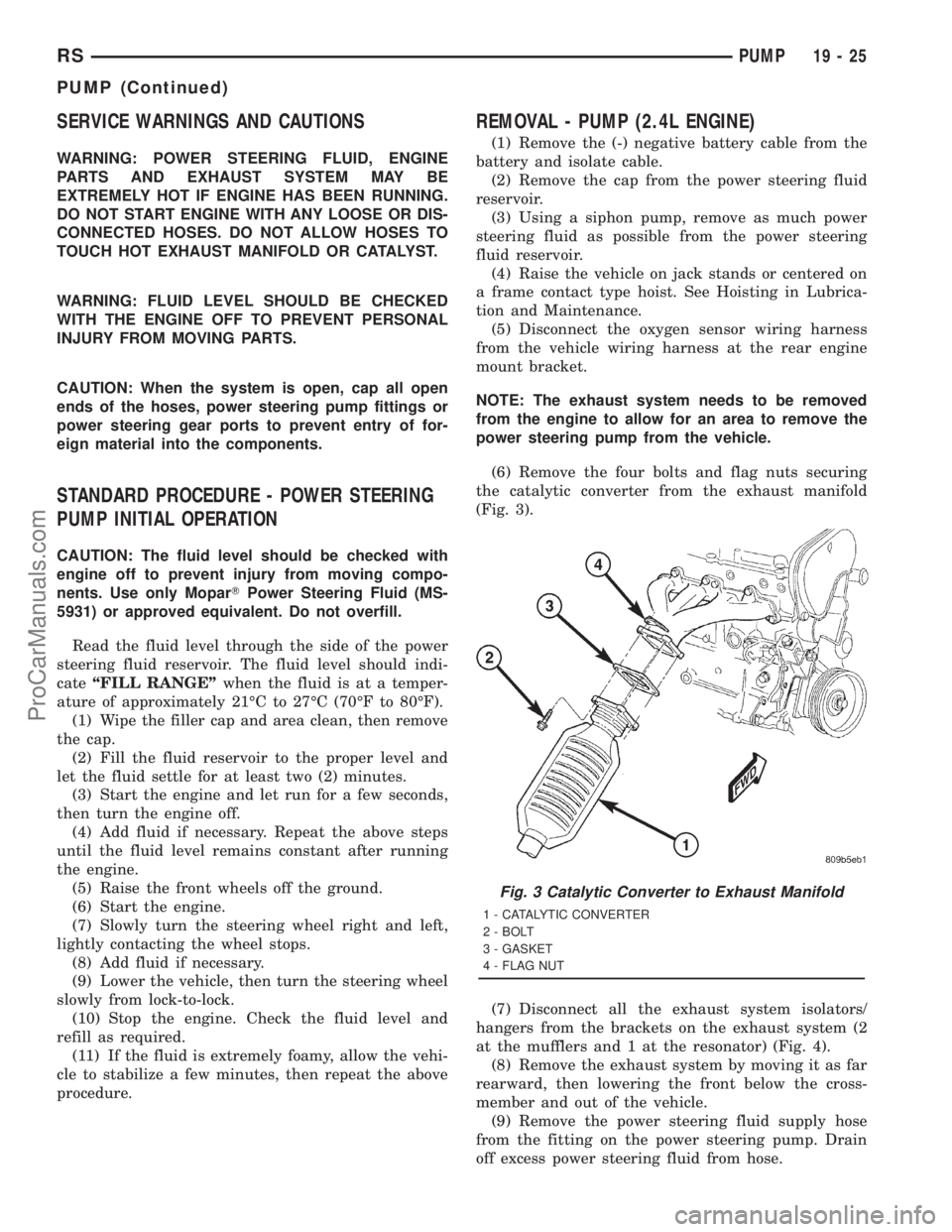
(6) Remove the four bolts and flag nuts securing
the catalytic converter from the exhaust manifold
(Fig. 3).
(7) Disconnect all the exhaust system isolators/
hangers from the brackets on the exhaust system (2
at the mufflers and 1 at the resonator) (Fig. 4).
(8) Remove the exhaust system by moving it as far
rearward, then lowering the front below the cross-
member and out of the vehicle.
(9) Remove the power steering fluid supply hose
from the fitting on the power steering pump. Drain
off excess power steering fluid from hose.
Fig. 3 Catalytic Converter to Exhaust Manifold
1 - CATALYTIC CONVERTER
2 - BOLT
3 - GASKET
4 - FLAG NUT
RSPUMP19-25
PUMP (Continued)
ProCarManuals.com
Page 1487 of 2321
(4) Install the power steering fluid pressure line
into the pressure output fitting of the power steering
pump (Fig. 11). Tighten the pressure line to pump fit-
ting tube nut to a torque of 31 N´m (275 in. lbs.).
(5) Install the power steering fluid low-pressure
return hose on the power steering pump low pressure
fitting (Fig. 11).Be sure hose clamps are prop-
erly reinstalled.
(6) Raise the vehicle.
(7) Install the routing clip on the engine for the
pressure hose (Fig. 10).
(8) Tighten the pump thru-bolt (Fig. 9). Tighten to
54 N´m (40 ft. lbs.) torque.
(9) Install the serpentine drive belt (Refer to 7 -
COOLING/ACCESSORY DRIVE/DRIVE BELTS -
INSTALLATION).
(10) Install the drive belt splash shield.
(11) Lower the vehicle.
(12) Install the wiper module (unit)(Refer to 8 -
ELECTRICAL/WIPERS/WASHERS/WIPER MOD-
ULE - INSTALLATION).
(13) Connect the negative battery cable on the
negative battery post.
(14) Fill and bleed the power steering system
using the Power Steering Pump Initial Operation
Procedure (Refer to 19 - STEERING/PUMP - STAN-
DARD PROCEDURE).
(15) Inspect for leaks.
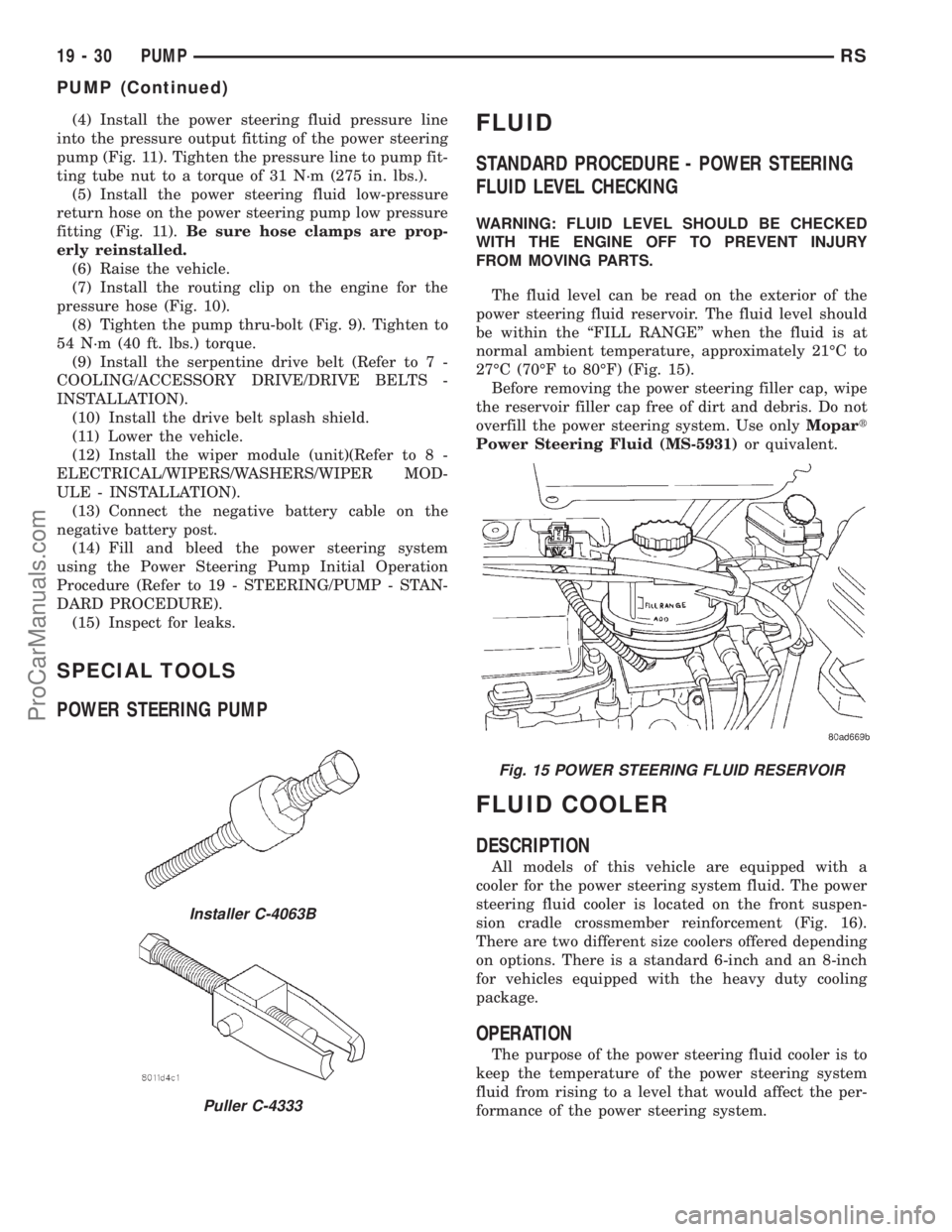
SPECIAL TOOLS
POWER STEERING PUMP
FLUID
STANDARD PROCEDURE - POWER STEERING
FLUID LEVEL CHECKING
WARNING: FLUID LEVEL SHOULD BE CHECKED
WITH THE ENGINE OFF TO PREVENT INJURY
FROM MOVING PARTS.
The fluid level can be read on the exterior of the
power steering fluid reservoir. The fluid level should
be within the ªFILL RANGEº when the fluid is at
normal ambient temperature, approximately 21ÉC to
27ÉC (70ÉF to 80ÉF) (Fig. 15).
Before removing the power steering filler cap, wipe
the reservoir filler cap free of dirt and debris. Do not
overfill the power steering system. Use onlyMopart
Power Steering Fluid (MS-5931)or quivalent.
FLUID COOLER
DESCRIPTION
All models of this vehicle are equipped with a
cooler for the power steering system fluid. The power
steering fluid cooler is located on the front suspen-
sion cradle crossmember reinforcement (Fig. 16).
There are two different size coolers offered depending
on options. There is a standard 6-inch and an 8-inch
for vehicles equipped with the heavy duty cooling
package.
OPERATION
The purpose of the power steering fluid cooler is to
keep the temperature of the power steering system
fluid from rising to a level that would affect the per-
formance of the power steering system.
Installer C-4063B
Puller C-4333
Fig. 15 POWER STEERING FLUID RESERVOIR
19 - 30 PUMPRS
PUMP (Continued)
ProCarManuals.com
Page 1588 of 2321
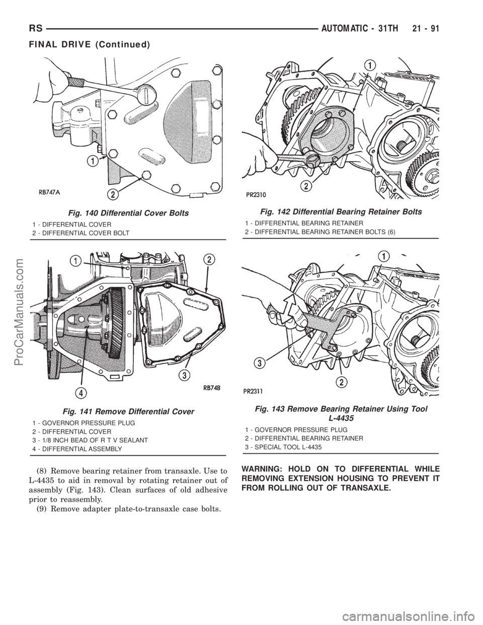
(8) Remove bearing retainer from transaxle. Use to
L-4435 to aid in removal by rotating retainer out of
assembly (Fig. 143). Clean surfaces of old adhesive
prior to reassembly.
(9) Remove adapter plate-to-transaxle case bolts.WARNING: HOLD ON TO DIFFERENTIAL WHILE
REMOVING EXTENSION HOUSING TO PREVENT IT
FROM ROLLING OUT OF TRANSAXLE.
Fig. 140 Differential Cover Bolts
1 - DIFFERENTIAL COVER
2 - DIFFERENTIAL COVER BOLT
Fig. 141 Remove Differential Cover
1 - GOVERNOR PRESSURE PLUG
2 - DIFFERENTIAL COVER
3 - 1/8 INCH BEAD OF R T V SEALANT
4 - DIFFERENTIAL ASSEMBLY
Fig. 142 Differential Bearing Retainer Bolts
1 - DIFFERENTIAL BEARING RETAINER
2 - DIFFERENTIAL BEARING RETAINER BOLTS (6)
Fig. 143 Remove Bearing Retainer Using Tool
L-4435
1 - GOVERNOR PRESSURE PLUG
2 - DIFFERENTIAL BEARING RETAINER
3 - SPECIAL TOOL L-4435
RSAUTOMATIC - 31TH21-91
FINAL DRIVE (Continued)
ProCarManuals.com
Page 1732 of 2321
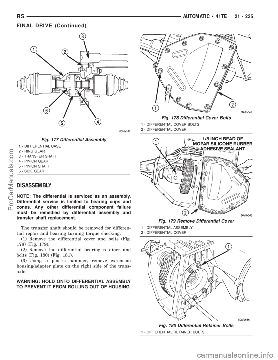
DISASSEMBLY
NOTE: The differential is serviced as an assembly.
Differential service is limited to bearing cups and
cones. Any other differential component failure
must be remedied by differential assembly and
transfer shaft replacement.
The transfer shaft should be removed for differen-
tial repair and bearing turning torque checking.
(1) Remove the differential cover and bolts (Fig.
178) (Fig. 179).
(2) Remove the differential bearing retainer and
bolts (Fig. 180) (Fig. 181).
(3) Using a plastic hammer, remove extension
housing/adapter plate on the right side of the trans-
axle.
WARNING: HOLD ONTO DIFFERENTIAL ASSEMBLY
TO PREVENT IT FROM ROLLING OUT OF HOUSING.
Fig. 177 Differential Assembly
1 - DIFFERENTIAL CASE
2 - RING GEAR
3 - TRANSFER SHAFT
4 - PINION GEAR
5 - PINION SHAFT
6 - SIDE GEAR
Fig. 178 Differential Cover Bolts
1 - DIFFERENTIAL COVER BOLTS
2 - DIFFERENTIAL COVER
Fig. 179 Remove Differential Cover
1 - DIFFERENTIAL ASSEMBLY
2 - DIFFERENTIAL COVER
Fig. 180 Differential Retainer Bolts
1 - DIFFERENTIAL RETAINER BOLTS
RSAUTOMATIC - 41TE21 - 235
FINAL DRIVE (Continued)
ProCarManuals.com
Page 1904 of 2321
Performance tires will have a speed rating letter
after the aspect ratio number. For example, the letter
ªSº indicates that the tire is speed rated up to 112
mph (180 km/h). The speed rating is not always
printed on the tire sidewall.
²Q -up to 100 mph (160 km/h)
²S -up to 112 mph (180 km/h)
²T -up to 118 mph (190 km/h)
²U -up to 124 mph (200 km/h)
²H -up to 130 mph (210 km/h)
²V -up to 149 mph (240 km/h)
²Z -more than 149 mph (240 km/h) (consult the
tire manufacturer for the specific speed rating)
An All Season type tire will have eitherM+S,M
& S or M-S (indicating mud and snow traction)
imprinted on the side wall.
TIRE CHAINS
Refer to the owners manual supplied with the vehi-
cle to determine whether the use of tire chains is per-
mitted on this vehicle.
DESCRIPTION - RADIAL-PLY TIRES
Radial-ply tires improve handling, tread life, ride
quality and decrease rolling resistance.
Radial-ply tires must always be used in sets of four
and under no circumstances should they be used on
the front only. It is recommended that tires from dif-
ferent manufacturers NOT be mixed. They may bemixed with a temporary spare tire when necessary. A
maximum speed of 80 km/h (50 mph) is recom-
mended while a temporary spare is in use.
Radial-ply tires have the same load-carrying capac-
ity as other types of tires of the same size. They also
use the same recommended inflation pressures.
DESCRIPTION - REPLACEMENT TIRES
WARNING: FAILURE TO EQUIP THE VEHICLE WITH
TIRES HAVING ADEQUATE SPEED CAPABILITY
CAN RESULT IN SUDDEN TIRE FAILURE.
It is recommended that tires equivalent to the orig-
inal equipment tires be used when replacement is
needed.
Failure to use equivalent replacement tires may
adversely affect the safety and handling of the vehicle.
The original equipment tires provide a proper com-
bination of many characteristics such as:
²Ride
²Noise
²Handling
²Durability
²Tread life
²Traction
²Rolling resistance
²Speed capability
The use of oversize tires may cause interference
with vehicle components. Under extremes of suspen-
sion and steering travel, interference with vehicle
components may cause tire damage.
DESCRIPTION - SPARE TIRE (TEMPORARY)
The temporary (convenience) spare tire is designed
for emergency use only. The original tire should be
repaired and reinstalled, or replaced with a new, at
the first opportunity.
The temporary (convenience) spare tire should be
inflated to the pressure listed on its sidewall. Do not
exceed speeds of 80 km/h (50 mph) when the tempo-
rary spare tire is in use on the vehicle. Refer to the
Owner's Manual for more details.
DIAGNOSIS AND TESTING - TIRE NOISE
Unusual tire noise can be associated with tire and
wheel vibration or irregular tire wear. For vibration,
(Refer to 22 - TIRES/WHEELS - DIAGNOSIS AND
TESTING). For irregular tire wear, (Refer to 22 - TIRES/
WHEELS/TIRES - DIAGNOSIS AND TESTING).
DIAGNOSIS AND TESTING - TIRE/VEHICLE
LEAD
Use the following Vehicle Lead Diagnosis And Cor-
rection Chart to diagnose and correct a vehicle lead
or drift problem.
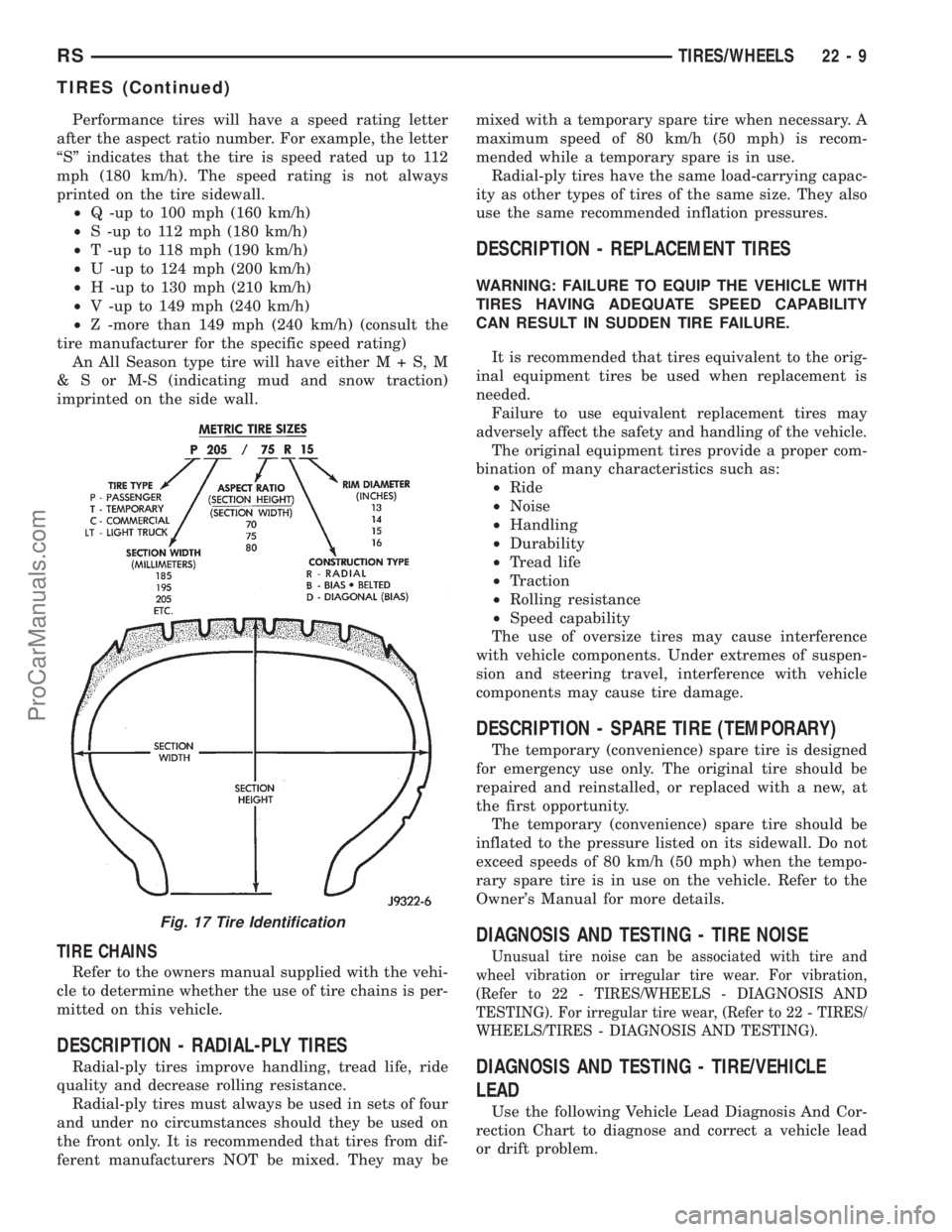
Fig. 17 Tire Identification
RSTIRES/WHEELS22-9
TIRES (Continued)
ProCarManuals.com
Page 1907 of 2321
Improper inflation can cause:
²Uneven wear patterns
²Reduced tread life
²Reduced fuel economy
²Unsatisfactory ride
²The vehicle to drift.
WARNING: OVER OR UNDER INFLATED TIRES CAN
AFFECT VEHICLE HANDLING. THE TIRE CAN FAIL
SUDDENLY, RESULTING IN LOSS OF VEHICLE
CONTROL.
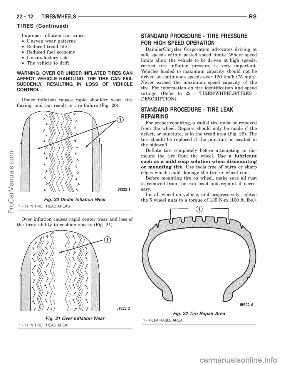
Under inflation causes rapid shoulder wear, tire
flexing, and can result in tire failure (Fig. 20).
Over inflation causes rapid center wear and loss of
the tire's ability to cushion shocks (Fig. 21).STANDARD PROCEDURE - TIRE PRESSURE
FOR HIGH SPEED OPERATION
DaimlerChrysler Corporation advocates driving at
safe speeds within posted speed limits. Where speed
limits allow the vehicle to be driven at high speeds,
correct tire inflation pressure is very important.
Vehicles loaded to maximum capacity should not be
driven at continuous speeds over 120 km/h (75 mph).
Never exceed the maximum speed capacity of the
tire. For information on tire identification and speed
ratings, (Refer to 22 - TIRES/WHEELS/TIRES -
DESCRIPTION).
STANDARD PROCEDURE - TIRE LEAK
REPAIRING
For proper repairing, a radial tire must be removed
from the wheel. Repairs should only be made if the
defect, or puncture, is in the tread area (Fig. 22). The
tire should be replaced if the puncture is located in
the sidewall.
Deflate tire completely before attempting to dis-
mount the tire from the wheel.Use a lubricant
such as a mild soap solution when dismounting
or mounting tire.Use tools free of burrs or sharp
edges which could damage the tire or wheel rim.
Before mounting tire on wheel, make sure all rust
is removed from the rim bead and repaint if neces-
sary.
Install wheel on vehicle, and progressively tighten
the 5 wheel nuts to a torque of 135 N´m (100 ft. lbs.).
Fig. 20 Under Inflation Wear
1 - THIN TIRE TREAD AREAS
Fig. 21 Over Inflation Wear
1 - THIN TIRE TREAD AREA
Fig. 22 Tire Repair Area
1 - REPAIRABLE AREA
22 - 12 TIRES/WHEELSRS
TIRES (Continued)
ProCarManuals.com