2001 DODGE TOWN AND COUNTRY warning
[x] Cancel search: warningPage 1414 of 2321
FUEL RAIL
REMOVAL - 2.4L
(1) Perform fuel system pressure release procedure
before servicing or starting repairs.Refer to
Fuel System Pressure Release Procedure in this sec-
tion.
(2) Disconnect negative cable from battery.
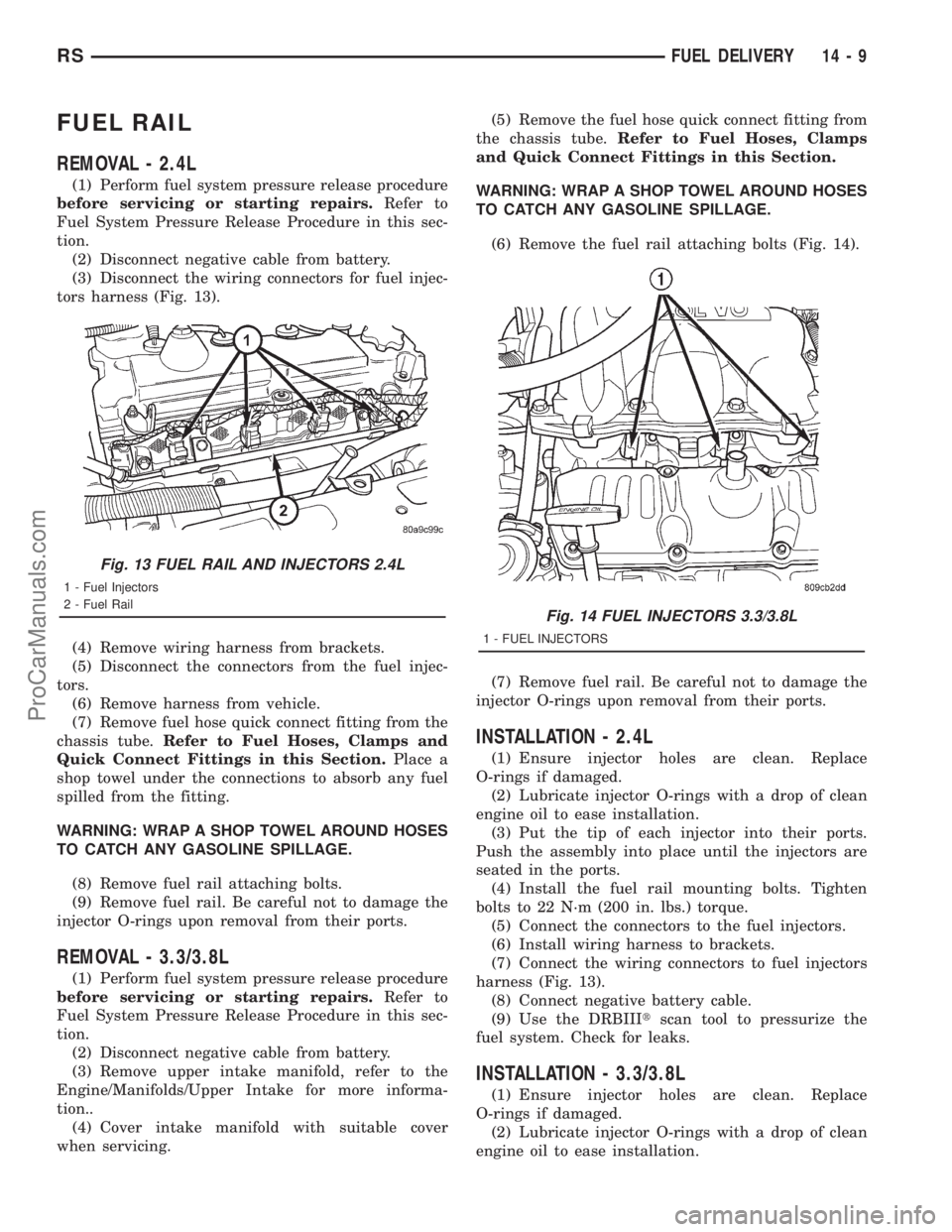
(3) Disconnect the wiring connectors for fuel injec-
tors harness (Fig. 13).
(4) Remove wiring harness from brackets.
(5) Disconnect the connectors from the fuel injec-
tors.
(6) Remove harness from vehicle.
(7) Remove fuel hose quick connect fitting from the
chassis tube.Refer to Fuel Hoses, Clamps and
Quick Connect Fittings in this Section.Place a
shop towel under the connections to absorb any fuel
spilled from the fitting.
WARNING: WRAP A SHOP TOWEL AROUND HOSES
TO CATCH ANY GASOLINE SPILLAGE.
(8) Remove fuel rail attaching bolts.
(9) Remove fuel rail. Be careful not to damage the
injector O-rings upon removal from their ports.
REMOVAL - 3.3/3.8L
(1) Perform fuel system pressure release procedure
before servicing or starting repairs.Refer to
Fuel System Pressure Release Procedure in this sec-
tion.
(2) Disconnect negative cable from battery.
(3) Remove upper intake manifold, refer to the
Engine/Manifolds/Upper Intake for more informa-
tion..
(4) Cover intake manifold with suitable cover
when servicing.(5) Remove the fuel hose quick connect fitting from
the chassis tube.Refer to Fuel Hoses, Clamps
and Quick Connect Fittings in this Section.
WARNING: WRAP A SHOP TOWEL AROUND HOSES
TO CATCH ANY GASOLINE SPILLAGE.
(6) Remove the fuel rail attaching bolts (Fig. 14).
(7) Remove fuel rail. Be careful not to damage the
injector O-rings upon removal from their ports.
INSTALLATION - 2.4L
(1) Ensure injector holes are clean. Replace
O-rings if damaged.
(2) Lubricate injector O-rings with a drop of clean
engine oil to ease installation.
(3) Put the tip of each injector into their ports.
Push the assembly into place until the injectors are
seated in the ports.
(4) Install the fuel rail mounting bolts. Tighten
bolts to 22 N´m (200 in. lbs.) torque.
(5) Connect the connectors to the fuel injectors.
(6) Install wiring harness to brackets.
(7) Connect the wiring connectors to fuel injectors
harness (Fig. 13).
(8) Connect negative battery cable.
(9) Use the DRBIIItscan tool to pressurize the
fuel system. Check for leaks.
INSTALLATION - 3.3/3.8L
(1) Ensure injector holes are clean. Replace
O-rings if damaged.
(2) Lubricate injector O-rings with a drop of clean
engine oil to ease installation.
Fig. 13 FUEL RAIL AND INJECTORS 2.4L
1 - Fuel Injectors
2 - Fuel Rail
Fig. 14 FUEL INJECTORS 3.3/3.8L
1 - FUEL INJECTORS
RSFUEL DELIVERY14-9
ProCarManuals.com
Page 1418 of 2321
INLET FILTER
REMOVAL
(1) Remove fuel pump module. Refer to Fuel Pump
Module Removal in this section.
(2) Using a thin straight blade screwdriver, pry
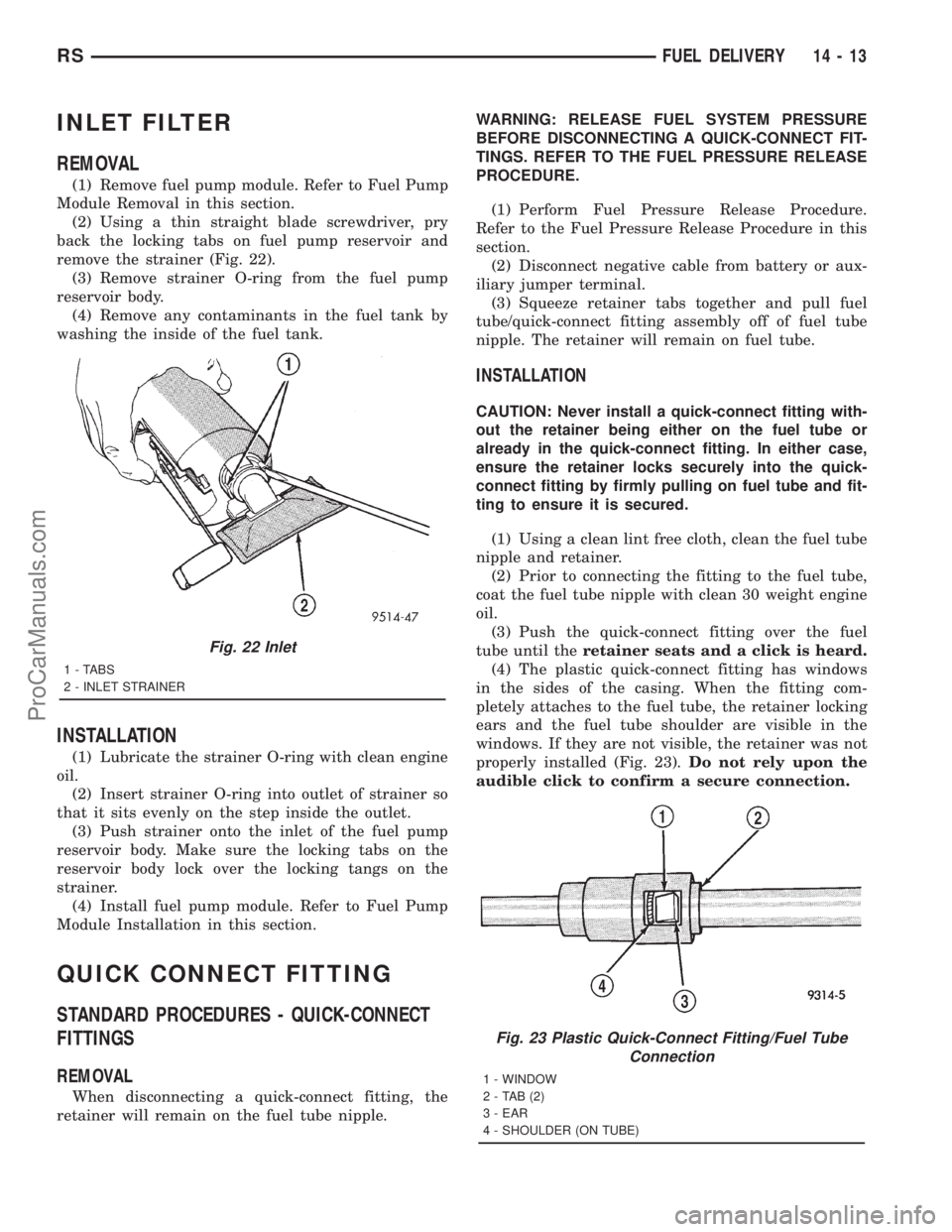
back the locking tabs on fuel pump reservoir and
remove the strainer (Fig. 22).
(3) Remove strainer O-ring from the fuel pump
reservoir body.
(4) Remove any contaminants in the fuel tank by
washing the inside of the fuel tank.
INSTALLATION
(1) Lubricate the strainer O-ring with clean engine
oil.
(2) Insert strainer O-ring into outlet of strainer so
that it sits evenly on the step inside the outlet.
(3) Push strainer onto the inlet of the fuel pump
reservoir body. Make sure the locking tabs on the
reservoir body lock over the locking tangs on the
strainer.
(4) Install fuel pump module. Refer to Fuel Pump
Module Installation in this section.
QUICK CONNECT FITTING
STANDARD PROCEDURES - QUICK-CONNECT
FITTINGS
REMOVAL
When disconnecting a quick-connect fitting, the
retainer will remain on the fuel tube nipple.WARNING: RELEASE FUEL SYSTEM PRESSURE
BEFORE DISCONNECTING A QUICK-CONNECT FIT-
TINGS. REFER TO THE FUEL PRESSURE RELEASE
PROCEDURE.
(1) Perform Fuel Pressure Release Procedure.
Refer to the Fuel Pressure Release Procedure in this
section.
(2) Disconnect negative cable from battery or aux-
iliary jumper terminal.
(3) Squeeze retainer tabs together and pull fuel
tube/quick-connect fitting assembly off of fuel tube
nipple. The retainer will remain on fuel tube.
INSTALLATION
CAUTION: Never install a quick-connect fitting with-
out the retainer being either on the fuel tube or
already in the quick-connect fitting. In either case,
ensure the retainer locks securely into the quick-
connect fitting by firmly pulling on fuel tube and fit-
ting to ensure it is secured.
(1) Using a clean lint free cloth, clean the fuel tube
nipple and retainer.
(2) Prior to connecting the fitting to the fuel tube,
coat the fuel tube nipple with clean 30 weight engine
oil.
(3) Push the quick-connect fitting over the fuel
tube until theretainer seats and a click is heard.
(4) The plastic quick-connect fitting has windows
in the sides of the casing. When the fitting com-
pletely attaches to the fuel tube, the retainer locking
ears and the fuel tube shoulder are visible in the
windows. If they are not visible, the retainer was not
properly installed (Fig. 23).Do not rely upon the
audible click to confirm a secure connection.
Fig. 22 Inlet
1 - TABS
2 - INLET STRAINER
Fig. 23 Plastic Quick-Connect Fitting/Fuel Tube
Connection
1 - WINDOW
2-TAB(2)
3 - EAR
4 - SHOULDER (ON TUBE)
RSFUEL DELIVERY14-13
ProCarManuals.com
Page 1419 of 2321
(5) Connect negative cable to battery or auxiliary
jumper terminal.
CAUTION: When using the ASD Fuel System Test,
the Auto Shutdown (ASD) Relay remains energized
for several minutes, until the test is stopped, or
until the ignition switch is turned to the Off posi-
tion.
(6) Use the DRB IIItscan tool ASD Fuel System
Test to pressurize the fuel system. Check for leaks.
TWO-TAB TYPE FITTING
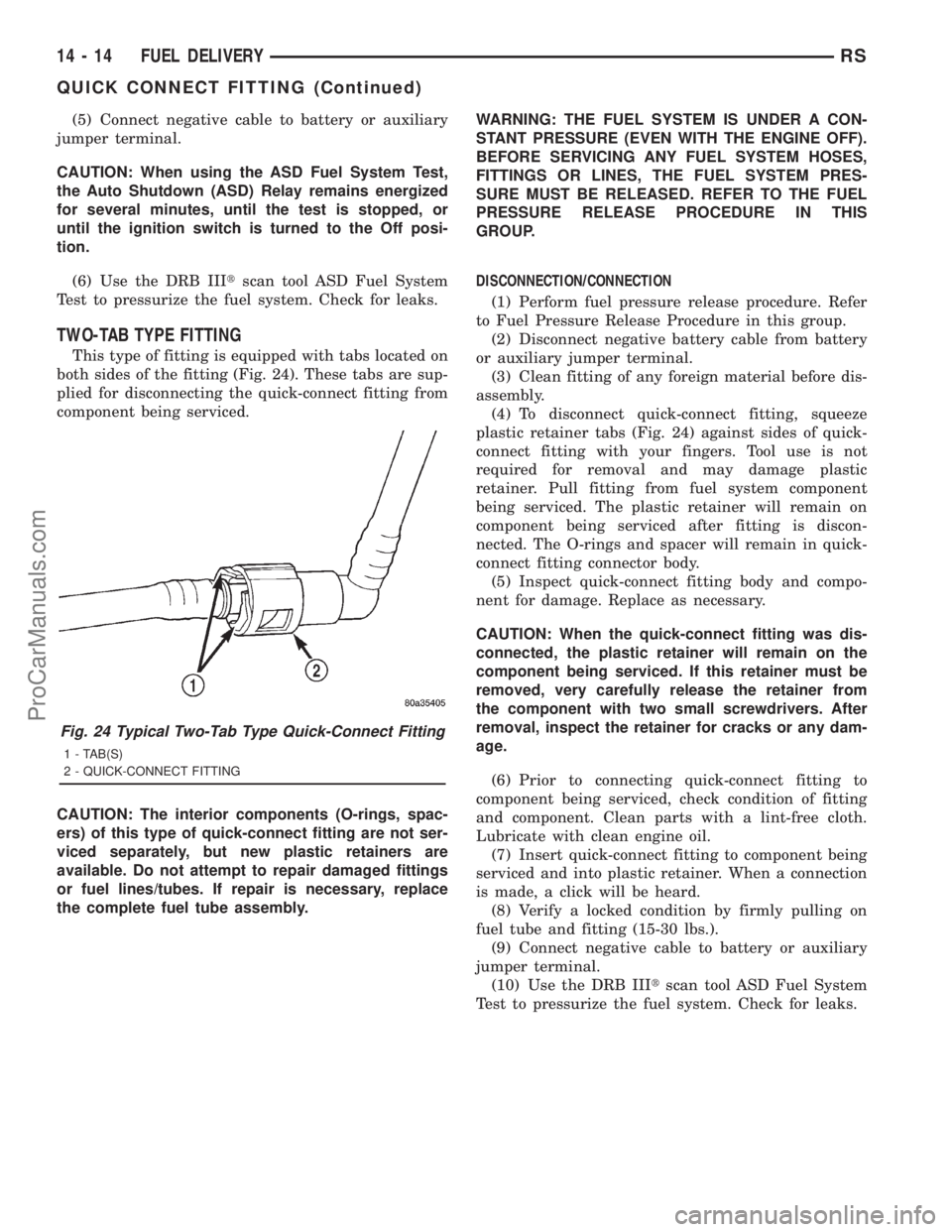
This type of fitting is equipped with tabs located on
both sides of the fitting (Fig. 24). These tabs are sup-
plied for disconnecting the quick-connect fitting from
component being serviced.
CAUTION: The interior components (O-rings, spac-
ers) of this type of quick-connect fitting are not ser-
viced separately, but new plastic retainers are
available. Do not attempt to repair damaged fittings
or fuel lines/tubes. If repair is necessary, replace
the complete fuel tube assembly.WARNING: THE FUEL SYSTEM IS UNDER A CON-
STANT PRESSURE (EVEN WITH THE ENGINE OFF).
BEFORE SERVICING ANY FUEL SYSTEM HOSES,
FITTINGS OR LINES, THE FUEL SYSTEM PRES-
SURE MUST BE RELEASED. REFER TO THE FUEL
PRESSURE RELEASE PROCEDURE IN THIS
GROUP.
DISCONNECTION/CONNECTION
(1) Perform fuel pressure release procedure. Refer
to Fuel Pressure Release Procedure in this group.
(2) Disconnect negative battery cable from battery
or auxiliary jumper terminal.
(3) Clean fitting of any foreign material before dis-
assembly.
(4) To disconnect quick-connect fitting, squeeze
plastic retainer tabs (Fig. 24) against sides of quick-
connect fitting with your fingers. Tool use is not
required for removal and may damage plastic
retainer. Pull fitting from fuel system component
being serviced. The plastic retainer will remain on
component being serviced after fitting is discon-
nected. The O-rings and spacer will remain in quick-
connect fitting connector body.
(5) Inspect quick-connect fitting body and compo-
nent for damage. Replace as necessary.
CAUTION: When the quick-connect fitting was dis-
connected, the plastic retainer will remain on the
component being serviced. If this retainer must be
removed, very carefully release the retainer from
the component with two small screwdrivers. After
removal, inspect the retainer for cracks or any dam-
age.
(6) Prior to connecting quick-connect fitting to
component being serviced, check condition of fitting
and component. Clean parts with a lint-free cloth.
Lubricate with clean engine oil.
(7) Insert quick-connect fitting to component being
serviced and into plastic retainer. When a connection
is made, a click will be heard.
(8) Verify a locked condition by firmly pulling on
fuel tube and fitting (15-30 lbs.).
(9) Connect negative cable to battery or auxiliary
jumper terminal.
(10) Use the DRB IIItscan tool ASD Fuel System
Test to pressurize the fuel system. Check for leaks.
Fig. 24 Typical Two-Tab Type Quick-Connect Fitting
1 - TAB(S)
2 - QUICK-CONNECT FITTING
14 - 14 FUEL DELIVERYRS
QUICK CONNECT FITTING (Continued)
ProCarManuals.com
Page 1420 of 2321
PLASTIC RETAINER RING TYPE FITTING
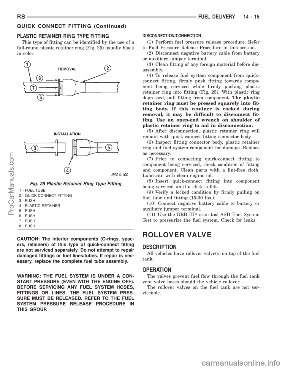
This type of fitting can be identified by the use of a
full-round plastic retainer ring (Fig. 25) usually black
in color.
CAUTION: The interior components (O-rings, spac-
ers, retainers) of this type of quick-connect fitting
are not serviced separately. Do not attempt to repair
damaged fittings or fuel lines/tubes. If repair is nec-
essary, replace the complete fuel tube assembly.
WARNING: THE FUEL SYSTEM IS UNDER A CON-
STANT PRESSURE (EVEN WITH THE ENGINE OFF).
BEFORE SERVICING ANY FUEL SYSTEM HOSES,
FITTINGS OR LINES, THE FUEL SYSTEM PRES-
SURE MUST BE RELEASED. REFER TO THE FUEL
SYSTEM PRESSURE RELEASE PROCEDURE IN
THIS GROUP.DISCONNECTION/CONNECTION
(1) Perform fuel pressure release procedure. Refer
to Fuel Pressure Release Procedure in this section.
(2) Disconnect negative battery cable from battery
or auxiliary jumper terminal.
(3) Clean fitting of any foreign material before dis-
assembly.
(4) To release fuel system component from quick-
connect fitting, firmly push fitting towards compo-
nent being serviced while firmly pushing plastic
retainer ring into fitting (Fig. 25). With plastic ring
depressed, pull fitting from component.The plastic
retainer ring must be pressed squarely into fit-
ting body. If this retainer is cocked during
removal, it may be difficult to disconnect fit-
ting. Use an open-end wrench on shoulder of
plastic retainer ring to aid in disconnection.
(5) After disconnection, plastic retainer ring will
remain with quick-connect fitting connector body.
(6) Inspect fitting connector body, plastic retainer
ring and fuel system component for damage. Replace
as necessary.
(7) Prior to connecting quick-connect fitting to
component being serviced, check condition of fitting
and component. Clean parts with a lint-free cloth.
Lubricate with clean engine oil.
(8) Insert quick-connect fitting into component
being serviced until a click is felt.
(9) Verify a locked condition by firmly pulling on
fuel tube and fitting (15-30 lbs.).
(10) Connect negative battery cable to battery or
auxiliary jumper terminal.
(11) Use the DRB IIItscan tool ASD Fuel System
Test to pressurize the fuel system. Check for leaks.
ROLLOVER VALVE
DESCRIPTION
All vehicles have rollover valve(s) on top of the fuel
tank.
OPERATION
The valves prevent fuel flow through the fuel tank
vent valve hoses should the vehicle rollover.
The rollover valves on the fuel tank are not ser-
viceable.
Fig. 25 Plastic Retainer Ring Type Fitting
1 - FUEL TUBE
2 - QUICK CONNECT FITTING
3 - PUSH
4 - PLASTIC RETAINER
5 - PUSH
6 - PUSH
7 - PUSH
8 - PUSH
RSFUEL DELIVERY14-15
QUICK CONNECT FITTING (Continued)
ProCarManuals.com
Page 1442 of 2321
FUEL SYSTEM
TABLE OF CONTENTS
page page
FUEL SYSTEM 2.5L TURBO DIESEL
DESCRIPTION............................1
WARNING...............................1
DIAGNOSIS AND TESTING..................1
AIR IN FUEL SYSTEM....................1
FUEL SUPPLY RESTRICTIONS.............1STANDARD PROCEDURE...................2
WATER DRAINING AT FUEL FILTER.........2
CLEANING FUEL SYSTEM PARTS...........2
SPECIFICATIONS.........................2
FUEL DELIVERY..........................3
FUEL INJECTION........................10
FUEL SYSTEM 2.5L TURBO
DIESEL
DESCRIPTION - DIESEL FUEL DELIVERY
SYSTEM
The fuel system on the 2.5L Common Rail Diesel
Engine uses a fuel injection pump and an Electronic
Control Module (ECM).
The fuel delivery system consists of the:
²Accelerator pedal
²Air cleaner housing/element
²Fuel filter/water separator
²Fuel heater
²Fuel heater relay
²Fuel transfer (lift) pump
²Fuel injection pump
²Fuel injectors
²Fuel tank
²Fuel tank filler/vent tube assembly
²Fuel tank filler tube cap
²Fuel tank module containing the rollover valve
and a fuel gauge sending unit (fuel level sensor).
²Fuel tubes/lines/hoses
²High-pressure fuel injector lines
²Low-pressure fuel supply lines
²Low-pressure fuel return line
²Overflow valve
²Quick-connect fittings
²Water draining
WARNING - HIGH FUEL SYSTEM PRESSURE
WARNING: THE INJECTION PUMP SUPPLIES HIGH-
PRESSURE FUEL TO EACH INDIVIDUAL INJECTOR
THROUGH HIGH-PRESSURE LINES. FUEL UNDER
THIS AMOUNT OF PRESSURE CAN PENETRATE
SKIN AND CAUSE PERSONAL INJURY. WEAR
SAFETY GOGGLES AND ADEQUATE PROTECTIVE
CLOTHING. AVOID CONTACT WITH FUEL SPRAY
WHEN BLEEDING HIGH-PRESSURE FUEL LINES.
DIAGNOSIS AND TESTING - AIR IN FUEL
SYSTEM
Air will enter the fuel system whenever fuel supply
lines, separator filters, injection pump, high-pressure
lines or injectors are removed or disconnected. Air
trapped in the fuel system can result in hard start-
ing, a rough running engine, engine misfire, low
power, excessive smoke and fuel knock. After service
is performed, air must be bled from the system
before starting the engine.
Inspect the fuel system from the fuel transfer
pump to the injectors for loose connections. Leaking
fuel is an indicator of loose connections or defective
seals. Air can also enter the fuel system between the
fuel tank and the transfer pump. Inspect the fuel
tank and fuel lines for damage that might allow air
into the system.
DIAGNOSIS AND TESTING - FUEL SUPPLY
RESTRICTIONS
LOW-PRESSURE LINES
Fuel supply line restrictions or a defective fuel
transfer pump can cause starting problems and pre-
vent engine from accelerating. The starting problems
include; low power and/or white fog like exhaust.
Test all fuel supply lines for restrictions or block-
age. Flush or replace as necessary. Bleed fuel system
of air once a fuel supply line has been replaced. Refer
to Air Bleed Procedure for procedures.
To test for fuel line restrictions, a vacuum restric-
tion test may be performed. Refer to Fuel Transfer
Pump Pressure Test.
HIGH-PRESSURE LINES
Restricted (kinked or bent) high-pressure lines can
cause starting problems, poor engine performance,
engine mis-fire and white smoke from exhaust.
Examine all high-pressure lines for any damage.
Each radius on each high-pressure line must be
smooth and free of any bends or kinks.
RGFUEL SYSTEM14a-1
ProCarManuals.com
Page 1446 of 2321
Refer to the maintenance schedules for the recom-
mended fuel filter replacement intervals.
For draining of water from canister, refer to Fuel
Filter/Water Separator Removal/Installation section.
A Water-In-Fuel (WIF) sensor is part of the fuel fil-
ter cap. Refer to Water-In-Fuel Sensor Description/
Operation.
The fuel heater is installed into the filter/separator
housing above the fuel filter. Refer to Fuel Heater
Description/Operation.
FUEL LINES
DESCRIPTION
All fuel lines up to the fuel injection pump are con-
sidered low-pressure. This includes the fuel lines
from: the fuel tank to the fuel transfer pump, and
the fuel transfer pump to the fuel injection pump.
The fuel return lines and the fuel drain lines are also
considered low-pressure lines. High-pressure lines
are used between the fuel injection pump and the
fuel injectors. Also refer to High-Pressure Fuel Lines
Description/Operation.
DESCRIPTIONÐHIGH PRESSURE FUEL LINES
The high-pressure fuel lines are the 4 lines located
between the fuel injection pump and the fuel injec-
torsctor tubes. All other fuel lines are considered low-
pressure lines.
OPERATIONÐHIGH PRESSURE FUEL LINES
CAUTION: The high-pressure fuel lines cannot con-
tact each other or other components. Do not
attempt to weld high-pressure fuel lines or to repair
lines that are damaged. If lines are ever kinked or
bent, they must be replaced. Use only the recom-
mended lines when replacement of high-pressure
fuel line is necessary.
High-pressure fuel lines deliver fuel under
extremely high pressure from the injection pump to
the fuel injectors. The lines expand and contract from
the high-pressure fuel pulses generated during the
injection process. All high-pressure fuel lines are of
the same length and inside diameter. Correct high-
pressure fuel line usage and installation is critical to
smooth engine operation.
WARNING: USE EXTREME CAUTION WHEN
INSPECTING FOR HIGH-PRESSURE FUEL LEAKS.
INSPECT FOR HIGH-PRESSURE FUEL LEAKS WITH
A SHEET OF CARDBOARD. HIGH FUEL INJECTION
PRESSURE CAN CAUSE PERSONAL INJURY IF
CONTACT IS MADE WITH THE SKIN.
DIAGNOSIS AND TESTING - HIGH-PRESSURE
FUEL LINE LEAKS
High-pressure fuel line leaks can cause starting
problems and poor engine performance.
WARNING: DUE TO EXTREME FUEL PRESSURES,
USE EXTREME CAUTION WHEN INSPECTING FOR
HIGH-PRESSURE FUEL LEAKS. DO NOT GET YOUR
HAND NEAR A SUSPECTED LEAK. INSPECT FOR
HIGH-PRESSURE FUEL LEAKS WITH A SHEET OF
CARDBOARD. HIGH FUEL INJECTION PRESSURE
CAN CAUSE PERSONAL INJURY IF CONTACT IS
MADE WITH THE SKIN.
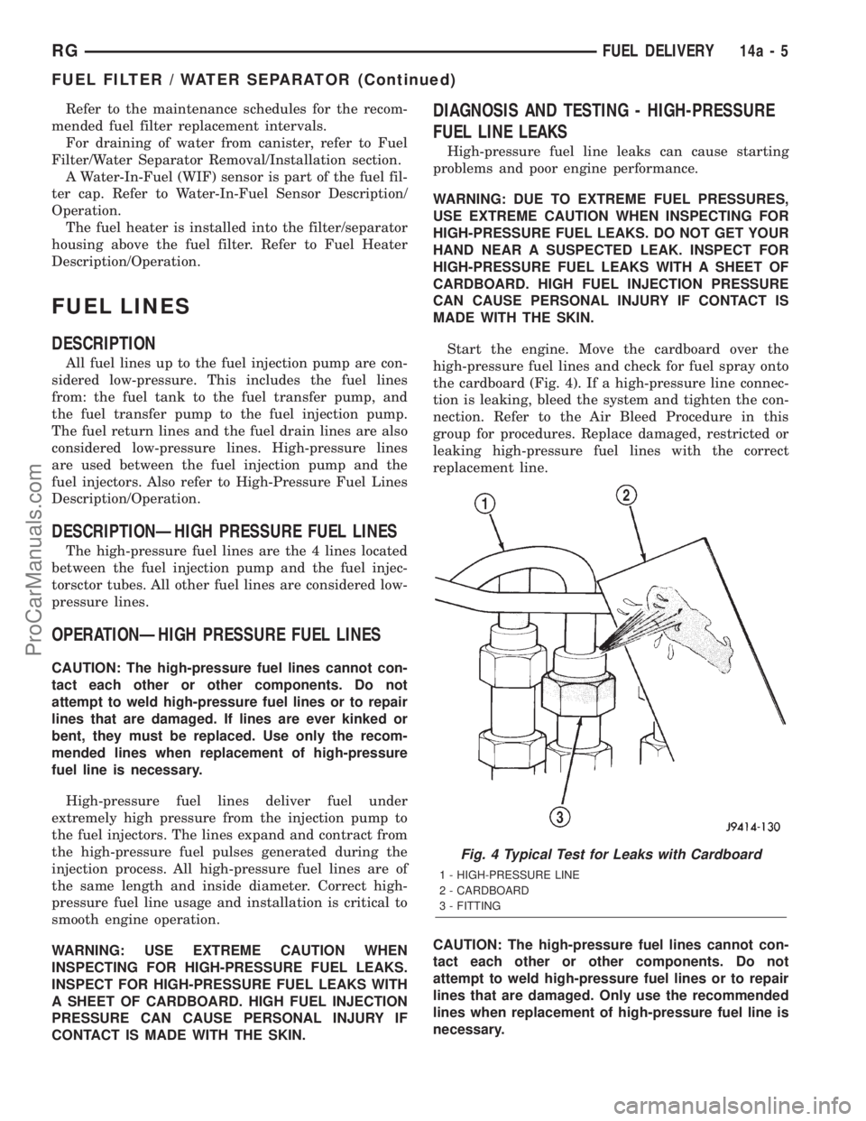
Start the engine. Move the cardboard over the
high-pressure fuel lines and check for fuel spray onto
the cardboard (Fig. 4). If a high-pressure line connec-
tion is leaking, bleed the system and tighten the con-
nection. Refer to the Air Bleed Procedure in this
group for procedures. Replace damaged, restricted or
leaking high-pressure fuel lines with the correct
replacement line.
CAUTION: The high-pressure fuel lines cannot con-
tact each other or other components. Do not
attempt to weld high-pressure fuel lines or to repair
lines that are damaged. Only use the recommended
lines when replacement of high-pressure fuel line is
necessary.
Fig. 4 Typical Test for Leaks with Cardboard
1 - HIGH-PRESSURE LINE
2 - CARDBOARD
3 - FITTING
RGFUEL DELIVERY14a-5
FUEL FILTER / WATER SEPARATOR (Continued)
ProCarManuals.com
Page 1450 of 2321
(12) Install accessory drive belt (Refer to 7 -
COOLING/ACCESSORY DRIVE/DRIVE BELTS -
INSTALLATION).
(13) Install power steering belt (Refer to 7 -
COOLING/ACCESSORY DRIVE/DRIVE BELTS -
INSTALLATION).
(14) Install air cleaner housing assembly.
(15) Install engine cover (Refer to 9 - ENGINE -
INSTALLATION).
(16) Connect negative battery cable.
WATER IN FUEL SENSOR
DESCRIPTION
The WIF sensor is located in the bowl assembly of
the fuel filter/water separator.
OPERATION
The sensor sends an input to the Engine Control
Module (ECM) when it senses water in the fuel filter/
water separator. As the water level in the filter/sep-
arator increases, the resistance across the WIF
sensor decreases. This decrease in resistance is sent
as a signal to the ECM and compared to a high
water standard value. Once the value reaches 30 to
40 kilohms, the ECM will activate the water-in-fuel
warning lamp through CCD bus circuits. This all
takes place when the ignition key is initially put in
the ON position. The ECM continues to monitor the
input at the end of the intake manifold air heater
post-heat cycle.
RGFUEL DELIVERY14a-9
FUEL INJECTION PUMP (Continued)
ProCarManuals.com
Page 1467 of 2321
COLUMN
TABLE OF CONTENTS
page page
COLUMN
DESCRIPTION...........................10
WARNING..............................10
DIAGNOSIS AND TESTING.................12
STEERING COLUMN....................12
REMOVAL..............................12
INSTALLATION...........................13
SPECIFICATIONS........................14
KEY/LOCK CYLINDER
DESCRIPTION...........................14OPERATION.............................14
REMOVAL..............................14
INSTALLATION...........................14
GEAR SHIFT LEVER
REMOVAL..............................15
INSTALLATION...........................15
SHROUD
REMOVAL..............................16
INSTALLATION...........................16
COLUMN
DESCRIPTION - STEERING COLUMN
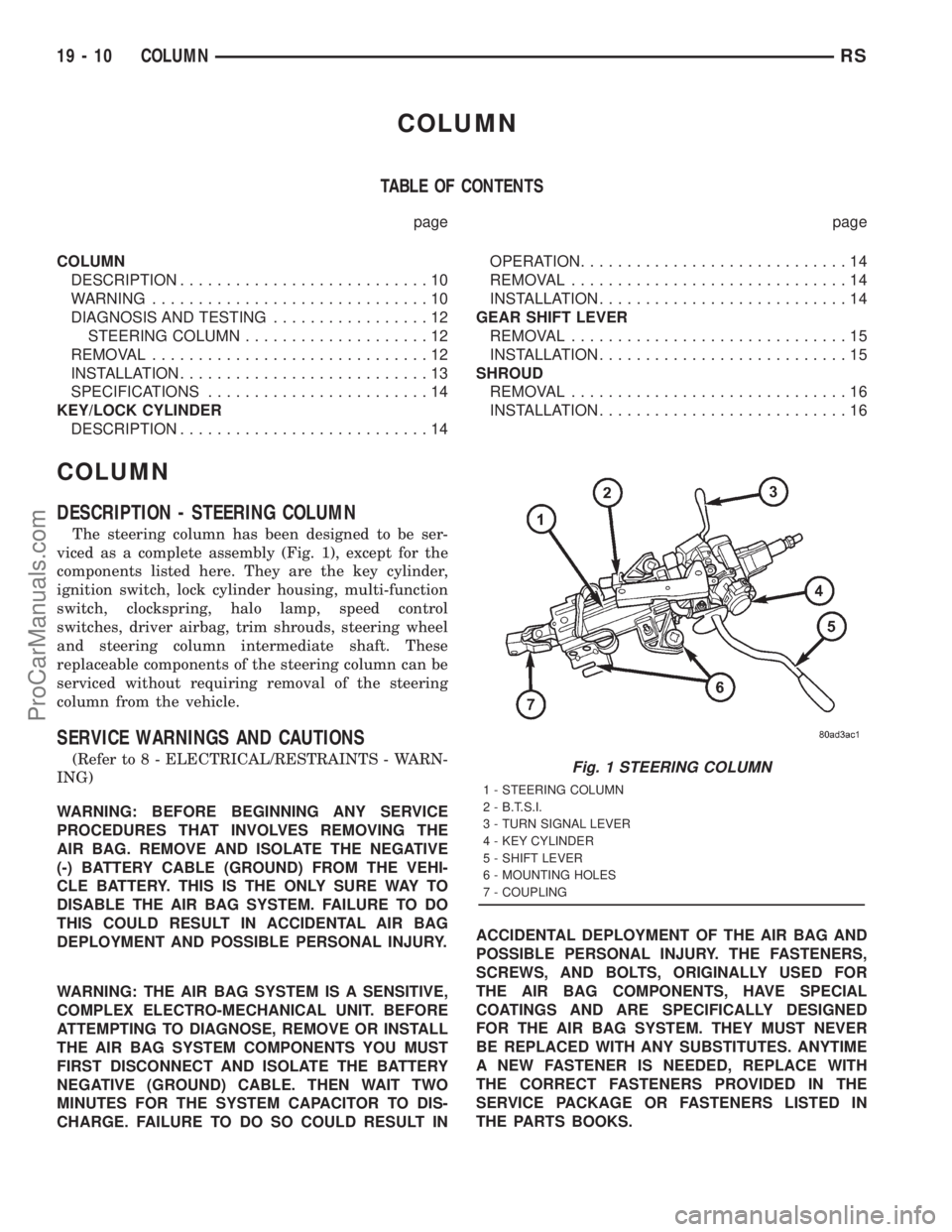
The steering column has been designed to be ser-
viced as a complete assembly (Fig. 1), except for the
components listed here. They are the key cylinder,
ignition switch, lock cylinder housing, multi-function
switch, clockspring, halo lamp, speed control
switches, driver airbag, trim shrouds, steering wheel
and steering column intermediate shaft. These
replaceable components of the steering column can be
serviced without requiring removal of the steering
column from the vehicle.
SERVICE WARNINGS AND CAUTIONS
(Refer to 8 - ELECTRICAL/RESTRAINTS - WARN-
ING)
WARNING: BEFORE BEGINNING ANY SERVICE
PROCEDURES THAT INVOLVES REMOVING THE
AIR BAG. REMOVE AND ISOLATE THE NEGATIVE
(-) BATTERY CABLE (GROUND) FROM THE VEHI-
CLE BATTERY. THIS IS THE ONLY SURE WAY TO
DISABLE THE AIR BAG SYSTEM. FAILURE TO DO
THIS COULD RESULT IN ACCIDENTAL AIR BAG
DEPLOYMENT AND POSSIBLE PERSONAL INJURY.
WARNING: THE AIR BAG SYSTEM IS A SENSITIVE,
COMPLEX ELECTRO-MECHANICAL UNIT. BEFORE
ATTEMPTING TO DIAGNOSE, REMOVE OR INSTALL
THE AIR BAG SYSTEM COMPONENTS YOU MUST
FIRST DISCONNECT AND ISOLATE THE BATTERY
NEGATIVE (GROUND) CABLE. THEN WAIT TWO
MINUTES FOR THE SYSTEM CAPACITOR TO DIS-
CHARGE. FAILURE TO DO SO COULD RESULT INACCIDENTAL DEPLOYMENT OF THE AIR BAG AND
POSSIBLE PERSONAL INJURY. THE FASTENERS,
SCREWS, AND BOLTS, ORIGINALLY USED FOR
THE AIR BAG COMPONENTS, HAVE SPECIAL
COATINGS AND ARE SPECIFICALLY DESIGNED
FOR THE AIR BAG SYSTEM. THEY MUST NEVER
BE REPLACED WITH ANY SUBSTITUTES. ANYTIME
A NEW FASTENER IS NEEDED, REPLACE WITH
THE CORRECT FASTENERS PROVIDED IN THE
SERVICE PACKAGE OR FASTENERS LISTED IN
THE PARTS BOOKS.Fig. 1 STEERING COLUMN
1 - STEERING COLUMN
2 - B.T.S.I.
3 - TURN SIGNAL LEVER
4 - KEY CYLINDER
5 - SHIFT LEVER
6 - MOUNTING HOLES
7 - COUPLING
19 - 10 COLUMNRS
ProCarManuals.com